EP1507158B1 - Schutzhülle für optische Geräte - Google Patents
Schutzhülle für optische Geräte Download PDFInfo
- Publication number
- EP1507158B1 EP1507158B1 EP04018137.2A EP04018137A EP1507158B1 EP 1507158 B1 EP1507158 B1 EP 1507158B1 EP 04018137 A EP04018137 A EP 04018137A EP 1507158 B1 EP1507158 B1 EP 1507158B1
- Authority
- EP
- European Patent Office
- Prior art keywords
- protective case
- case according
- protective
- protective cover
- optical device
- Prior art date
- Legal status (The legal status is an assumption and is not a legal conclusion. Google has not performed a legal analysis and makes no representation as to the accuracy of the status listed.)
- Expired - Lifetime
Links
- 230000001681 protective effect Effects 0.000 title claims description 110
- 230000003287 optical effect Effects 0.000 title claims description 27
- 239000004033 plastic Substances 0.000 claims description 28
- 229920003023 plastic Polymers 0.000 claims description 28
- 239000004753 textile Substances 0.000 claims description 23
- 239000000463 material Substances 0.000 claims description 19
- 239000005038 ethylene vinyl acetate Substances 0.000 claims description 4
- DQXBYHZEEUGOBF-UHFFFAOYSA-N but-3-enoic acid;ethene Chemical compound C=C.OC(=O)CC=C DQXBYHZEEUGOBF-UHFFFAOYSA-N 0.000 claims description 3
- 230000004297 night vision Effects 0.000 claims description 3
- 229920001200 poly(ethylene-vinyl acetate) Polymers 0.000 claims description 3
- 239000011521 glass Substances 0.000 claims 1
- 230000035939 shock Effects 0.000 description 6
- 230000007613 environmental effect Effects 0.000 description 5
- 238000000034 method Methods 0.000 description 5
- 238000000465 moulding Methods 0.000 description 5
- 239000004744 fabric Substances 0.000 description 4
- 238000004519 manufacturing process Methods 0.000 description 3
- 230000008569 process Effects 0.000 description 3
- 238000006748 scratching Methods 0.000 description 2
- 230000002393 scratching effect Effects 0.000 description 2
- 239000000725 suspension Substances 0.000 description 2
- XLYOFNOQVPJJNP-UHFFFAOYSA-N water Substances O XLYOFNOQVPJJNP-UHFFFAOYSA-N 0.000 description 2
- 239000004952 Polyamide Substances 0.000 description 1
- 230000009471 action Effects 0.000 description 1
- 230000008859 change Effects 0.000 description 1
- 238000005253 cladding Methods 0.000 description 1
- 239000011248 coating agent Substances 0.000 description 1
- 238000000576 coating method Methods 0.000 description 1
- 238000010276 construction Methods 0.000 description 1
- 230000001419 dependent effect Effects 0.000 description 1
- 230000000694 effects Effects 0.000 description 1
- 229920001971 elastomer Polymers 0.000 description 1
- 239000006260 foam Substances 0.000 description 1
- 230000006870 function Effects 0.000 description 1
- 238000007731 hot pressing Methods 0.000 description 1
- 239000010985 leather Substances 0.000 description 1
- 229920002647 polyamide Polymers 0.000 description 1
- 229920000728 polyester Polymers 0.000 description 1
- 229920006149 polyester-amide block copolymer Polymers 0.000 description 1
- 238000003825 pressing Methods 0.000 description 1
- 230000009993 protective function Effects 0.000 description 1
- 230000009467 reduction Effects 0.000 description 1
- 239000005060 rubber Substances 0.000 description 1
- 239000004576 sand Substances 0.000 description 1
- 238000007493 shaping process Methods 0.000 description 1
- 239000000126 substance Substances 0.000 description 1
- 229920001169 thermoplastic Polymers 0.000 description 1
- 239000004416 thermosoftening plastic Substances 0.000 description 1
Images

Classifications
-
- A—HUMAN NECESSITIES
- A45—HAND OR TRAVELLING ARTICLES
- A45C—PURSES; LUGGAGE; HAND CARRIED BAGS
- A45C5/00—Rigid or semi-rigid luggage
- A45C5/02—Materials therefor
-
- A—HUMAN NECESSITIES
- A45—HAND OR TRAVELLING ARTICLES
- A45C—PURSES; LUGGAGE; HAND CARRIED BAGS
- A45C11/00—Receptacles for purposes not provided for in groups A45C1/00-A45C9/00
- A45C11/08—Cases for telescopes or binoculars
Definitions
- the present invention relates to a protective cover for optical devices, namely telescopes, telescopes, night vision devices or binoculars.
- optical devices are often used in different locations and therefore need to be transported. It is important that the optical devices are effectively protected from damage by external influences such as shocks, shocks, moisture or scratching.
- the protective cover may be exposed to environmental influences such as rain, sand or sunlight for long periods of time.
- covers for optical devices should also have the lowest possible weight to increase the ease of use, and should allow a quick and quiet removal or attachment of the shell. The latter aspect is particularly important in wildlife observations in the wild.
- a cost-effective production of the shell requires that the materials used can be processed easily and without great effort.
- Protective covers for observation telescopes which have a tubular shape and consist of textile materials or leather.
- these conventional materials often have the disadvantage that they are either difficult and thus expensive to process or allow weight savings only at the expense of mechanical stability and resistance to environmental influences.
- sheaths are often of a nature that does not allow for full utilization of the device within the sheath, especially because it is not all functional parts of the optical device in the case are accessible from the outside.
- the complete removal of the protective cover can be associated with a considerable amount of time and cause disturbing noises, which are undesirable in particular in animal observations.
- protective covers for telescopes which have at their ends covers for eyepieces and lenses. Again, the nature of these covers often means that they can not be removed silently from their original position or that they interfere after their removal from the protective starting position in the use of the optical device, for example because they are attached to the sleeve via straps and hang down loosely after removing.
- a protective cover for riflescopes is known, which consists of sewn together with textile material coated rubber parts.
- the present invention is therefore an object of the invention to provide a protective cover for optical devices, which offers the best possible protection against external influences such as shocks, shocks, scratching but also environmental influences such as moisture and sunlight and thereby has the lowest possible weight. Furthermore, an object of the present invention is to be seen to make the protective cover so that a quick and quiet use of all possible functions of the optical device is possible. In addition, the present invention has made it to the task of providing the protective cover of a material that can be easily processed to any shape in larger quantities.
- Thermoformable plastics are plastics that can be converted to a softened state by the action of heat and then preformed into a desired structure by suitable molding techniques. Suitable plastics are thermoplastics.
- the thermoformable plastic comprises ethylene-vinyl acetate (EVA).
- EVA ethylene-vinyl acetate
- the plastic comprises ethylene-vinyl acetate foam, laminated with bi-elastic substances.
- the inventive thermoformable plastic (2) has a low weight and has a good shock and shock absorbing effect.
- thermoformable plastic can first be provided as a flat plastic surface, from which a suitable shape is punched out, which is then thermoformed.
- the molding of the thermoformable plastic may take place using current molding techniques, e.g. by hot pressing.
- the molding processes are carried out at temperatures which are sufficiently high to convert the plastic used to a softened state.
- shaping takes place at a temperature in the range of 100 ° C to 250 ° C, preferably 150 ° C to 200 ° C.
- thermoformable plastic which is preformed so that it at least partially envelops an optical device contained in the shell, is easy to work with and allows the production of any structures. Thereby, the shape of the protective cover can be optimally adapted to that of the optical device.
- the thermoformable plastic is preformed so that it fits tightly at least at a portion of the optical device. This causes an optimal fixation of the optical device within the protective cover, whereby a disturbing slipping and a consequent change of already made device settings during transport is avoided.
- the inventive protective cover can be adapted to telescopes, telescopes, night vision devices or binoculars due to the thermoformable plastic.
- the thermoformable plastic is at least partially coated with an elastic textile material.
- an elastic textile material By coating with a textile material, the protective effect of the shell against environmental influences is increased.
- the elasticity of the textile material furthermore ensures that the deformation forces acting on the protective cover can be better adapted and mechanical loads are more resistant.
- the textile material may be formed both as a textile fabric as well as knitted fabric. Preference is given to bi-elastic tissues. Suitable textile materials may include polyester and / or polyamide. If the textile material is exposed to a higher temperature during the production process over a certain period of time, polyester is preferred.
- thermoformable plastic can be preformed to any structures taking into account the optical device to be included.
- the protective cover is substantially cylindrical and has at least one open end, preferably two open ends. Due to the open ends, e.g. a cylindrical optical device with lens and eyepiece can also be used without removing the protective cover.
- thermoformable plastic can completely encase the optical device when the protective function of the cladding is in the foreground and the optical device is to be completely removed for its use of the protective cover.
- the protective cover has band-stitched suspension loops, in which a strap can be hung.
- three suspension loops are attached to the outside of the shell.
- protective caps can be attached to open ends of the protective cover. These ensure e.g. a protection of the lens and / or eyepiece of the optical device.
- the protective caps are detachably connected to the protective cover, so that they can be completely removed if necessary.
- an opening tab may be attached to the protective cap, which is then removed by simply pulling on a tab quickly and quietly.
- the protective caps may also comprise a thermoformable preformed plastic.
- the plastic is at least partially coated with an elastic textile material.
- the same thermoformable plastic and elastic fabric are used for the protective cover and the protective cap (s).
- the protective caps may have a zipper.
- the zipper extends continuously over a longitudinal side of the protective cap, the closed end of the protective cap and the opposite longitudinal side, so that the cap can be opened or closed on this entire length by pressing the zipper.
- Both the edges of the protective cover and the protective caps can be banded sewn, whereby the durability is increased.
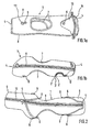
- Figure 1a respectively.
- Figure 1b shows a cylindrically shaped at least in some areas protective cover (1) without protective caps (5).
- the protective cover is substantially cylindrical.
- the protective caps (5) can be attached later via push buttons (6) on the protective cover.
- the protective cover (1) is made of a thermoformable plastic (2), which is preformed in a molding process is that it can adapt as closely as possible to the structure of the optical device to be recorded.
- the plastic (2) is coated on both sides with an elastic textile material (3).
- the three-layer construction is in Fig. 1b indicated schematically.
- This textile material (3) can extend over the entire plastic surface.
- the textile material (3) comprises a bi-elastic textile fabric which, due to its high elasticity present in at least two spatial directions, can also adapt to strongly deformed and curved surfaces.
- the protective cover (1) can have at least one zipper (8), which is preferably attached along the cylinder wall in the longitudinal direction.
- the protective cover can have at least one further opening (13) which can serve to drain any incoming water or condensed water again.
- a textile band (14) may be attached, which is formed at its ends to loops.
- a partial region (15) of at least one outer end of the protective covering (1) can be lowered slightly in relation to the surrounding protective covering surface. Through this lowered surface area, a later-mounted protective cap (5) nestles better on the protective cover (1). By the extent of the reduction can be controlled to what extent the protective cap (5) is embedded in the protective sleeve surface.
- Fig. 2 shows a protective cover (1) which is substantially cylindrical and at the open ends (4) protective caps (5) are mounted.
- the protective caps have an open end and an opposite closed end and are suitable for example for receiving a lens or eyepiece of an optical device.
- Both protective caps (5) are connected via push buttons (6) releasably connected to the protective cover (1).
- the protective caps (5) can have tabs (9). By simply pulling on a tab (9), a protective cap (5) can be easily removed.
- the longitudinal axes of protective cover (1) and protective caps (5) are substantially parallel.
- the longitudinal axis of the protective sheath (1) is defined as extending from one open end (4) to the opposite open end (4).
- the longitudinal axes of the protective caps extend from one open end to the opposite closed end.
- Fig. 3 shows the protective cover (1) with protective caps (5) in a linear arrangement, wherein one of the protective caps (5) has been pivoted out of its initial position by about 90 °, so that a originally covered by this cap end (4) is exposed again.
- the protective cover (1) can have at least one open end (4) which is provided with a protective cap (5) which is pivotable within a plane.
- a protective cap (5) which is pivotable within a plane.
- all attached protective caps (5) are pivotable within a plane. If a protective cap (5) is connected to the protective cover (1) via two pushbuttons (6), the rotation of the cap (5) can take place about the connecting axis of the two pushbuttons (6). This pivoting of the protective caps (5) makes it possible, for example, to expose the lens and eyepiece quickly and quietly as soon as an observation object is discovered.
- Fig. 4 shows a protective cover (1) with two protective caps (5), wherein the longitudinal axis of the protective cover (1) and the longitudinal axis of a protective cap (5) in an angled arrangement to each other.
- the longitudinal axes may include an angle of 35 ° to 55 °, preferably 40 ° to 50 °.
- This embodiment allows, for example, the inclusion of a telescope or observation telescope whose eyepiece is mounted in an angled arrangement on the optical device.
Landscapes
- Chemical & Material Sciences (AREA)
- Engineering & Computer Science (AREA)
- Materials Engineering (AREA)
- Telescopes (AREA)
Description
- Die vorliegende Erfindung betrifft eine Schutzhülle für optische Geräte, nämlich Teleskope, Fernrohre, Nachtsichtgeräte oder Ferngläser.
- Diese Geräte werden häufig an verschiedenen Orten verwendet und müssen daher transportiert werden. Dabei ist wichtig, dass die optischen Geräte wirksam vor Beschädigungen durch äussere Einflüsse wie Stösse, Erschütterungen, Feuchtigkeit oder Verkratzen geschützt werden. Insbesondere bei der Verwendung von Teleskopen für Naturbeobachtungen ist zu beachten, dass die Schutzhülle über längere Zeiträume Umwelteinflüssen wie Regen, Sand oder Sonneneinstrahlung ausgesetzt sein kann. Ausser einer hohen Widerstandsfähigkeit gegenüber äusseren Umwelteinflüssen sollten derartige Schutzhüllen für optische Geräte auch ein möglichst geringes Gewicht aufweisen, um den Verwendungskomfort zu erhöhen, und sollten ein schnelles sowie geräuscharmes Entfernen bzw. Anbringen der Hülle ermöglichen. Letzterer Gesichtspunkt ist insbesondere bei Tierbeobachtungen in freier Natur von Bedeutung. Weiterhin setzt eine kostengünstige Herstellungsweise der Hülle voraus, dass sich die verwendeten Materialien problemlos und ohne grossen Aufwand verarbeiten lassen.
- Es sind Schutzhüllen für Beobachtungsfernrohre bekannt, die eine schlauchartige Form aufweisen und aus Textilstoffen oder Leder bestehen. Diese herkömmlichen Materialien haben jedoch häufig den Nachteil, dass sie entweder schwierig und damit kostenintensiv zu verarbeiten sind oder eine Gewichtsersparnis nur auf Kosten der mechanischen Stabilität und der Widerstandskraft gegen Umwelteinflüsse ermöglichen. Auch sind derartige Hüllen häufig von einer Beschaffenheit, die eine vollständige Nutzung des Geräts innerhalb der Hülle nicht ermöglicht, insbesondere weil nicht sämtliche Funktionsteile des optischen Geräts in der Hülle von aussen zugänglich sind. Die vollständige Entfernung der Schutzhülle kann jedoch mit einem erheblichen Zeitaufwand verbunden sein und störende Geräusche verursachen, die insbesondere bei Tierbeobachtungen unerwünscht sind.
- Weiterhin sind Schutzhüllen für Fernrohre bekannt, die an ihren Enden Abdeckungen für Okulare und Objektive aufweisen. Auch hier führt die Beschaffenheit dieser Abdeckungen häufig dazu, dass diese sich nicht geräuscharm aus ihrer ursprünglichen Position entfernen lassen oder dass sie nach ihrer Entfernung aus der schützenden Ausgangsposition bei der Verwendung des optischen Geräts stören, z.B. weil sie über Gurte an der Hülle befestigt sind und nach dem Abnehmen lose herunterhängen.
AusUS-A-5183953 ist eine Schutzhülle für Zielfernrohre bekannt, die aus zusammengenähten, mit Textilmaterial beschichteten Gummiteilen besteht. - Der vorliegenden Erfindung liegt daher die Aufgabe zugrunde, eine Schutzhülle für optische Geräte bereitzustellen, die einen möglichst guten Schutz gegenüber äusseren Einwirkungen wie Stössen, Erschütterungen, Verkratzen aber auch Umwelteinflüssen wie Feuchtigkeit und Sonneneinstrahlung bietet und dabei ein möglichst geringes Gewicht aufweist. Weiterhin ist eine Aufgabe der vorliegenden Erfindung darin zu sehen, die Schutzhülle so zu gestalten, dass eine schnelle und geräuscharme Verwendung möglichst aller Funktionen des optischen Geräts möglich ist. Darüber hinaus hat es sich die vorliegende Erfindung zur Aufgabe gemacht, die Schutzhülle aus einem Material bereitzustellen, das auch in grösseren Mengen problemlos zu beliebigen Formen verarbeitet werden kann.
- Diese Aufgaben werden erfindungsgemäß durch die Schutzhülle nach Anspruch 1 gelöst.
Bei thermoformbaren Kunststoffen handelt es sich um Kunststoffe, die sich unter Einwirkung von Wärme in einen erweichten Zustand überführen lassen, um dann durch geeignete Formgebungsverfahren zu einer gewünschten Struktur vorgeformt zu werden. Geeignete Kunststoffe sind Thermoplaste. In einer bevorzugten Ausführungsform umfasst der thermoformbare Kunststoff Ethylen-Vinylacetat (EVA). Besonders bevorzugt umfasst der Kunststoff Ethylen-Vinylacetat-Schaum, kaschiert mit bielastischen Stoffen. Der erfindungsgemässe thermoformbare Kunststoff (2) weist ein geringes Gewicht auf und hat eine gute Stoss- und Schock absorbierende Wirkung. - Der thermoformbare Kunststoff kann zunächst als ebene Kunststofffläche bereitgestellt werden, aus der eine passende Form ausgestanzt wird, die dann warm verformt wird. Die Formgebung des thermoformbaren Kunststoffs kann unter Verwendung gängiger Formgebungsverfahren stattfinden, z.B. durch Heisspressen.
- Die Formgebungsverfahren werden bei Temperaturen durchgeführt, die ausreichend hoch sind, um den verwendeten Kunststoff in einen erweichten Zustand zu überführen. Bei der Verwendung von Ethylen-Vinylacetat findet die Formgebung bei einer Temperatur im Bereich von 100°C bis 250°C, bevorzugt 150°C bis 200°C statt.
- Der erfindungsgemässe thermoformbare Kunststoff, der so vorgeformt ist, dass er ein in der Hülle enthaltenes optisches Gerät zumindest teilweise umhüllt, ist gut zu verarbeiten und ermöglicht die Herstellung beliebiger Strukturen. Dadurch kann die Form der Schutzhülle optimal an diejenige des optischen Geräts angepasst werden. In einer bevorzugten Ausführungsform ist der thermoformbare Kunststoff so vorgeformt, dass er zumindest an einem Teilbereich des optischen Geräts eng anliegt. Dies bewirkt eine optimale Fixierung des optischen Geräts innerhalb der Schutzhülle, wodurch ein störendes Verrutschen und eine dadurch bedingte Veränderung von bereits vorgenommenen Geräteeinstellungen beim Transport vermieden wird.
- Die erfindungsgemässe Schutzhülle kann aufgrund des thermoformbaren Kunststoffes an Teleskope, Fernrohre, Nachtsichtgeräte oder Ferngläser angepasst werden.
- Gemäss einer bevorzugten Ausführungsform ist der thermoformbare Kunststoff zumindest teilweise mit einem elastischen Textilmaterial beschichtet. Durch die Beschichtung mit einem Textilmaterial wird die Schutzwirkung der Hülle gegenüber Umwelteinflüssen erhöht. Die Elastizität des Textilmaterials bewirkt weiterhin, dass sich die Schutzhülle einwirkenden Verformungskräften besser anpassen kann und mechanischen Belastungen gegenüber widerstandsfähiger ist. Das Textilmaterial kann sowohl als Textilgewebe wie auch als Gewirke ausgebildet sein. Bevorzugt sind bielastische Gewebe. Geeignete Textilmaterialien können Polyester und/oder Polyamid umfassen. Wird das Textilmaterial beim Herstellungsverfahren über einen gewissen Zeitraum einer höheren Temperatur ausgesetzt, ist Polyester bevorzugt.
- Der thermoformbare Kunststoff kann unter Berücksichtigung des aufzunehmenden optischen Geräts zu beliebigen Strukturen vorgeformt werden. In einer bevorzugten Ausführungsform ist die Schutzhülle im Wesentlichen zylinderförmig und weist zumindest ein offenes Ende , bevorzugt zwei offene Enden auf. Aufgrund der offenen Enden kann z.B. ein zylinderförmiges optisches Gerät mit Objektiv und Okular auch ohne Entfernung der Schutzhülle verwendet werden.
- Alternativ kann der thermoformbare Kunststoff das optische Gerät vollständig umhüllen, wenn die Schutzfunktion der Hülle im Vordergrund steht und das optische Gerät für seine Verwendung der Schutzhülle vollständig entnommen werden soll.
- In einer bevorzugten Ausführungsform weist die Schutzhülle bandvernähte Aufhängungsschleifen auf, in die ein Trageriemen eingehängt werden kann. Bevorzugt werden drei Aufhängungsschleifen an der Hüllenaussenseite angebracht.
- Gemäss einer bevorzugten Ausführungsform können an offenen Enden der Schutzhülle Schutzkappen angebracht werden. Diese gewährleisten z.B. einen Schutz von Objektiv und/oder Okular des optischen Geräts. Bevorzugt sind die Schutzkappen lösbar mit der Schutzhülle verbunden, so dass sie bei Bedarf auch vollständig entfernt werden können. Hierzu kann eine Öffnungslasche an der Schutzkappe angebracht sein, die dann durch einfaches Ziehen an einer Lasche schnell und geräuscharm entfernt wird.
- Gemäss der Erfindung können die Schutzkappen ebenfalls einen thermoformbaren, vorgeformten Kunststoff umfassen. Bevorzugt ist der Kunststoff zumindest teilweise mit einem elastischen Textilmaterial beschichtet. In einer bevorzugten Ausführungsform werden für die Schutzhülle und die Schutzkappe(n) derselbe thermoformbare Kunststoff und dasselbe elastische Textilmaterial verwendet.
- Erfindungsgemäss können die Schutzkappen einen Reissverschluss aufweisen. Bevorzugt verläuft der Reissverschluss durchgehend über eine Längsseite der Schutzkappe, das geschlossene Ende der Schutzkappe sowie die gegenüberliegende Längsseite, so dass die Kappe auf dieser gesamten Länge durch Betätigung des Reissverschlusses geöffnet oder geschlossen werden kann.
- Sowohl die Ränder der Schutzhülle als auch der Schutzkappen können bandeingenäht sein, wodurch die Haltbarkeit erhöht wird.
- Weitere bevorzugte Ausführungsformen werden in den abhängigen Ansprüchen offenbart.
- Zum besseren Verständnis werden im folgenden erfindungsgemässe Ausführungsformen anhand der beigefügten Abbildungen eingehender erläutert.
-
-
Abb. 1a die Schutzhülle (1) ohne Schutzkappen (5); -
Abb. 1b die Schutzhülle (1) gemässAbb. 1a , jedoch um 90°gedreht; -
Abb. 2 die Schutzhülle (1) in linearer Anordnung mit den Schutzkappen (5); -
Abb. 3 die Schutzhülle (1) gemässAbb. 2 , wobei jedoch eine Schutzkappe (5) um 90°geschwenkt wurde; und -
Abb. 4 die Schutzhülle (1) in gewinkelter Anordnung mit einer Schutzkappe (5). -
Abbildung 1a bzw.Abbildung 1b zeigt eine zumindest in Teilbereichen zylinderförmig ausgestaltete Schutzhülle (1) ohne Schutzkappen (5). Bevorzugt ist die Schutzhülle im Wesentlichen zylinderförmig. Die Schutzkappen (5) können später über Druckknöpfe (6) an der Schutzhülle befestigt werden. Die Schutzhülle (1) ist aus einem thermoformbaren Kunststoff (2) gefertigt, der in einem Formgebungsverfahren so vorgeformt wird, dass er sich der Struktur des aufzunehmenden optischen Geräts möglichst enganliegend anpassen kann. Der Kunststoff (2) ist beidseitig mit einem elastischen Textilmaterial (3) beschichtet. Der dreischichtige Aufbau ist inAbb. 1b schematisch angedeutet. Dieses Textilmaterial (3) kann sich über die gesamte Kunststoffoberfläche erstrecken. Bevorzugt umfasst das Textilmaterial (3) ein bielastisches Textilgewebe, das sich aufgrund seiner zumindest in zwei Raumrichtungen vorhandenen hohen Elastizität auch stark verformten und gekrümmten Oberflächen anpassen kann. - Neben den Öffnungen (4) am Ende der Schutzhülle (1) kann diese noch weitere Öffnungen (7) aufweisen, die bevorzugt so angebracht sind, dass eine Oberfläche des optischen Geräts zugänglich ist, die der Schärfeneinstellung, Vergrößerung oder der Anbringung eines Stativs dient. Dies gewährleistet eine umfassende Nutzung des Geräts, ohne dass eine Abnahme der Schutzhülle (1) notwendig ist.
- Weiterhin kann die Schutzhülle (1) zumindest einen Reißverschluss (8) aufweisen, der bevorzugt entlang der Zylinderwand in Längsrichtung angebracht ist. In einer bevorzugten Ausführungsform liegen zwei Reißverschlüsse (8) vor, die auf gegenüberliegenden Seiten der zylinderförmigen Hülle angebracht sind und sich entlang der gesamten Längsrichtung der Zylinderwand erstrecken.
- Gemäß einer weiteren bevorzugten Ausführungsform kann die Schutzhülle zumindest eine weitere Öffnung (13) aufweisen, die dazu dienen kann, eventuell einlaufendes Wasser oder Kondenswasser wieder ablaufen zu lassen. Weiterhin kann auf der Oberseite der Schutzhülle (1) ein Textilband (14) angebracht sein, das an seinen Enden zu Schlaufen ausgebildet ist.
- Erfindungsgemäß kann ein Teilbereich (15) zumindest eines äußeren Endes der Schutzhülle (1) gegenüber der umgebenden Schutzhüllenoberfläche etwas abgesenkt sein. Durch diesen tiefer gelegten Oberflächenbereich schmiegt sich eine später angebrachte Schutzkappe (5) besser an die Schutzhülle (1). Durch das Ausmaß der Absenkung kann gesteuert werden, in welchem Maße die Schutzkappe (5) in die Schutzhüllenoberfläche eingebettet wird.
-
Abb. 2 zeigt eine Schutzhülle (1), die im Wesentlichen zylinderförmig ist und an deren offenen Enden (4) Schutzkappen (5) angebracht sind. Die Schutzkappen weisen ein offenes Ende sowie ein gegenüberliegendes geschlossenes Ende auf und eignen sich beispielsweise zur Aufnahme eines Objektivs oder Okulars eines optischen Geräts. Beide Schutzkappen (5) sind über Druckknöpfe (6) lösbar mit der Schutzhülle (1) verbunden. Weiterhin können die Schutzkappen (5) Laschen (9) aufweisen. Durch einfaches Ziehen an einer Lasche (9) kann eine Schutzkappe (5) problemlos entfernt werden. - Weiterhin verlaufen die Längsachsen von Schutzhülle (1) und Schutzkappen (5) im Wesentlichen parallel. Gemäß der Erfindung wird die Längsachse der Schutzhülle (1) so definiert, dass sie von einem offenen Ende (4) zum gegenüberliegenden offenen Ende (4) verläuft. Die Längsachsen der Schutzkappen verlaufen von einem offenen Ende zum gegenüberliegenden geschlossenen Ende. Durch diese im Wesentlichen lineare Anordnung von Schutzkappen (5) und Schutzhülle (1) eignet sich diese Vorrichtung z.B. zur Aufnahme eines Beobachtungsfernrohrs, dessen Okular ebenfalls in einer linearen bzw. geraden Anordnung am optischen Gerät befestigt ist.
-
Abb. 3 zeigt die Schutzhülle (1) mit Schutzkappen (5) in linearer Anordnung, wobei eine der Schutzkappen (5) aus ihrer Ausgangsposition heraus um etwa 90° geschwenkt wurde, so dass ein ursprünglich durch diese Schutzkappe verdecktes Ende (4) wieder freigelegt wird. - Erfindungsgemäß kann die Schutzhülle (1) zumindest ein offenes Ende (4) aufweisen, das mit einer Schutzkappe (5) versehen ist, die innerhalb einer Ebene schwenkbar ist. Bevorzugt sind alle angebrachten Schutzkappen (5) innerhalb einer Ebene schwenkbar. Wird eine Schutzkappe (5) über zwei Druckknöpfe (6) mit der Schutzhülle (1) verbunden, so kann die Drehung der Kappe (5) um die Verbindungsachse der beiden Druckknöpfe (6) erfolgen. Diese Schwenkbarkeit der Schutzkappen (5) ermöglicht es beispielsweise, Objektiv und Okular schnell und geräuscharm freizulegen, sobald ein Beobachtungsobjekt entdeckt wird.
-
Abb. 4 zeigt eine Schutzhülle (1) mit zwei Schutzkappen (5), wobei die Längsachse der Schutzhülle (1) und die Längsachse einer Schutzkappe (5) in einer gewinkelten Anordnung zueinander vorliegen. Die Längsachsen können einen Winkel von 35° bis 55°, bevorzugt 40° bis 50° einschließen. Diese Ausführungsform ermöglicht z.B. die Aufnahme eines Teleskops oder Beobachtungsfernrohrs, dessen Okular in einer abgewinkelten Anordnung am optischen Gerät befestigt ist.
Claims (15)
- Schutzhülle zur Aufnahme optischer Geräte in Form von Teleskopen, Fernrohren, Nachtsichtgeräten oder Ferngläsern, wobei die Schutzhülle (1) einen thermoformbaren Kunststoff (2) umfasst, der teilweise mit einem elastischen Textilmaterial (3) beschichtet ist, und der so vorgeformt ist, dass er das optische Gerät zumindest teilweise umhüllt und dass er sich der Struktur des aufzunehmenden optischen Geräts möglichst eng anliegend anpassen kann.
- Schutzhülle nach Anspruch 1, dadurch gekennzeichnet, dass der thermoformbare Kunststoff (2) beidseitig mit dem elastischen Textilmaterial (3) beschichtet ist.
- Schutzhülle nach Anspruch 1 oder 2, dadurch gekennzeichnet, dass die Schutzhülle (1) im Wesentlichen zylinderförmig ist und zumindest ein offenes Ende (4) aufweist.
- Schutzhülle nach Anspruch 1 oder 2, dadurch gekennzeichnet, dass der thermoformbare Kunststoff (2) das optische Gerät vollständig umhüllt.
- Schutzhülle nach einem der Ansprüche 1-3, dadurch gekennzeichnet, dass die Schutzhülle (1) zumindest ein offenes Ende (4) aufweist, das mit einer Schutzkappe (5) versehen ist, wobei die Schutzkappe (5) innerhalb einer Ebene schwenkbar ist.
- Schutzhülle nach Anspruch 5, dadurch gekennzeichnet, dass die Schutzkappe (5) lösbar mit der Schutzhülle (1) verbunden ist.
- Schutzhülle nach Anspruch 6, dadurch gekennzeichnet, dass die Schutzkappe (5) über einen oder mehrere Druckknöpfe (6) an der Schutzhülle (1) angebracht ist.
- Schutzhülle nach einem der vorstehenden Ansprüche, dadurch gekennzeichnet, dass die Schutzkappe (5) einen thermoformbaren, vorgeformten Kunststoff umfasst, der gegebenenfalls zumindest teilweise mit einem elastischen Textilmaterial beschichtet ist.
- Schutzhülle nach einem der Ansprüche 5-8, dadurch gekennzeichnet, dass die Schutzhülle (1) zumindest zwei Schutzkappen (5) aufweist.
- Schutzhülle nach einem der vorstehenden Ansprüche, dadurch gekennzeichnet, dass der thermoformbare Kunststoff (2,) Ethylen-Vinylacetat-Kunststoff umfasst.
- Schutzhülle nach einem der vorstehenden Ansprüche, dadurch gekennzeichnet, dass das elastische Textilmaterial (3,) ein Textilgewebe und/oder ein Textilgewirke umfasst.
- Schutzhülle nach Anspruch 11, dadurch gekennzeichnet, dass das Textilgewebe ein bielastisches Textilgewebe umfasst.
- Schutzhülle nach einem der vorstehenden Ansprüche, dadurch gekennzeichnet, dass an der Schutzhülle (1) zumindest eine Öffnung (7) so angebracht ist, dass eine Oberfläche des optischen Gerätes zugänglich ist, die der Schärfeneinstellung, Vergrösserung oder der Anbringung eines Stativs dient.
- Schutzhülle nach einem der vorstehenden Ansprüche, dadurch gekennzeichnet, dass die Schutzhülle (1) zumindest einen Reissverschluss (8) und/oder einen Trageriemen (14) aufweist.
- Schutzhülle nach Anspruch 13, dadurch gekennzeichnet, dass die Längsachse der Schutzhülle (1) und die Längsachse zumindest einer Schutzkappe (5) im Wesentlichen parallel verlaufen oder einen Winkel von 35°C bis 55°C einschliessen.
Applications Claiming Priority (2)
| Application Number | Priority Date | Filing Date | Title |
|---|---|---|---|
| DE20312522U DE20312522U1 (de) | 2003-08-13 | 2003-08-13 | Schutzhülle für optische Geräte |
| DE20312522U | 2003-08-13 |
Publications (2)
| Publication Number | Publication Date |
|---|---|
| EP1507158A1 EP1507158A1 (de) | 2005-02-16 |
| EP1507158B1 true EP1507158B1 (de) | 2016-10-05 |
Family
ID=29265735
Family Applications (1)
| Application Number | Title | Priority Date | Filing Date |
|---|---|---|---|
| EP04018137.2A Expired - Lifetime EP1507158B1 (de) | 2003-08-13 | 2004-07-30 | Schutzhülle für optische Geräte |
Country Status (3)
| Country | Link |
|---|---|
| US (1) | US20050279659A1 (de) |
| EP (1) | EP1507158B1 (de) |
| DE (1) | DE20312522U1 (de) |
Families Citing this family (1)
| Publication number | Priority date | Publication date | Assignee | Title |
|---|---|---|---|---|
| US20180125190A1 (en) * | 2016-08-22 | 2018-05-10 | Darren Jones | Binoculars covers |
Citations (2)
| Publication number | Priority date | Publication date | Assignee | Title |
|---|---|---|---|---|
| US5183953A (en) * | 1992-01-08 | 1993-02-02 | Anderson Manufacturing Company, Inc. | Flexible cover/guard for rifle and piston scopes having a resilient protective inner portion and a fabric outer portion secured thereto |
| EP1300445A1 (de) * | 2001-03-02 | 2003-04-09 | Teijin Chemicals, Ltd. | Aromatische polycarbonatharzzusammensetzung |
Family Cites Families (13)
| Publication number | Priority date | Publication date | Assignee | Title |
|---|---|---|---|---|
| US3782614A (en) * | 1972-05-01 | 1974-01-01 | J Campisi | Binocular pocket |
| JPS5743419U (de) * | 1980-08-27 | 1982-03-10 | ||
| US4601318A (en) * | 1984-03-22 | 1986-07-22 | David Diegelman | Camera and lens case |
| US4704001A (en) * | 1985-08-26 | 1987-11-03 | Parandes Dana J | Novel lens carrier |
| US4703519A (en) * | 1986-01-06 | 1987-10-27 | Krenzel Ronald L | Sewn polyolefin and fabric bag and method of making bag |
| DE9016687U1 (de) * | 1990-12-10 | 1991-02-28 | Fa. Carl Zeiss, 7920 Heidenheim | Gehäuse zur Aufbewahrung von Ferngläsern |
| US5373980A (en) * | 1991-05-24 | 1994-12-20 | Pho | Lens case with selective circumferential compression |
| FR2686322B1 (fr) * | 1992-01-22 | 1994-04-29 | Conceptions Innov Indle Atel | Coussin gonflable pour emballage. |
| US5590777A (en) * | 1993-03-01 | 1997-01-07 | Ongard Systems, Inc. | Sterilizable flexible pouch package |
| US5529826A (en) * | 1994-02-15 | 1996-06-25 | Tailor; Dilip K. | Fabric-faced thermoplastic composite panel |
| US6095328A (en) * | 1999-01-14 | 2000-08-01 | The Brunton Company | Carrying case for binoculars |
| US6499584B1 (en) * | 1999-10-26 | 2002-12-31 | Merck & Co., Inc. | Method and apparatus for handling bulk bags |
| DE19953391A1 (de) * | 1999-11-06 | 2001-05-10 | Hensoldt & Soehne Optik | Gehäuse für ein Fernglas |
-
2003
- 2003-08-13 DE DE20312522U patent/DE20312522U1/de not_active Expired - Lifetime
-
2004
- 2004-07-30 EP EP04018137.2A patent/EP1507158B1/de not_active Expired - Lifetime
- 2004-08-13 US US10/918,222 patent/US20050279659A1/en not_active Abandoned
Patent Citations (2)
| Publication number | Priority date | Publication date | Assignee | Title |
|---|---|---|---|---|
| US5183953A (en) * | 1992-01-08 | 1993-02-02 | Anderson Manufacturing Company, Inc. | Flexible cover/guard for rifle and piston scopes having a resilient protective inner portion and a fabric outer portion secured thereto |
| EP1300445A1 (de) * | 2001-03-02 | 2003-04-09 | Teijin Chemicals, Ltd. | Aromatische polycarbonatharzzusammensetzung |
Also Published As
| Publication number | Publication date |
|---|---|
| EP1507158A1 (de) | 2005-02-16 |
| DE20312522U1 (de) | 2003-10-16 |
| US20050279659A1 (en) | 2005-12-22 |
Similar Documents
| Publication | Publication Date | Title |
|---|---|---|
| DE69509130T2 (de) | Beschlagfreies visier | |
| DE4003399A1 (de) | Sonnenblende fuer fahrzeuge | |
| DE102007001942B4 (de) | Umgestaltbare Sonnenblende | |
| EP0958955B1 (de) | Kraftfahrzeug mit einem in einem Verdeckkasten ablegbaren Verdeck | |
| EP1507158A1 (de) | Schutzhülle für optische Geräte | |
| DE20004682U1 (de) | Tarnunterstand mit einer faltbaren selbsttragenden Unterkonstruktion | |
| DE602005004648T2 (de) | Sonnenblendenanordnung | |
| DE202015004987U1 (de) | Schirmkonstruktion zum Schutz gegen Regen und Wind | |
| DE202014102396U1 (de) | Element zum Bilden einer Halterung | |
| DE202017100051U1 (de) | Trageriemen zum Tragen eines Gegenstandes am Körper | |
| WO2005084480A1 (de) | Schirm | |
| CH683228A5 (de) | Visier für Velohelme. | |
| DE202011052543U1 (de) | Schirm | |
| DE202021104115U1 (de) | Sonnendach | |
| EP2937271A1 (de) | Helmträger für offene fahrzeuge | |
| DE102019208465A1 (de) | Abdeckung für mindestens ein Fenster eines Kraftfahrzeugs | |
| DE102024002319A1 (de) | Garnierungsvorrichtung | |
| DE102008029501A1 (de) | Schutzhelm | |
| Knödler | WIEDERENTDECKUNG UND MISSVERSTÄNDNIS | |
| DE102005035676A1 (de) | Halter zur Aufnahme und Entnahme von Gebrauchs-Gegenständen | |
| DE10048853A1 (de) | Schutzhülle für Beobachtungsfernrohr | |
| DE3815847A1 (de) | Mikrophon-windschutzvorrichtung | |
| CH323200A (de) | Verkürzbarer Schirm | |
| AT212990B (de) | Sonnen- und Windschutzdach | |
| DE3519024C2 (de) |
Legal Events
| Date | Code | Title | Description |
|---|---|---|---|
| PUAI | Public reference made under article 153(3) epc to a published international application that has entered the european phase |
Free format text: ORIGINAL CODE: 0009012 |
|
| 17P | Request for examination filed |
Effective date: 20040730 |
|
| AK | Designated contracting states |
Kind code of ref document: A1 Designated state(s): AT BE BG CH CY CZ DE DK EE ES FI FR GB GR HU IE IT LI LU MC NL PL PT RO SE SI SK TR |
|
| AX | Request for extension of the european patent |
Extension state: AL HR LT LV MK |
|
| AKX | Designation fees paid |
Designated state(s): AT BE BG CH CY CZ DE DK EE ES FI FR GB GR HU IE IT LI LU MC NL PL PT RO SE SI SK TR |
|
| 17Q | First examination report despatched |
Effective date: 20090626 |
|
| REG | Reference to a national code |
Ref country code: DE Ref legal event code: R079 Ref document number: 502004015327 Country of ref document: DE Free format text: PREVIOUS MAIN CLASS: G02B0023180000 Ipc: A45C0005020000 |
|
| RIC1 | Information provided on ipc code assigned before grant |
Ipc: A45C 5/02 20060101AFI20141218BHEP Ipc: A45C 11/08 20060101ALI20141218BHEP |
|
| GRAP | Despatch of communication of intention to grant a patent |
Free format text: ORIGINAL CODE: EPIDOSNIGR1 |
|
| INTG | Intention to grant announced |
Effective date: 20160426 |
|
| GRAS | Grant fee paid |
Free format text: ORIGINAL CODE: EPIDOSNIGR3 |
|
| GRAA | (expected) grant |
Free format text: ORIGINAL CODE: 0009210 |
|
| AK | Designated contracting states |
Kind code of ref document: B1 Designated state(s): AT BE BG CH CY CZ DE DK EE ES FI FR GB GR HU IE IT LI LU MC NL PL PT RO SE SI SK TR |
|
| REG | Reference to a national code |
Ref country code: GB Ref legal event code: FG4D Free format text: NOT ENGLISH |
|
| REG | Reference to a national code |
Ref country code: CH Ref legal event code: EP Ref country code: CH Ref legal event code: NV Representative=s name: E. BLUM AND CO. AG PATENT- UND MARKENANWAELTE , CH |
|
| REG | Reference to a national code |
Ref country code: AT Ref legal event code: REF Ref document number: 833816 Country of ref document: AT Kind code of ref document: T Effective date: 20161015 |
|
| REG | Reference to a national code |
Ref country code: IE Ref legal event code: FG4D Free format text: LANGUAGE OF EP DOCUMENT: GERMAN |
|
| REG | Reference to a national code |
Ref country code: DE Ref legal event code: R096 Ref document number: 502004015327 Country of ref document: DE |
|
| REG | Reference to a national code |
Ref country code: SE Ref legal event code: TRGR |
|
| REG | Reference to a national code |
Ref country code: NL Ref legal event code: MP Effective date: 20161005 |
|
| PG25 | Lapsed in a contracting state [announced via postgrant information from national office to epo] |
Ref country code: GR Free format text: LAPSE BECAUSE OF FAILURE TO SUBMIT A TRANSLATION OF THE DESCRIPTION OR TO PAY THE FEE WITHIN THE PRESCRIBED TIME-LIMIT Effective date: 20170106 |
|
| PG25 | Lapsed in a contracting state [announced via postgrant information from national office to epo] |
Ref country code: ES Free format text: LAPSE BECAUSE OF FAILURE TO SUBMIT A TRANSLATION OF THE DESCRIPTION OR TO PAY THE FEE WITHIN THE PRESCRIBED TIME-LIMIT Effective date: 20161005 Ref country code: PT Free format text: LAPSE BECAUSE OF FAILURE TO SUBMIT A TRANSLATION OF THE DESCRIPTION OR TO PAY THE FEE WITHIN THE PRESCRIBED TIME-LIMIT Effective date: 20170206 Ref country code: PL Free format text: LAPSE BECAUSE OF FAILURE TO SUBMIT A TRANSLATION OF THE DESCRIPTION OR TO PAY THE FEE WITHIN THE PRESCRIBED TIME-LIMIT Effective date: 20161005 Ref country code: FI Free format text: LAPSE BECAUSE OF FAILURE TO SUBMIT A TRANSLATION OF THE DESCRIPTION OR TO PAY THE FEE WITHIN THE PRESCRIBED TIME-LIMIT Effective date: 20161005 Ref country code: NL Free format text: LAPSE BECAUSE OF FAILURE TO SUBMIT A TRANSLATION OF THE DESCRIPTION OR TO PAY THE FEE WITHIN THE PRESCRIBED TIME-LIMIT Effective date: 20161005 |
|
| REG | Reference to a national code |
Ref country code: DE Ref legal event code: R097 Ref document number: 502004015327 Country of ref document: DE |
|
| REG | Reference to a national code |
Ref country code: FR Ref legal event code: PLFP Year of fee payment: 14 |
|
| PG25 | Lapsed in a contracting state [announced via postgrant information from national office to epo] |
Ref country code: DK Free format text: LAPSE BECAUSE OF FAILURE TO SUBMIT A TRANSLATION OF THE DESCRIPTION OR TO PAY THE FEE WITHIN THE PRESCRIBED TIME-LIMIT Effective date: 20161005 Ref country code: SK Free format text: LAPSE BECAUSE OF FAILURE TO SUBMIT A TRANSLATION OF THE DESCRIPTION OR TO PAY THE FEE WITHIN THE PRESCRIBED TIME-LIMIT Effective date: 20161005 Ref country code: EE Free format text: LAPSE BECAUSE OF FAILURE TO SUBMIT A TRANSLATION OF THE DESCRIPTION OR TO PAY THE FEE WITHIN THE PRESCRIBED TIME-LIMIT Effective date: 20161005 Ref country code: RO Free format text: LAPSE BECAUSE OF FAILURE TO SUBMIT A TRANSLATION OF THE DESCRIPTION OR TO PAY THE FEE WITHIN THE PRESCRIBED TIME-LIMIT Effective date: 20161005 |
|
| PLBE | No opposition filed within time limit |
Free format text: ORIGINAL CODE: 0009261 |
|
| STAA | Information on the status of an ep patent application or granted ep patent |
Free format text: STATUS: NO OPPOSITION FILED WITHIN TIME LIMIT |
|
| PG25 | Lapsed in a contracting state [announced via postgrant information from national office to epo] |
Ref country code: BG Free format text: LAPSE BECAUSE OF FAILURE TO SUBMIT A TRANSLATION OF THE DESCRIPTION OR TO PAY THE FEE WITHIN THE PRESCRIBED TIME-LIMIT Effective date: 20170105 |
|
| 26N | No opposition filed |
Effective date: 20170706 |
|
| PGFP | Annual fee paid to national office [announced via postgrant information from national office to epo] |
Ref country code: CH Payment date: 20170724 Year of fee payment: 14 Ref country code: IT Payment date: 20170721 Year of fee payment: 14 Ref country code: FR Payment date: 20170720 Year of fee payment: 14 |
|
| PG25 | Lapsed in a contracting state [announced via postgrant information from national office to epo] |
Ref country code: SI Free format text: LAPSE BECAUSE OF FAILURE TO SUBMIT A TRANSLATION OF THE DESCRIPTION OR TO PAY THE FEE WITHIN THE PRESCRIBED TIME-LIMIT Effective date: 20161005 |
|
| PGFP | Annual fee paid to national office [announced via postgrant information from national office to epo] |
Ref country code: SE Payment date: 20170724 Year of fee payment: 14 |
|
| REG | Reference to a national code |
Ref country code: IE Ref legal event code: MM4A |
|
| REG | Reference to a national code |
Ref country code: BE Ref legal event code: MM Effective date: 20170731 |
|
| PG25 | Lapsed in a contracting state [announced via postgrant information from national office to epo] |
Ref country code: LU Free format text: LAPSE BECAUSE OF NON-PAYMENT OF DUE FEES Effective date: 20170730 |
|
| PG25 | Lapsed in a contracting state [announced via postgrant information from national office to epo] |
Ref country code: IE Free format text: LAPSE BECAUSE OF NON-PAYMENT OF DUE FEES Effective date: 20170730 |
|
| PG25 | Lapsed in a contracting state [announced via postgrant information from national office to epo] |
Ref country code: BE Free format text: LAPSE BECAUSE OF NON-PAYMENT OF DUE FEES Effective date: 20170731 |
|
| PGFP | Annual fee paid to national office [announced via postgrant information from national office to epo] |
Ref country code: AT Payment date: 20180719 Year of fee payment: 15 Ref country code: CZ Payment date: 20180718 Year of fee payment: 15 Ref country code: GB Payment date: 20180725 Year of fee payment: 15 |
|
| REG | Reference to a national code |
Ref country code: CH Ref legal event code: PL |
|
| PG25 | Lapsed in a contracting state [announced via postgrant information from national office to epo] |
Ref country code: LI Free format text: LAPSE BECAUSE OF NON-PAYMENT OF DUE FEES Effective date: 20180731 Ref country code: CH Free format text: LAPSE BECAUSE OF NON-PAYMENT OF DUE FEES Effective date: 20180731 Ref country code: FR Free format text: LAPSE BECAUSE OF NON-PAYMENT OF DUE FEES Effective date: 20180731 |
|
| PG25 | Lapsed in a contracting state [announced via postgrant information from national office to epo] |
Ref country code: SE Free format text: LAPSE BECAUSE OF NON-PAYMENT OF DUE FEES Effective date: 20180731 |
|
| PG25 | Lapsed in a contracting state [announced via postgrant information from national office to epo] |
Ref country code: MC Free format text: LAPSE BECAUSE OF FAILURE TO SUBMIT A TRANSLATION OF THE DESCRIPTION OR TO PAY THE FEE WITHIN THE PRESCRIBED TIME-LIMIT Effective date: 20161005 Ref country code: HU Free format text: LAPSE BECAUSE OF FAILURE TO SUBMIT A TRANSLATION OF THE DESCRIPTION OR TO PAY THE FEE WITHIN THE PRESCRIBED TIME-LIMIT; INVALID AB INITIO Effective date: 20040730 |
|
| PG25 | Lapsed in a contracting state [announced via postgrant information from national office to epo] |
Ref country code: IT Free format text: LAPSE BECAUSE OF NON-PAYMENT OF DUE FEES Effective date: 20180730 |
|
| PG25 | Lapsed in a contracting state [announced via postgrant information from national office to epo] |
Ref country code: CY Free format text: LAPSE BECAUSE OF NON-PAYMENT OF DUE FEES Effective date: 20161005 |
|
| REG | Reference to a national code |
Ref country code: AT Ref legal event code: MM01 Ref document number: 833816 Country of ref document: AT Kind code of ref document: T Effective date: 20190730 |
|
| GBPC | Gb: european patent ceased through non-payment of renewal fee |
Effective date: 20190730 |
|
| PG25 | Lapsed in a contracting state [announced via postgrant information from national office to epo] |
Ref country code: TR Free format text: LAPSE BECAUSE OF FAILURE TO SUBMIT A TRANSLATION OF THE DESCRIPTION OR TO PAY THE FEE WITHIN THE PRESCRIBED TIME-LIMIT Effective date: 20161005 |
|
| PG25 | Lapsed in a contracting state [announced via postgrant information from national office to epo] |
Ref country code: AT Free format text: LAPSE BECAUSE OF NON-PAYMENT OF DUE FEES Effective date: 20190730 Ref country code: GB Free format text: LAPSE BECAUSE OF NON-PAYMENT OF DUE FEES Effective date: 20190730 |
|
| PG25 | Lapsed in a contracting state [announced via postgrant information from national office to epo] |
Ref country code: CZ Free format text: LAPSE BECAUSE OF NON-PAYMENT OF DUE FEES Effective date: 20190730 |
|
| PGFP | Annual fee paid to national office [announced via postgrant information from national office to epo] |
Ref country code: DE Payment date: 20200516 Year of fee payment: 17 |
|
| REG | Reference to a national code |
Ref country code: DE Ref legal event code: R119 Ref document number: 502004015327 Country of ref document: DE |
|
| PG25 | Lapsed in a contracting state [announced via postgrant information from national office to epo] |
Ref country code: DE Free format text: LAPSE BECAUSE OF NON-PAYMENT OF DUE FEES Effective date: 20220201 |