EP1506931A1 - Dispositif et méthode pour la séparation des articles postaux plats - Google Patents
Dispositif et méthode pour la séparation des articles postaux plats Download PDFInfo
- Publication number
- EP1506931A1 EP1506931A1 EP03018299A EP03018299A EP1506931A1 EP 1506931 A1 EP1506931 A1 EP 1506931A1 EP 03018299 A EP03018299 A EP 03018299A EP 03018299 A EP03018299 A EP 03018299A EP 1506931 A1 EP1506931 A1 EP 1506931A1
- Authority
- EP
- European Patent Office
- Prior art keywords
- packages
- finger
- air
- package
- stack
- Prior art date
- Legal status (The legal status is an assumption and is not a legal conclusion. Google has not performed a legal analysis and makes no representation as to the accuracy of the status listed.)
- Withdrawn
Links
Images

Classifications
-
- B—PERFORMING OPERATIONS; TRANSPORTING
- B65—CONVEYING; PACKING; STORING; HANDLING THIN OR FILAMENTARY MATERIAL
- B65H—HANDLING THIN OR FILAMENTARY MATERIAL, e.g. SHEETS, WEBS, CABLES
- B65H3/00—Separating articles from piles
- B65H3/08—Separating articles from piles using pneumatic force
- B65H3/0808—Suction grippers
- B65H3/085—Suction grippers separating from the bottom of pile
-
- B—PERFORMING OPERATIONS; TRANSPORTING
- B65—CONVEYING; PACKING; STORING; HANDLING THIN OR FILAMENTARY MATERIAL
- B65H—HANDLING THIN OR FILAMENTARY MATERIAL, e.g. SHEETS, WEBS, CABLES
- B65H3/00—Separating articles from piles
- B65H3/46—Supplementary devices or measures to assist separation or prevent double feed
- B65H3/48—Air blast acting on edges of, or under, articles
-
- B—PERFORMING OPERATIONS; TRANSPORTING
- B65—CONVEYING; PACKING; STORING; HANDLING THIN OR FILAMENTARY MATERIAL
- B65H—HANDLING THIN OR FILAMENTARY MATERIAL, e.g. SHEETS, WEBS, CABLES
- B65H2701/00—Handled material; Storage means
- B65H2701/10—Handled articles or webs
- B65H2701/19—Specific article or web
- B65H2701/1916—Envelopes and articles of mail
-
- B—PERFORMING OPERATIONS; TRANSPORTING
- B65—CONVEYING; PACKING; STORING; HANDLING THIN OR FILAMENTARY MATERIAL
- B65H—HANDLING THIN OR FILAMENTARY MATERIAL, e.g. SHEETS, WEBS, CABLES
- B65H2801/00—Application field
- B65H2801/78—Mailing systems
Definitions
- the invention relates to a device and a method for separating flat packages according to the The preamble of claim 1 or of the claim 9th
- the present invention relates to the field of postal automation.
- the separation of flat packages is demanding in that not only the physical sizes of flat packages vary widely, but also the nature of these packages is very different.
- the physical quantities refer to the width, height and thickness, mass and the derived from the material of the packages properties such as coefficient of adhesion or sliding friction.
- the type of packages relates to any packaging and the rigidity of flat packages.
- advertising broadcasts are to be considered here, which are to be found in very different design such as: A simply folded free newspaper, in the fold additional different brochures are inserted.
- the weight of these brochures, these additions are also called “inserts", relative to the newspaper take a considerable extent, since the brochures often provided a much better paper quality. This is also expressed in a correspondingly higher mass per unit area: for example, 120-140 g / m 2 for the leaflets compared with about 40-60 g / m 2 for the newsprint.
- packages are flat packages such as e.g. Letters, brochures, Pattern subsumed in preferably rectangular shape.
- Facilities for the separation of flat packages are for example, known from document EP 1 052 207 A1 (Applicant: Grapha-Holding AG) and EP 1 065 160 A1 (Applicant: Grapha-Holding AG). These are not suitable for the The aforesaid packages, as these are only vertical here Device can be fed. For reasons of relatively high masses the packages considered here and low mechanical Strength of the outer parts such as e.g. a newspaper can this device will not be applied. Therefore, it is required the packages stacked in horizontal layers to feed the device.
- the present invention is therefore based on the object an apparatus and a method for separating packages indicate, regardless of the masses, Proportions and characteristics of the packages a safe Separate and a high throughput is possible. Under safe separation is here in particular the prevention meant by double prints as well as that the packages when singling neither damaged nor unintentionally folded or even destroyed.
- a finger pivotable about a shaft which engages the stack in a package to be removed and has an air outlet at the tip of the finger through which air exits to generate an air cushion between two adjacent packages; a device is created that safely separates packages regardless of their masses, proportions and properties.
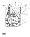
- Figure 1 shows a cross section through a device 1 for Separation of flat packages 10.
- the packages 10 are placed in batches in the magazine 2.
- This magazine is by a stop 7 and a preferably sizing the packages 10 customizable, i. displaceable Wall 6 formed. Is it the packages? For example, to a folded newspaper, the contains more leaflets ("inserts"), the pile is inserted so that the fold on the left, that is the sliding Wall 6 opposite side comes to rest.
- a wall 7 is shown, to the width of the products and thus to the Width of the stack is slidably applied.
- the embodiment The present invention relates with respect to the specified withdrawal drum 3 with gripper 4 the device specified in document EP 0 261 354 B1.
- the device has the withdrawal drum 3, which in the counterclockwise direction rotates.
- At the periphery of the take-off drum 3 at least one actuatable gripper 4 is arranged, the after grasping a package 10 by e.g. suckers 5 of the package detected by a "reverse clamp".
- a package 10 by e.g. suckers 5 of the package detected by a "reverse clamp”.
- suction cups 5 whose position is indicated in FIG. 1 by the reference numeral 5 shown
- the axis of rotation of this pivoting movement is not shown in Fig. 1.
- at least one finger 20 is provided, the between the package to be withdrawn and the next intervenes.
- the fingers 20 and the suction cups 5 provide several times on their respective waves.
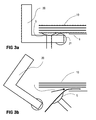
- Fig. 2 shows a detailed structural design of the Finger 20 in a first embodiment.
- the feeder of Air is supplied via hoses connected to an air supply flange 26 are connected to the finger 20.
- Finger 20 points a flange 28 through which a fastener 25th engages to make a firm connection with the shaft 24.
- the screw 23 is here as a closure screw provided, one located inside the finger 20 Air duct closes, the opening is made of manufacturing technology Reasons unavoidable.
- FIG. 2a The location of the air outlet opening 29 and leading to it Air duct 27 is shown in Fig. 2a.
- This Fig. 2a is used to a particular embodiment of the present invention at the tip of the finger 20 may be additional a roller 21 rotatable about an axis 22 may be provided.
- the roller 21 only rotatable in one direction, namely as shown in Fig. 2a in Direction d or clockwise. These possible in one direction Rotatability of the roller 21 is also referred to as a freewheel.
- Fig. 3a is a stationary state before pulling off a Package 10 shown.
- a stack of packages 10 lies on a support 9.
- the denoted by the reference numeral 9 illustrated edition is not the only edition for the Stack.
- the finger 20 about the axis 24 (In Fig. 3a and 3b not shown) down earlier than the Suction cup 5.
- the suction cup 5 pulls the bottom package 10th away from the stack into a position such that a gripper 4 of the Trigger drum 3 can pull the package out of the stack ..
- the finger 20 in the "horizontal" Retracted position (not shown in Figure 3b).
- an air supply approximately in the direction represented by the reference f. It will an air cushion between the two packages concerned 10 generated so that the package to be withdrawn 10 only a very low friction to the immediately above lying package 10 has. This can do that so-called rolling up of the overlying package 10th be very effectively prevented.
- Throughout Movement of the finger 20 may be an air supply. It is also possible to adjust the air supply depending on the location of the Fingers 20 to steer, that is in the downturned Condition to interrupt or at least go back. in the still swung out area of the finger 20 presses the Air flow the package 10 in addition to the suction cup 5.
- the roller 21 therefore has a freewheel, so that at Retraction of the finger and especially in thick Packages 10 of the fingers themselves, the package 10 is not touched and that the role because of its rotation the withdrawal package not exciting or skewered and destroyed by it. Only after deduction of a package 10th through the at least one suction cup 5 is in a later Phase the package 10 by one on the trigger drum. 3 attached gripper 4 detected and further promoted.
- the "blocking" direction of rotation of the roller 21 is the lowest package 10 in the stack close to its pad an additional stop.
- the Fingers 20 may be provided, this only substantially to perform an angle as shown in Figures 3a and 3b is shown.
- This trained as an angle finger also has an air channel 27 and an outlet opening 29 on.
- the air is over the trained as a hollow shaft Shaft 24 is supplied.
Landscapes
- Engineering & Computer Science (AREA)
- Mechanical Engineering (AREA)
- Sheets, Magazines, And Separation Thereof (AREA)
Priority Applications (1)
| Application Number | Priority Date | Filing Date | Title |
|---|---|---|---|
| EP03018299A EP1506931A1 (fr) | 2003-08-12 | 2003-08-12 | Dispositif et méthode pour la séparation des articles postaux plats |
Applications Claiming Priority (1)
| Application Number | Priority Date | Filing Date | Title |
|---|---|---|---|
| EP03018299A EP1506931A1 (fr) | 2003-08-12 | 2003-08-12 | Dispositif et méthode pour la séparation des articles postaux plats |
Publications (1)
| Publication Number | Publication Date |
|---|---|
| EP1506931A1 true EP1506931A1 (fr) | 2005-02-16 |
Family
ID=33560776
Family Applications (1)
| Application Number | Title | Priority Date | Filing Date |
|---|---|---|---|
| EP03018299A Withdrawn EP1506931A1 (fr) | 2003-08-12 | 2003-08-12 | Dispositif et méthode pour la séparation des articles postaux plats |
Country Status (1)
| Country | Link |
|---|---|
| EP (1) | EP1506931A1 (fr) |
Cited By (1)
| Publication number | Priority date | Publication date | Assignee | Title |
|---|---|---|---|---|
| EP2700599A2 (fr) * | 2012-08-22 | 2014-02-26 | Ferag AG | Dispositif et méthode de séparation d'objets plats pliables individuels de la face inférieure d'une pile |
Citations (6)
| Publication number | Priority date | Publication date | Assignee | Title |
|---|---|---|---|---|
| DE1144741B (de) * | 1961-02-17 | 1963-03-07 | Leipziger Buchbindereimaschine | Bogentrenn- und Vereinzelungsvorrichtung |
| GB1525698A (en) * | 1976-08-13 | 1978-09-20 | De La Rue Crosfield | Pneumatic sheet feeding apparatus |
| DE4218203A1 (de) * | 1992-06-03 | 1993-12-09 | Kolbus Gmbh & Co Kg | Vorrichtung zum Vereinzeln von Bogen aus einem Stapelmagazin |
| DE19823649A1 (de) * | 1998-05-27 | 1999-12-02 | Kolbus Gmbh & Co Kg | Vorrichtung zum Vereinzeln von Zuschnitten |
| US6015145A (en) * | 1997-11-03 | 2000-01-18 | Hartel; Siegfried | Separator guide for Z-folded sheets |
| EP1228990A2 (fr) * | 2001-01-31 | 2002-08-07 | Heidelberger Druckmaschinen Aktiengesellschaft | Crochet de levage pour un dispositif de séparation de feuilles |
-
2003
- 2003-08-12 EP EP03018299A patent/EP1506931A1/fr not_active Withdrawn
Patent Citations (6)
| Publication number | Priority date | Publication date | Assignee | Title |
|---|---|---|---|---|
| DE1144741B (de) * | 1961-02-17 | 1963-03-07 | Leipziger Buchbindereimaschine | Bogentrenn- und Vereinzelungsvorrichtung |
| GB1525698A (en) * | 1976-08-13 | 1978-09-20 | De La Rue Crosfield | Pneumatic sheet feeding apparatus |
| DE4218203A1 (de) * | 1992-06-03 | 1993-12-09 | Kolbus Gmbh & Co Kg | Vorrichtung zum Vereinzeln von Bogen aus einem Stapelmagazin |
| US6015145A (en) * | 1997-11-03 | 2000-01-18 | Hartel; Siegfried | Separator guide for Z-folded sheets |
| DE19823649A1 (de) * | 1998-05-27 | 1999-12-02 | Kolbus Gmbh & Co Kg | Vorrichtung zum Vereinzeln von Zuschnitten |
| EP1228990A2 (fr) * | 2001-01-31 | 2002-08-07 | Heidelberger Druckmaschinen Aktiengesellschaft | Crochet de levage pour un dispositif de séparation de feuilles |
Cited By (4)
| Publication number | Priority date | Publication date | Assignee | Title |
|---|---|---|---|---|
| EP2700599A2 (fr) * | 2012-08-22 | 2014-02-26 | Ferag AG | Dispositif et méthode de séparation d'objets plats pliables individuels de la face inférieure d'une pile |
| CN103693466A (zh) * | 2012-08-22 | 2014-04-02 | 费拉格有限公司 | 用于从堆叠件的下侧分离单独、二维、柔性的物件的设备 |
| EP2700599A3 (fr) * | 2012-08-22 | 2014-12-03 | Ferag AG | Dispositif et méthode de séparation d'objets plats pliables individuels de la face inférieure d'une pile |
| US9643805B2 (en) | 2012-08-22 | 2017-05-09 | Ferag Ag | Device for separating individual, two-dimensional, flexible objects from the lower side of a stack |
Similar Documents
| Publication | Publication Date | Title |
|---|---|---|
| EP0514951B1 (fr) | Procédé et dispositif pour fabriquer et transporter des découpes d'emballage | |
| EP0444547B1 (fr) | Méthode et dispositif pour convoyer des bandes de fermeture en vue de les transférer à des paquets | |
| DE3108550C2 (fr) | ||
| DE19519374C2 (de) | Vorrichtung zur automatischen Bogenaussonderung im Ausleger einer Bogenrotationsdruckmaschine | |
| DE3603285C2 (de) | Zusammentragmaschine | |
| EP2253566B1 (fr) | Dispositif de chargement d'une trajectoire de traitement dotée de produits d'impression | |
| EP2841367B1 (fr) | Dispositif permettant de faire se chevaucher et de déposer des feuilles sur une pile | |
| EP0417503B1 (fr) | Procédé et dispositif pour le traitement ultérieur de produits imprimés empilés, de préférence pliés | |
| EP1991484B1 (fr) | Dispositif et procede pour former des piles de produits plats | |
| DE19905263C1 (de) | Vorrichtung und Verfahren zur Probebogenentnahme | |
| DE19515506B4 (de) | Einrichtung zum Verarbeiten von Druckereiprodukten | |
| CH648261A5 (de) | Vorrichtung zum herausloesen von mittels eines foerderers gefoerderten druckprodukten aus dem foerderstrom. | |
| WO2007087858A1 (fr) | Dispositif de freinage de feuilles, notamment de feuilles de papier ou de carton destinées à être déposées sur une pile | |
| DE3330681C2 (fr) | ||
| EP2316766B1 (fr) | Station de déviation pour sections de carton et procédé de fabrication et déviation de sections de carton | |
| EP2133295A1 (fr) | Dispositif et procédé destinés à extraire des produits d'impression plats d'une pile et à les transmettre à un dispositif de transport déroulant | |
| EP0116015B1 (fr) | Dispositif et procédé pour prélever et éloigner un échantillon d'un courant d'articles imprimés imbriqués | |
| DE2720674A1 (de) | Bogenauslegevorrichtung fuer eine rotations-druckmaschine | |
| DE102013101820B4 (de) | Vorrichtung und Verfahren zum Vereinzeln von gestapelten Produkten | |
| DE2244094A1 (de) | Verfahren und vorrichtung zum einlegen folienfoermigen schutzstoffs zwischen tafelfoermiges gut | |
| DE3912026A1 (de) | Verfahren und vorrichtung zum speichern und vereinzeln von spulhuelsen | |
| EP1506931A1 (fr) | Dispositif et méthode pour la séparation des articles postaux plats | |
| EP0806391B1 (fr) | Dispositif pour l'alimentation de produits imprimés vers un autre poste de travail | |
| DE2112353C3 (de) | Verfahren und Vorrichtung zum Trennen einer schuppenförmigen Folge von von einer Schlauchziehmaschine hergestellten Schlauchabschnitten für das Bilden von abgezählten Stapeln | |
| DE4142620C2 (de) | Vorrichtung zum Abziehen von auf Transporttellern aufgesteckten Spulenhülsen |
Legal Events
| Date | Code | Title | Description |
|---|---|---|---|
| PUAI | Public reference made under article 153(3) epc to a published international application that has entered the european phase |
Free format text: ORIGINAL CODE: 0009012 |
|
| AK | Designated contracting states |
Kind code of ref document: A1 Designated state(s): AT BE BG CH CY CZ DE DK EE ES FI FR GB GR HU IE IT LI LU MC NL PT RO SE SI SK TR |
|
| AX | Request for extension of the european patent |
Extension state: AL LT LV MK |
|
| AKX | Designation fees paid | ||
| REG | Reference to a national code |
Ref country code: DE Ref legal event code: 8566 |
|
| STAA | Information on the status of an ep patent application or granted ep patent |
Free format text: STATUS: THE APPLICATION IS DEEMED TO BE WITHDRAWN |
|
| 18D | Application deemed to be withdrawn |
Effective date: 20050817 |