EP1506931A1 - Device and method for separating of flat mail items - Google Patents
Device and method for separating of flat mail items Download PDFInfo
- Publication number
- EP1506931A1 EP1506931A1 EP03018299A EP03018299A EP1506931A1 EP 1506931 A1 EP1506931 A1 EP 1506931A1 EP 03018299 A EP03018299 A EP 03018299A EP 03018299 A EP03018299 A EP 03018299A EP 1506931 A1 EP1506931 A1 EP 1506931A1
- Authority
- EP
- European Patent Office
- Prior art keywords
- packages
- finger
- air
- package
- stack
- Prior art date
- Legal status (The legal status is an assumption and is not a legal conclusion. Google has not performed a legal analysis and makes no representation as to the accuracy of the status listed.)
- Withdrawn
Links
Images

Classifications
-
- B—PERFORMING OPERATIONS; TRANSPORTING
- B65—CONVEYING; PACKING; STORING; HANDLING THIN OR FILAMENTARY MATERIAL
- B65H—HANDLING THIN OR FILAMENTARY MATERIAL, e.g. SHEETS, WEBS, CABLES
- B65H3/00—Separating articles from piles
- B65H3/08—Separating articles from piles using pneumatic force
- B65H3/0808—Suction grippers
- B65H3/085—Suction grippers separating from the bottom of pile
-
- B—PERFORMING OPERATIONS; TRANSPORTING
- B65—CONVEYING; PACKING; STORING; HANDLING THIN OR FILAMENTARY MATERIAL
- B65H—HANDLING THIN OR FILAMENTARY MATERIAL, e.g. SHEETS, WEBS, CABLES
- B65H3/00—Separating articles from piles
- B65H3/46—Supplementary devices or measures to assist separation or prevent double feed
- B65H3/48—Air blast acting on edges of, or under, articles
-
- B—PERFORMING OPERATIONS; TRANSPORTING
- B65—CONVEYING; PACKING; STORING; HANDLING THIN OR FILAMENTARY MATERIAL
- B65H—HANDLING THIN OR FILAMENTARY MATERIAL, e.g. SHEETS, WEBS, CABLES
- B65H2701/00—Handled material; Storage means
- B65H2701/10—Handled articles or webs
- B65H2701/19—Specific article or web
- B65H2701/1916—Envelopes and articles of mail
-
- B—PERFORMING OPERATIONS; TRANSPORTING
- B65—CONVEYING; PACKING; STORING; HANDLING THIN OR FILAMENTARY MATERIAL
- B65H—HANDLING THIN OR FILAMENTARY MATERIAL, e.g. SHEETS, WEBS, CABLES
- B65H2801/00—Application field
- B65H2801/78—Mailing systems
Definitions
- the invention relates to a device and a method for separating flat packages according to the The preamble of claim 1 or of the claim 9th
- the present invention relates to the field of postal automation.
- the separation of flat packages is demanding in that not only the physical sizes of flat packages vary widely, but also the nature of these packages is very different.
- the physical quantities refer to the width, height and thickness, mass and the derived from the material of the packages properties such as coefficient of adhesion or sliding friction.
- the type of packages relates to any packaging and the rigidity of flat packages.
- advertising broadcasts are to be considered here, which are to be found in very different design such as: A simply folded free newspaper, in the fold additional different brochures are inserted.
- the weight of these brochures, these additions are also called “inserts", relative to the newspaper take a considerable extent, since the brochures often provided a much better paper quality. This is also expressed in a correspondingly higher mass per unit area: for example, 120-140 g / m 2 for the leaflets compared with about 40-60 g / m 2 for the newsprint.
- packages are flat packages such as e.g. Letters, brochures, Pattern subsumed in preferably rectangular shape.
- Facilities for the separation of flat packages are for example, known from document EP 1 052 207 A1 (Applicant: Grapha-Holding AG) and EP 1 065 160 A1 (Applicant: Grapha-Holding AG). These are not suitable for the The aforesaid packages, as these are only vertical here Device can be fed. For reasons of relatively high masses the packages considered here and low mechanical Strength of the outer parts such as e.g. a newspaper can this device will not be applied. Therefore, it is required the packages stacked in horizontal layers to feed the device.
- the present invention is therefore based on the object an apparatus and a method for separating packages indicate, regardless of the masses, Proportions and characteristics of the packages a safe Separate and a high throughput is possible. Under safe separation is here in particular the prevention meant by double prints as well as that the packages when singling neither damaged nor unintentionally folded or even destroyed.
- a finger pivotable about a shaft which engages the stack in a package to be removed and has an air outlet at the tip of the finger through which air exits to generate an air cushion between two adjacent packages; a device is created that safely separates packages regardless of their masses, proportions and properties.
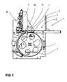
- Figure 1 shows a cross section through a device 1 for Separation of flat packages 10.
- the packages 10 are placed in batches in the magazine 2.
- This magazine is by a stop 7 and a preferably sizing the packages 10 customizable, i. displaceable Wall 6 formed. Is it the packages? For example, to a folded newspaper, the contains more leaflets ("inserts"), the pile is inserted so that the fold on the left, that is the sliding Wall 6 opposite side comes to rest.
- a wall 7 is shown, to the width of the products and thus to the Width of the stack is slidably applied.
- the embodiment The present invention relates with respect to the specified withdrawal drum 3 with gripper 4 the device specified in document EP 0 261 354 B1.
- the device has the withdrawal drum 3, which in the counterclockwise direction rotates.
- At the periphery of the take-off drum 3 at least one actuatable gripper 4 is arranged, the after grasping a package 10 by e.g. suckers 5 of the package detected by a "reverse clamp".
- a package 10 by e.g. suckers 5 of the package detected by a "reverse clamp”.
- suction cups 5 whose position is indicated in FIG. 1 by the reference numeral 5 shown
- the axis of rotation of this pivoting movement is not shown in Fig. 1.
- at least one finger 20 is provided, the between the package to be withdrawn and the next intervenes.
- the fingers 20 and the suction cups 5 provide several times on their respective waves.
- Fig. 2 shows a detailed structural design of the Finger 20 in a first embodiment.
- the feeder of Air is supplied via hoses connected to an air supply flange 26 are connected to the finger 20.
- Finger 20 points a flange 28 through which a fastener 25th engages to make a firm connection with the shaft 24.
- the screw 23 is here as a closure screw provided, one located inside the finger 20 Air duct closes, the opening is made of manufacturing technology Reasons unavoidable.
- FIG. 2a The location of the air outlet opening 29 and leading to it Air duct 27 is shown in Fig. 2a.
- This Fig. 2a is used to a particular embodiment of the present invention at the tip of the finger 20 may be additional a roller 21 rotatable about an axis 22 may be provided.
- the roller 21 only rotatable in one direction, namely as shown in Fig. 2a in Direction d or clockwise. These possible in one direction Rotatability of the roller 21 is also referred to as a freewheel.
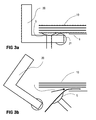
- Fig. 3a is a stationary state before pulling off a Package 10 shown.
- a stack of packages 10 lies on a support 9.
- the denoted by the reference numeral 9 illustrated edition is not the only edition for the Stack.
- the finger 20 about the axis 24 (In Fig. 3a and 3b not shown) down earlier than the Suction cup 5.
- the suction cup 5 pulls the bottom package 10th away from the stack into a position such that a gripper 4 of the Trigger drum 3 can pull the package out of the stack ..
- the finger 20 in the "horizontal" Retracted position (not shown in Figure 3b).
- an air supply approximately in the direction represented by the reference f. It will an air cushion between the two packages concerned 10 generated so that the package to be withdrawn 10 only a very low friction to the immediately above lying package 10 has. This can do that so-called rolling up of the overlying package 10th be very effectively prevented.
- Throughout Movement of the finger 20 may be an air supply. It is also possible to adjust the air supply depending on the location of the Fingers 20 to steer, that is in the downturned Condition to interrupt or at least go back. in the still swung out area of the finger 20 presses the Air flow the package 10 in addition to the suction cup 5.
- the roller 21 therefore has a freewheel, so that at Retraction of the finger and especially in thick Packages 10 of the fingers themselves, the package 10 is not touched and that the role because of its rotation the withdrawal package not exciting or skewered and destroyed by it. Only after deduction of a package 10th through the at least one suction cup 5 is in a later Phase the package 10 by one on the trigger drum. 3 attached gripper 4 detected and further promoted.
- the "blocking" direction of rotation of the roller 21 is the lowest package 10 in the stack close to its pad an additional stop.
- the Fingers 20 may be provided, this only substantially to perform an angle as shown in Figures 3a and 3b is shown.
- This trained as an angle finger also has an air channel 27 and an outlet opening 29 on.
- the air is over the trained as a hollow shaft Shaft 24 is supplied.
Landscapes
- Engineering & Computer Science (AREA)
- Mechanical Engineering (AREA)
- Sheets, Magazines, And Separation Thereof (AREA)
Abstract
Description
Die Erfindung bezieht sich auf eine Vorrichtung und ein Verfahren
zum Vereinzeln von flachen Versandstücken gemäss dem
Oberbegriff des Patentanspruches 1 bzw. des Patentanspruches
9.The invention relates to a device and a method
for separating flat packages according to the
The preamble of
Die vorliegende Erfindung betrifft das Gebiet der Postautomation. Zur automatisierten Verteilung von flachen Versandstücken wie Briefe oder Prospekte werden diese innerhalb eines Postverteilzentrums mittels Förderbahnen und/oder Förderbändern zu ihren Zielstellen - auch Bestimmungsorte genannt - transportiert.The present invention relates to the field of postal automation. For the automated distribution of flat packages like letters or leaflets, these are within a mail distribution center by means of conveyor tracks and / or conveyor belts to their destinations - also called destinations - transported.
Die Vereinzelung von flachen Versandstücken ist insofern anspruchsvoll,
weil nicht nur die physikalischen Grössen von
flachen Versandstücken in weiten Grenzen schwanken, sondern
auch die Art dieser Versandstücke sehr verschieden ist. Die
physikalischen Grössen beziehen sich auf die Breite, Höhe und
Dicke, Masse und der aus dem Material der Versandstücke abzuleitenden
Eigenschaften wie z.B. Haft- oder Gleitreibungskoeffizient.
Die Art der Versandstücke betrifft eine eventuell
vorhandene Verpackung und die Steifigkeit flacher Versandstücke.
Im besonderen sind hier Werbesendungen zu berücksichtigen,
die in sehr unterschiedlicher Ausgestaltung anzutreffen
sind wie beispielsweise:
Eine einfach gefaltete Gratiszeitung, in deren Falt zusätzliche
unterschiedliche Prospekte eingelegt sind. Dabei kann das
Gewicht dieser Prospekte, man nennt diese Beigaben auch "inserts",
relativ zur Zeitung ein beträchtliches Ausmass annehmen,
da für die Prospekte oft eine wesentlich bessere
Papierqualität vorgesehen ist. Dies drückt sich auch in einem
entsprechend höheren Masse pro Flächeneinheit aus: Z.B. 120 -
140 g/m2 für die Prospekte gegenüber etwa 40 - 60 g/m2 für
das Zeitungspapier. The separation of flat packages is demanding in that not only the physical sizes of flat packages vary widely, but also the nature of these packages is very different. The physical quantities refer to the width, height and thickness, mass and the derived from the material of the packages properties such as coefficient of adhesion or sliding friction. The type of packages relates to any packaging and the rigidity of flat packages. In particular, advertising broadcasts are to be considered here, which are to be found in very different design such as:
A simply folded free newspaper, in the fold additional different brochures are inserted. The weight of these brochures, these additions are also called "inserts", relative to the newspaper take a considerable extent, since the brochures often provided a much better paper quality. This is also expressed in a correspondingly higher mass per unit area: for example, 120-140 g / m 2 for the leaflets compared with about 40-60 g / m 2 for the newsprint.
Im Sinne dieser Schrift ist nunmehr zur Vereinfachung nur von Versandstücken die Rede, unter diesen Begriff "Versandstücken" sind flache Versandstücke wie z.B. Briefe, Prospekte, Muster in vorzugsweise rechteckiger Form subsummiert.For the purposes of this document is now for simplicity only by Packages the speech, under this term "packages" are flat packages such as e.g. Letters, brochures, Pattern subsumed in preferably rectangular shape.
Einrichtungen zur Vereinzelung von flachen Versandstücke sind
beispielsweise bekannt aus den Schrift EP 1 052 207 A1 (Anmelderin:
Grapha-Holding AG) und EP 1 065 160 A1 (Anmelderin:
Grapha-Holding AG). Diese eignen sich jedoch nicht für die
vorgenannte Versandstücke, da diese hier nur vertikal der
Vorrichtung zuführbar sind. Aus Gründen relativ hoher Massen
der hier betrachteten Versandstücke und geringer mechanischer
Festigkeit der äusseren Teile wie z.B. eine Zeitung kann
diese Vorrichtung nicht angewendet werden. Gefordert ist daher,
die Versandstücke stapelweise in horizontal geschichtet
der Vorrichtung zuzuführen.Facilities for the separation of flat packages are
for example, known from
Eine solche Vorrichtung ist bekannt aus EP 0 261 354 B1 (Patentinhaberin: Grapha-Holding AG). Dabei werden die Versandstücke von einer Abzugstrommel im wesentlichen in horizontaler Lage vereinzelt mit Greifern erfasst und wegführt. Mit dieser Vorrichtung lassen sich dank der Dickenmessung beispielsweise Doppelabzüge detektieren. Durch die Dickenmessung wird jedoch das Problem, dass sich ein gefaltetes Versandstück vom unmittelbar vorangehenden wegen der Reibung dazwischen "aufgerollt" wird, nicht gelöst. Dieses "Aufrollen" hat in aller Regel eine Beschädigung wenn nicht gar Zerstörung des betreffenden Versandstückes zur Folge, darüber hinaus wird der Vereinzelungsprozess unterbrochen.Such a device is known from EP 0 261 354 B1 (Patent owner: Grapha-Holding AG). This will be the packages from a haul-off drum substantially in horizontal Occasionally seized with grippers and leads away. With this device can be thanks to the thickness measurement For example, detect double prints. By the thickness measurement However, the problem is that a folded Package of immediately preceding due to friction in between "rolled up" is not solved. This "rolling up" usually has damage if not all Destruction of the package in question, about In addition, the singulation process is interrupted.
Der vorliegenden Erfindung liegt daher die Aufgabe zugrunde eine Vorrichtung und ein Verfahren zur Vereinzelung von Versandstücken anzugeben, bei denen unabhängig von den Massen, Proportionen und Eigenschaften der Versandstücke ein sicheres Vereinzeln und ein hoher Durchsatz ermöglicht wird. Unter sicherem Vereinzeln ist hier im besonderen die Verhinderung von Doppelabzügen gemeint wie auch dass die Versandstücke beim Vereinzeln weder beschädigt oder noch ungewollt gefaltet oder gar zerstört werden.The present invention is therefore based on the object an apparatus and a method for separating packages indicate, regardless of the masses, Proportions and characteristics of the packages a safe Separate and a high throughput is possible. Under safe separation is here in particular the prevention meant by double prints as well as that the packages when singling neither damaged nor unintentionally folded or even destroyed.
Diese Aufgabe wird erfindungsgemäss durch die im Patentanspruch
1 angegebene Vorrichtung und durch das im Patentanspruch
9 angegebene Verfahren gelöst.This object is achieved by the in the
Durch die erfindungsgemässe Lösung, wonach
ein um eine Welle schwenkbarer Finger vorgesehen ist, der bei
einem wegzuführenden Versandstück in den Stapel eingreift und
an der Spitze des Fingers eine Luftaustrittsöffnung aufweist,
durch die Luft austritt um zwischen zwei aneinanderliegenden
Versandstücken ein Luftpolster zu generieren;
ist eine Vorrichtung geschaffen, die Versandstücke unabhängig
von ihren Massen, Proportionen und Eigenschaften sicher vereinzelt.By the inventive solution, according to which
a finger pivotable about a shaft is provided which engages the stack in a package to be removed and has an air outlet at the tip of the finger through which air exits to generate an air cushion between two adjacent packages;
a device is created that safely separates packages regardless of their masses, proportions and properties.
Vorteilhafte Ausgestaltungen der Erfindung sind in weiteren
Ansprüchen angegeben.
an der Spitze des Fingers eine Rolle vorgesehen ist, auf der das Versandstück vor Erfassung durch die Abzugstrommel aufliegt;
erfahren die abzuziehenden Versandstücke keine Beschädigung bei einer allfälligen Berührung mit dem Finger bei dessen Zurückschwenken (Patentanspruch 2).
sind keine zusätzlichen Komponenten in der Umgebung der
Spitze des Fingers vorhanden, die ggf. mit den abzuziehenden Versandstücken kollidieren könnten.
die Welle als Hohlwelle ausgebildet ist und dass der Luftkanal mit der Hohlwelle verbunden ist;
sind keine zusätzliche Komponenten dem durch die Bewegungen verursachten Beanspruchung ausgesetzt. (Patentanspruch 7).
at the tip of the finger, a roller is provided on which the package rests before being detected by the trigger drum;
learn the packages to be deducted no damage in case of any contact with the finger during its pivoting back (claim 2).
are no additional components in the environment of
Tip of the finger available, which could possibly collide with the packages to be deducted.
the shaft is formed as a hollow shaft and that the air duct is connected to the hollow shaft;
No additional components are exposed to the stress caused by the movements. (Claim 7).
Die Erfindung wird nachfolgend anhand einer Zeichnung beispielsweise näher erläutert. Dabei zeigen:
Figur 1- Querschnitt durch eine Vorrichtung zur Vereinzelung;
Figur 2- Querschnitt eines Fingers einer Vorrichtung zur Vereinzelung von flachen Versandstücken;
- Figur 2a
- Detailansicht eines in Fig. 2 dargestellten Fingers;
- Figur 3a
- Lage des Fingers vor Abzug eines Versandstückes;
- Figur 3a
- Lage des Fingers während dem Abzug eines Fingers.
- FIG. 1
- Cross section through a device for separation;
- FIG. 2
- Cross section of a finger of a device for separating flat packages;
- FIG. 2a
- Detailed view of a finger shown in Fig. 2;
- FIG. 3a
- Position of the finger before deduction of a package;
- FIG. 3a
- Position of the finger during the withdrawal of a finger.
Figur 1 zeigt einen Querschnitt durch eine Vorrichtung 1 zur
Vereinzelung von flachen Versandstücken 10. Die Versandstücke
10 werden stapelweise in das Magazin 2 gelegt. Dieses Magazin
wird durch einen Anschlag 7 und eine vorzugsweise an die Dimensionierung
der Versandstücke 10 anpassbare, d.h. verschiebbare
Wand 6 gebildet. Handelt es sich bei den Versandstücken
10 beispielsweise um einen gefaltete Zeitung, die
noch weitere Prospekte ("inserts") enthält, wird der Stapel
so eingelegt dass der Falt links, das heisst der der verschiebbaren
Wand 6 gegenüberliegenden Seite zu liegen kommt.
In der Darstellung gemäss der Fig. 1 ist eine Wand 7 dargestellt,
die an die Breite der Produkte und somit an die
Breite des Stapels verschiebbar anlegbar ist. Das Ausführungsbeispiel
der vorliegenden Erfindung bezieht sich
bezüglich der angegebenen Abzugstrommel 3 mit Greifer 4 auf
die in der Schrift EP 0 261 354 B1 angegebene Vorrichtung.Figure 1 shows a cross section through a
Die Vorrichtung weist die Abzugstrommel 3 auf, die im Gegenuhrzeigersinn
dreht. An der Peripherie der Abzugstrommel 3
ist wenigstens ein betätigbarer Greifer 4 angeordnet, der
nach dem Fassen eines Versandstückes 10 durch z.B. Saugnäpfe
5 des Versandstück durch ein "Rückwärtsklemmen" erfasst. Vor
diesem Erfassen wird in dieser Ausführungsform das Versandstück
durch Saugnäpfe 5 (deren Lage ist in Fig. 1 mit dem Bezugszeichen
5 dargestellt) erfasst und durch Schenken der
Saugnäpfe 5 nach unten gezogen. Die Drehachse dieser Schwenkbewegung
ist in Fig. 1 nicht dargestellt. Zur besseren Vereinzelung
ist nun mindestens ein Finger 20 vorgesehen, der
zwischen dem abzuziehenden und dem nächstfolgenden Versandstück
eingreift. Um beim Abziehen des untersten Versandstückes
10 die Reibung dazwischen zu reduzieren weist dieser
Finger 20 erfindungsgemäss eine Luftaustrittsöffnung 29 auf,
durch die Luft ausströmt, um die vorgenannten zwei Versandstücke
10 besser zu separieren und dadurch die beim Abzug
zwangsläufig vorhandene Reibung deutlich zu reduzieren. Die
Schwenkbewegung des Fingers 20 ist unabhängig von der
Schwenkbewegung des vorgenannten Saugnapfes 5, erfolgt jedoch
synchronisiert mit der Bewegung des Saugnapfes 5; siehe dazu
dien nachfolgenden Ausführungen zu den Figuren 3a und 3b..The device has the
Besonders vorteilhaft ist es, die Finger 20 und die Saugnäpfe
5 auf ihren betreffenden Wellen mehrfach vorzusehen.It is particularly advantageous, the
Fig. 2 zeigt eine detaillierte konstruktive Ausgestaltung des
Fingers 20 in einer ersten Ausführungsform. Die Zuführung der
Luft erfolgt dabei über Schläuche, die an einen Luftzuführflansch
26 mit dem Finger 20 verbunden sind. Finger 20 weist
einen Flansch 28 auf, durch den ein Befestigungsmittel 25
eingreift, um eine feste Verbindung mit der Welle 24 herzustellen.
Die Schraube 23 ist hier als Verschluss-Schraube
vorgesehen, die einen im Innern des Fingers 20 befindlichen
Luftkanal abschliesst, die Öffnung dazu ist aus fertigungstechnischen
Gründen nicht vermeidbar.Fig. 2 shows a detailed structural design of the
Die Lage der Luftaustrittsöffnung 29 und des dazu führenden
Luftkanals 27 ist in Fig. 2a gezeigt. Diese Fig. 2a wird benutzt,
um eine besondere Weiterbildung der vorliegenden Erfindung
darzulegen: An der Spitze des Fingers 20 kann zusätzlich
eine um eine Achse 22 drehbare Rolle 21 vorgesehen sein. The location of the
Dabei ist in einer besonderen Weiterbildung die Rolle 21 nur
in einer Richtung drehbar, nämlich wie in Fig. 2a gezeigt in
Richtung d bzw. im Uhrzeigersinn. Diese in eine Richtung mögliche
Drehbarkeit der Rolle 21 wird auch als Freilauf bezeichnet.In this case, in a particular embodiment, the
Die Funktion dieser Rolle 21 wie auch der Bewegungsablauf des
Fingers 20 wird anhand der Figuren 3a und 3b erläutert:
In Fig. 3a ist ein stationärer Zustand vor dem Abziehen eines
Versandstückes 10 dargestellt. Ein Stapel von Versandstücken
10 liegt auf einer Auflage 9. Die mit dem Bezugszeichen 9
dargestellte Auflage ist nicht die einzige Auflage für den
Stapel. Für das Abziehen des untersten Versandstückes 10 bewegt
sich zunächst der Finger 20 um die Achse 24 (In Fig. 3a
und 3b nicht dargestellt) nach unten und zwar früher als der
Saugnapf 5. Der Saugnapf 5 zieht das unterste Versandstück 10
vom Stapel weg in eine Position so, dass ein Greifer 4 der
Abzugstrommel 3 das Versandstück aus dem Stapel ziehen kann..
Anschliessend wird der Finger 20 in die "horizontale"
Position zurückgefahren (in Figur 3b nicht dargestellt). Beim
Zurückfahren erfolgt dabei eine Luftzufuhr ungefähr in der
mit dem Bezugszeichen f dargestellten Richtung. Dabei wird
ein Luftpolster zwischen den beiden betreffenden Versandstücken
10 generiert, so dass das abzuziehende Versandstück
10 nur noch eine sehr geringe Reibung zum unmittelbar darüber
liegenden Versandstück 10 aufweist. Dadurch kann das
sogenannte Aufrollen des darüber liegenden Versandstückes 10
sehr wirksam verhindert werden. Während dem ganzen
Bewegungsablauf des Fingers 20 kann eine Luftzufuhr erfolgen.
Möglich ist es auch, die Luftzufuhr abhängig von der Lage des
Fingers 20 zu steuern, das heisst im nach unten geschwenkten
Zustand zu unterbrechen oder wenigstens zurückzufahren. Im
noch ausgeschwenkten Bereich des Fingers 20 drückt der
Luftstrom das Versandstück 10 zusätzlich gegen den Saugnapf
5. Die Rolle 21 weist deshalb einen Freilauf auf, damit beim
Zurückfahren des Fingers und vor allem bei dicken
Versandstücken 10 der Finger selber das Versandstück 10 nicht
berührt und dass die Rolle wegen ihrer Drehbarkeit das
abziehende Versandstück nicht aufreist bzw. aufspiesst und
dadurch zerstört. Erst nach Abzug eines Versandstückes 10
durch den mindestens einen Saugnapf 5 wird in einer späteren
Phase das Versandstück 10 durch einen auf der Abzugstrommel 3
befestigten Greifer 4 erfasst und weiter gefördert.The function of this
Die "blockierende" Drehrichtung der Rolle 21 ist gibt dem
untersten Versandstück 10 im Stapel nahe an dessen Auflage
einen zusätzlichen Halt.The "blocking" direction of rotation of the
In einer zweiten besonders vorteilhaften Ausführungsform des
Fingers 20 kann vorgesehen sein, diesen lediglich im wesentlichen
winkelförmig auszuführen wie dies in den Figuren 3a
und 3b dargestellt ist. Dieser als Winkel ausgebildete Finger
weist ebenfalls einen Luftkanal 27 und eine Austrittsöffnung
29 auf. Die Luft wird dabei über die als Hohlwelle ausgebildete
Welle 24 zugeführt. Dies hat den grossen Vorteil
einerseits eines einfacher herzustellenden Fingers 20 zu ermöglichen
und andererseits, dass die weniger Teile den durch
für die Schwenkbewegung erforderlichen hohen Winkelbeschleunigungen
ausgesetzt sind. Dies betriff insbesondere die Luftschläuche,
die dadurch einem Verschleiss ausgesetzt sind. In a second particularly advantageous embodiment of the
- 11
- Vorrichtung zur Vereinzelung von Versandstücken, im Stand der Technik auch Bogenanleger genanntDevice for separating packages, in State of the art also called sheet feeder
- 22
- Magazin für gestapelte VersandstückeMagazine for stacked packages
- 33
- Greifertrommel, AbzugstrommelGripper drum, take-off drum
- 44
- Greifer auf GreifertrommelGripper on gripper drum
- 55
- Lage der Saugnäpfe, SaugnäpfePosition of the suction cups, suction cups
- 66
- Wand, verschiebbar, anpassbar an ProduktlängeWall, movable, adaptable to product length
- 77
- Wand, verschiebbar, anpassbar an ProduktbreiteWall, movable, adaptable to product width
- 1010
- Versandstück, VersandstückePackage, packages
- 2020
- Fingerfinger
- 2121
- Rolle, Rolle mit FreilaufRoll, reel with freewheel
- 2222
- Drehachse der RolleRotary axis of the roll
- 2323
- VerschlussschraubeScrew
- 2424
- Welle, HohlwelleShaft, hollow shaft
- 2525
- Befestigungsschraubefixing screw
- 2626
- LuftzuführflanschLuftzuführflansch
- 2727
-
Luftkanal im Finger 20Air channel in the
finger 20 - 2828
-
Flansch, als Teil des Fingers 20Flange, as part of the
finger 20 - 2929
- LuftaustrittsöffnungAir outlet opening
- dd
-
Drehrichtung der Rolle 21 im FreilaufDirection of rotation of the
roller 21 in the freewheel - ff
- Luftströmungairflow
Claims (9)
dadurch gekennzeichnet, dass
ein um eine Welle (24) schwenkbarer Finger (20) vorgesehen ist, der bei einem wegzuführenden Versandstück (10) in den Stapel eingreift und eine Luftaustrittsöffnung (29) aufweist, durch die Luft austritt um zwischen zwei aneinanderliegenden Versandstücken (10) ein Luftpolster zu generieren.Device (1) for separating flat packages (10), in which the packages (10) are stored in a stack in a magazine (2) and can be lead away by a withdrawal drum (3) in individual cases,
characterized in that
a pivotable about a shaft (24) finger (20) is provided, which engages in a wegzuführenden package (10) in the stack and an air outlet opening (29) through the air exits to between two adjacent packages (10) an air cushion to generate.
dadurch gekennzeichnet, dass
die Luftaustrittsöffnung (29) an der Spitze des Fingers angeordnet ist.Apparatus according to claim 1;
characterized in that
the air outlet opening (29) is arranged at the tip of the finger.
dadurch gekennzeichnet, dass
an der Spitze des Fingers (20) eine Rolle (21) vorgesehen ist, auf der das Versandstück (10) vor Erfassung durch die Abzugstrommel (3) aufliegt.Apparatus according to claim 2;
characterized in that
at the tip of the finger (20) a roller (21) is provided, on which the package (10) rests before detection by the withdrawal drum (3).
dadurch gekennzeichnet, dass
die Rolle (21) nur in einer Drehrichtung drehbar ist, um das zu vereinzelnde Versandstück (10) durch das Zurückschwenken des Fingers (20) nicht zu beschädigen und um eingeschwenkten Zustand eine bessere Halterung der Versandstücke (10) sicherzustellen.Apparatus according to claim 3;
characterized in that
the roller (21) is rotatable only in one direction of rotation, in order not to damage the package (10) to be separated by the pivoting back of the finger (20) and to ensure a better holding of the packages (10) in the swung-in state.
dadurch gekennzeichnet, dass
mehrere Finger (20) in einem Abstand auf der Welle (24) angeordnet sind und synchron schwenkbar sind.Device according to one of claims 1 to 4,
characterized in that
a plurality of fingers (20) are arranged at a distance on the shaft (24) and are synchronously pivotable.
dadurch gekennzeichnet, dass
der Finger (20) einen Luftkanal (27) enthält, der in die Luftaustrittsöffnung (29) mündet.Device according to one of claims 1 to 5;
characterized in that
the finger (20) contains an air channel (27) which opens into the air outlet opening (29).
dadurch gekennzeichnet, dass
der Finger (20) einen Luftzuführflansch (26) aufweist, an den ein Luftschlauch anschliessbar ist.Device according to claim 6,
characterized in that
the finger (20) has an air supply flange (26) to which an air hose can be connected.
dadurch gekennzeichnet, dass
die Welle (24) als Hohlwelle ausgebildet ist und dass der Luftkanal (27) mit der Hohlwelle verbunden ist.Device according to claim 7,
characterized in that
the shaft (24) is designed as a hollow shaft and that the air channel (27) is connected to the hollow shaft.
dadurch gekennzeichnet, dass
zwischen dem wegzuführenden Versandstück (10) und dem darüber liegenden Versandstück (10) ein Luftpolster durch Zuführung von Luft erzeugt wird, wobei die Luft durch eine zwischen den vorgenannten Versandstücken (10) platzierbare Luftaustrittöffnung (29) zugeführt wird, um zwei aneinanderliegende Versandstücke (10) leichter zu separieren.Method for separating flat packages (10), in which the packages (10) are stored in a stack in a magazine (2) and are led away in isolated fashion by a withdrawal drum (3),
characterized in that
an air cushion is produced by supplying air between the package (10) to be carried away and the overlying package (10), the air being fed through an air outlet opening (29) which can be placed between the aforementioned packages (10) to form two contiguous packages (10 ) easier to separate.
Priority Applications (1)
| Application Number | Priority Date | Filing Date | Title |
|---|---|---|---|
| EP03018299A EP1506931A1 (en) | 2003-08-12 | 2003-08-12 | Device and method for separating of flat mail items |
Applications Claiming Priority (1)
| Application Number | Priority Date | Filing Date | Title |
|---|---|---|---|
| EP03018299A EP1506931A1 (en) | 2003-08-12 | 2003-08-12 | Device and method for separating of flat mail items |
Publications (1)
| Publication Number | Publication Date |
|---|---|
| EP1506931A1 true EP1506931A1 (en) | 2005-02-16 |
Family
ID=33560776
Family Applications (1)
| Application Number | Title | Priority Date | Filing Date |
|---|---|---|---|
| EP03018299A Withdrawn EP1506931A1 (en) | 2003-08-12 | 2003-08-12 | Device and method for separating of flat mail items |
Country Status (1)
| Country | Link |
|---|---|
| EP (1) | EP1506931A1 (en) |
Cited By (1)
| Publication number | Priority date | Publication date | Assignee | Title |
|---|---|---|---|---|
| EP2700599A2 (en) * | 2012-08-22 | 2014-02-26 | Ferag AG | Device and method for separating individual flat, flexible objects from the underside of a stack |
Citations (6)
| Publication number | Priority date | Publication date | Assignee | Title |
|---|---|---|---|---|
| DE1144741B (en) * | 1961-02-17 | 1963-03-07 | Leipziger Buchbindereimaschine | Sheet separating and separating device |
| GB1525698A (en) * | 1976-08-13 | 1978-09-20 | De La Rue Crosfield | Pneumatic sheet feeding apparatus |
| DE4218203A1 (en) * | 1992-06-03 | 1993-12-09 | Kolbus Gmbh & Co Kg | Sorting out individual sheets from stacking magazine - using blow nozzle to produce air jet to separate double sheet through rail supporting sheet stack |
| DE19823649A1 (en) * | 1998-05-27 | 1999-12-02 | Kolbus Gmbh & Co Kg | Machine for continuous separation of paper material blanks, such as book covering material, or flexible covers for brochures, for example |
| US6015145A (en) * | 1997-11-03 | 2000-01-18 | Hartel; Siegfried | Separator guide for Z-folded sheets |
| EP1228990A2 (en) * | 2001-01-31 | 2002-08-07 | Heidelberger Druckmaschinen Aktiengesellschaft | Lifting hook for a sheet separation device |
-
2003
- 2003-08-12 EP EP03018299A patent/EP1506931A1/en not_active Withdrawn
Patent Citations (6)
| Publication number | Priority date | Publication date | Assignee | Title |
|---|---|---|---|---|
| DE1144741B (en) * | 1961-02-17 | 1963-03-07 | Leipziger Buchbindereimaschine | Sheet separating and separating device |
| GB1525698A (en) * | 1976-08-13 | 1978-09-20 | De La Rue Crosfield | Pneumatic sheet feeding apparatus |
| DE4218203A1 (en) * | 1992-06-03 | 1993-12-09 | Kolbus Gmbh & Co Kg | Sorting out individual sheets from stacking magazine - using blow nozzle to produce air jet to separate double sheet through rail supporting sheet stack |
| US6015145A (en) * | 1997-11-03 | 2000-01-18 | Hartel; Siegfried | Separator guide for Z-folded sheets |
| DE19823649A1 (en) * | 1998-05-27 | 1999-12-02 | Kolbus Gmbh & Co Kg | Machine for continuous separation of paper material blanks, such as book covering material, or flexible covers for brochures, for example |
| EP1228990A2 (en) * | 2001-01-31 | 2002-08-07 | Heidelberger Druckmaschinen Aktiengesellschaft | Lifting hook for a sheet separation device |
Cited By (4)
| Publication number | Priority date | Publication date | Assignee | Title |
|---|---|---|---|---|
| EP2700599A2 (en) * | 2012-08-22 | 2014-02-26 | Ferag AG | Device and method for separating individual flat, flexible objects from the underside of a stack |
| CN103693466A (en) * | 2012-08-22 | 2014-04-02 | 费拉格有限公司 | Device for separating individual flat, flexible objects from the underside of a stack |
| EP2700599A3 (en) * | 2012-08-22 | 2014-12-03 | Ferag AG | Device and method for separating individual flat, flexible objects from the underside of a stack |
| US9643805B2 (en) | 2012-08-22 | 2017-05-09 | Ferag Ag | Device for separating individual, two-dimensional, flexible objects from the lower side of a stack |
Similar Documents
| Publication | Publication Date | Title |
|---|---|---|
| EP0514951B1 (en) | Method and device for fabricating and conveying packaging blanks | |
| EP0444547B1 (en) | Method and device for conveying closing strips in order to transfer them to packages | |
| DE3108550C2 (en) | ||
| DE19519374C2 (en) | Device for automatic sheet separation in the delivery of a sheet-fed rotary printing machine | |
| DE3603285C2 (en) | Gathering machine | |
| EP2253566B1 (en) | Device for feeding a processing line with printed products | |
| EP2841367B1 (en) | Apparatus for imbricating sheets and depositing them on a stack | |
| EP0417503B1 (en) | Method and means for handling piled, preferably folded printed products | |
| EP1991484B1 (en) | Apparatus and method for forming stacks of flat products | |
| DE19905263C1 (en) | System for removing test sheets from a printing press | |
| DE19515506B4 (en) | Device for processing printed products | |
| CH648261A5 (en) | DEVICE FOR RELEASING PRINTED PRODUCTS CONTAINED BY A CONVEYOR FROM THE CONVEYOR. | |
| WO2007087858A1 (en) | Apparatus for decelerating sheets to be stacked, especially paper or cardboard sheets | |
| DE3330681C2 (en) | ||
| EP2316766B1 (en) | Diverter station for cardboard blanks and method for producing and diverting cardboard blanks | |
| EP2133295A1 (en) | Device and method for removing flat print products from a pile and transferring the print products to a running transport device | |
| EP0116015B1 (en) | Device and method for removing and diverting a sample from a stream of overlapping printed articles | |
| DE2720674A1 (en) | Sheet feed for rotary printing press - has gripper system and stop with blower at laying-up point | |
| DE102013101820B4 (en) | Apparatus and method for separating stacked products | |
| DE2244094A1 (en) | METHOD AND DEVICE FOR INSERTING FILM-SHAPED PROTECTIVE MATERIAL BETWEEN TABLE-SHAPED GOODS | |
| DE3912026A1 (en) | METHOD AND DEVICE FOR STORING AND SEPARATING COIL CASES | |
| EP1506931A1 (en) | Device and method for separating of flat mail items | |
| EP0806391B1 (en) | Device for feeding printed articles to a further work station | |
| DE2112353C3 (en) | Method and device for separating an imbricated sequence of tube sections produced by a tube drawing machine for the formation of counted stacks | |
| DE4142620C2 (en) | Device for removing coil sleeves attached to transport plates |
Legal Events
| Date | Code | Title | Description |
|---|---|---|---|
| PUAI | Public reference made under article 153(3) epc to a published international application that has entered the european phase |
Free format text: ORIGINAL CODE: 0009012 |
|
| AK | Designated contracting states |
Kind code of ref document: A1 Designated state(s): AT BE BG CH CY CZ DE DK EE ES FI FR GB GR HU IE IT LI LU MC NL PT RO SE SI SK TR |
|
| AX | Request for extension of the european patent |
Extension state: AL LT LV MK |
|
| AKX | Designation fees paid | ||
| REG | Reference to a national code |
Ref country code: DE Ref legal event code: 8566 |
|
| STAA | Information on the status of an ep patent application or granted ep patent |
Free format text: STATUS: THE APPLICATION IS DEEMED TO BE WITHDRAWN |
|
| 18D | Application deemed to be withdrawn |
Effective date: 20050817 |