EP1504639B1 - Outil d'ameublissement du sol avec système d'échange rapide - Google Patents
Outil d'ameublissement du sol avec système d'échange rapide Download PDFInfo
- Publication number
- EP1504639B1 EP1504639B1 EP04018455A EP04018455A EP1504639B1 EP 1504639 B1 EP1504639 B1 EP 1504639B1 EP 04018455 A EP04018455 A EP 04018455A EP 04018455 A EP04018455 A EP 04018455A EP 1504639 B1 EP1504639 B1 EP 1504639B1
- Authority
- EP
- European Patent Office
- Prior art keywords
- share
- plough
- support
- cultivator tine
- plough share
- Prior art date
- Legal status (The legal status is an assumption and is not a legal conclusion. Google has not performed a legal analysis and makes no representation as to the accuracy of the status listed.)
- Not-in-force
Links
Images


Classifications
-
- A—HUMAN NECESSITIES
- A01—AGRICULTURE; FORESTRY; ANIMAL HUSBANDRY; HUNTING; TRAPPING; FISHING
- A01B—SOIL WORKING IN AGRICULTURE OR FORESTRY; PARTS, DETAILS, OR ACCESSORIES OF AGRICULTURAL MACHINES OR IMPLEMENTS, IN GENERAL
- A01B35/00—Other machines for working soil not specially adapted for working soil on which crops are growing
- A01B35/20—Tools; Details
- A01B35/22—Non-rotating tools; Resilient or flexible mounting of rigid tools
- A01B35/225—Non-rotating tools; Resilient or flexible mounting of rigid tools the tools being adapted to allow the chisel point to be easily fitted or removed from the shank
Definitions
- the invention relates to a soil cultivator, the cultivator tines each consisting of a holding stem with share holder, a center crowd and wing shares.
- the middle share can be formed from share point and baffle or as a turn share.
- a turnaround consists of a baffle arranged at both ends Scharspitzen so that the crowd can be reversed after wear of a share tip.
- Bodengrubber the just mentioned genus can be equipped with one or more parts flocks.
- the share is formed by a correspondingly shaped one-piece Scharblatt, which is mounted on the share holder of the holding style.
- the center coulter and coulter wing are designed as separate coulter parts and mounted on the coulter holder.
- one-piece wing shares have the disadvantage that the achieved in the soil cultivation mixing of the soil with respect to multi-part flocks with leading share tip is not satisfactory and standing under Veschl altern Scharmaschine are not individually interchangeable.
- Multi-part coulters result in a better mixing of the soil and thus a better work result.
- Multi-part flocks not only have the advantage that the much faster-wearing leading share tip of the center crowd is individually interchangeable, but also the advantage that the cultivator tines are used either in the complete equipment with center flock and flock wings or after dismantling the flock wings only with the center flock alone can.
- the use of the soil cultivator with center blade and flock wings is done for the flat tillage, while at the lower Tillage the flocks dismantled (or replaced by another Scharform), because otherwise an excessive power requirement would be necessary.
- the invention is therefore an object of the invention to provide a cultivator tines with multi-part share system, which is suitable for both shallow and deep tillage with good soil mixing result and can be retrofitted with little effort.
- the inventive arrangement a quick and cost-effective change of the individual circuit components for different applications and to replace the wearing parts is guaranteed.
- Particularly advantageous is the quick and easy change of the wing shares.
- a level and continuous processing horizon is created, so that weed seeds and volunteer grain are not mixed too deeply into the soil and thus quickly and almost completely germinate.
- the level processing horizon is not required and has a rather disadvantageous, because the wide wing shares, which are required for flat tillage for full-surface cutting, tend in the ground to form a smooth and firm layer, the harmful to the roots of subsequent crops.
- Another disadvantage of the broad wing shares in deep tillage is the enormous power requirement with deeper penetration of the soil.
- a jagged wing or a wing composed of individual strips, profiled bars or spring bars can be mounted instead of a flat wing share. Thanks to the quickly changing wing share, the user can choose the right and optimal blade shape for every working depth, if there are several wing blade shapes to choose from, or if the sub-base is loosened after removing the wing shares completely without this work.
- the middle group can always remain in the same position with the optimum cutting angle for all types of processing.
- connection can be made with only a single screw, a quick release or a plug-in system.
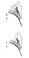
- FIGS. 1 and 2 show in perspective views of and from behind a cultivator tines according to the invention.
- a share carrier 2 is attached on the illustrated lower part of the holding stem 1 .
- a middle share consists of a share tip 3 and a baffle 4, which are formed as separate parts, which, according to the representation, the share tip 3 may be slightly wider than the baffle 4. Both elements are located at the front of the lower end of the stem 1 and Scharness 2 and are fixed there with one screw. A rear flap 5 of the blade tip 3 engages in a corresponding recess of the guide plate 4 and thus forms a positive connection.
- a one-piece wing share 6 is mounted, by means of a quick connection, as will be explained below.
- the middle group 3, 4 is arranged somewhat in front of the wing share 6 and thus leads the way in the operation of the cultivator tine.
- the share tip 3 of the central share 3, 4 is easily replaceable when worn, for which only the relevant one screw must be solved.
- the wing assembly 6, which can be attached and removed frequently, can be mounted, as mentioned, with a quick attachment to the beam carrier 2.
- a quick attachment to the beam carrier 2 Six example embodiments of such a quick fastening are described below with reference to FIGS. 3a to 8a and 8b to 6b.
- the wing share 6 can thus, if the cultivator tines is to be used only with the center flock alone for a deep working of the soil, are easily solved and can be just as fast attached to the cultivator tines for a shallow tillage. If two or more different shapes of wing shares 6 are available for selection, the wing share 6 which is most suitable for the respective application can be attached just as quickly. It is understood that in the drawings, only one embodiment of the wing share to illustrate the invention is shown.
- the coulter support 2 is kept narrow and extends from the cultivator tine 1 only backwards, but overall over its entire extent is significantly narrower than the middle group 3, 4 so that when the cultivator tines without the wing share 6 is used, the coulter holder 2 is not acted upon by the worked ground and thereby wear is avoided.
- FIGS. 3a to 8a show in each case the wing share 6 in a perspective view with the respectively arranged there element of the quick attachment.
- the wing share 6 in each case two relievekantete guide lugs 7, which with the outer surfaces of the two legs of the coulter support 2 (see FIG. 2 ) and center the front end of the wing share 6 respectively on the share carrier 2.
- the FIGS. 4b to 8b each show in side view mounted on the remaining cultivator tines wing share. 6
- FIGS. 3a and 3b shows the quick attachment of the wing share 6 with a arranged on the beam carrier 2 bearing plate 11 with a seated therein screw with nut 12 and a screw hole 13 formed in the wing share 6 so it only needs the nut 12 to be solved to remove the wing share 6 or attach to be able to.
- a modification of this embodiment is the extension of the screw hole 13 in the wing share 6 to a slot running to the rear end. Then it takes to loosen and dismantle the wing share, the nut just to be loosened a bit, then to push the wing share with the screw shaft receiving slot between the nut and contact plate 11 and can pull out.
- the reverse arrangement is also possible, namely a back opening out slot in the contact plate 11th
- FIGS. 4a and 4b show an embodiment in which the share carrier 2, a fixed tab 21 is welded.
- the wing share has in its middle part a suitably sized elongated transverse hole 22, in which the tab 21 engages, and a Wedge 23 with end plate 24 engages from behind under the wing share 6 and passes through an opening in the lower region of the tab 21, wherein the end plate 24 in turn has an opening which receives a rear eyelet 25 of the wing share.
- a safety wedge or fuse element 26 is inserted.
- the connection is made completely gland free.
- FIGS. 5a and 5b shows a quick attachment, where the guide lugs 7 have rearwardly facing slots 31, with which they can be suspended in lateral pins 32 of the coulter 2.
- An eyelet 33 at the rear end of the wing share 6 is inserted through an opening in the rear of the share holder 2 transverse plate 34, and a Sich ceremoniesssplint 35 which is inserted into the eyelet 33, secures the connection, so that the wing share 6 not forward from the Holder can slip out.
- This embodiment is completely without glands.
- FIGS. 6a and 6b shows another screw-free quick release.
- a rearwardly tapered dovetail plate 41 is screwed. Of course it can also be welded on.
- the coulter carrier 2 has a corresponding dovetail receptacle.
- the assembly of the wing share 6 takes place by inserting the plate 41 in the receptacle 42, wherein the fixation is made by self-locking optionally with slight pressure or knocking.
- the taper of the plate 41 and the Au fortune 42 takes place to the rear, ie in the direction of the earth pressure on the wing share 6, so that the working pressure automatically supports the compound.
- the release is done by simply knocking out the wing share 6 forward.
- FIGS. 7a and 7b has instead of a screw, as in the embodiment of the FIGS. 3a and 3b is provided, a bayonet closure 46 which cooperates with the contact plate 45 and the cutout 43 accordingly.
- FIGS. 8a and 8b A modification of the above-described embodiment according to the FIGS. 4a and 4b is in the FIGS. 8a and 8b shown.
- the tab 44 is inserted from below through the wing and the back plate of the blade carrier 2 and also connected to wedge and fuse element. It goes without saying that the tab on the flock can also be firmly connected.
Claims (10)
- Dent de cultivateur, constitué d'un manche (1), d'un support de soc (2) fixé sur celui-ci, d'un soc central (3, 4) et d'un soc à ailettes (6), caractérisé en ce que le soc à ailettes (6) peut être monté au niveau de la face inférieure du support de soc (2) au moyen d'une fixation rapide établissant un assemblage par forme, dans laquelle le soc central (3, 4) et le soc à ailettes (6) sont conçus sous forme de pièces séparées et sont fixés au support de soc (2) de façon à être interchangeables séparément.
- Dent de cultivateur selon la revendication 1, dans laquelle le support de soc ne dépasse pour l'essentiel pas latéralement du manche (1) et présente une largeur inférieure à celle du soc central (3, 4).
- Dent de cultivateur selon la revendication 1 ou 2, dans laquelle le soc à ailettes (6) présente des ergots de guidage (7) au moins au niveau de son extrémité antérieure, lesdits ergots de guidage coopérant avec les faces latérales du support de soc (2).
- Dent de cultivateur selon l'une quelconque des revendications 1 à 3, dans laquelle les ergots de guidage (7) sont formés par des rebords ou similaires au niveau de l'extrémité antérieure du soc à ailettes (6).
- Dent de cultivateur selon l'une quelconque des revendications 1 à 4, dans laquelle la fixation rapide présente une plaque d'appui (11) coopérant avec la face supérieure de la partie centrale du soc à ailettes (6) ou un élément ayant la même fonction ainsi qu'une vis ou fermeture à baïonnette (46) passant à travers un trou de passage (13) ou une fente longitudinale débouchant vers l'arrière du soc à ailettes (6).
- Dent de cultivateur selon l'une quelconque des revendications 1 à 4, dans laquelle la fixation rapide présente une languette (21) disposée sur le support de soc (2) et passant à travers un trou transversal (22) du soc à ailettes (6), ainsi qu'une cale (23) passée à travers une ouverture de la languette (21) et en appui sur la face inférieure du soc à ailettes (6).
- Dent de cultivateur selon l'une quelconque des revendications 1 à 4, dans laquelle la fixation rapide est formée par une languette qui est introduite par le bas à travers un trou du soc à ailettes et du porte soc et qui est assemblée au moyen d'une cale et d'un élément de sécurité.
- Dent de cultivateur selon la revendication 6, dans laquelle la cale (23) est introduite par l'arrière dans l'ouverture de la languette (21) et présente une plaque frontale (24) au niveau de son extrémité arrière, le soc à ailettes (6) étant muni d'un oeillet arrière (25) qui est logé dans une ouverture de la plaque frontale (24) et une cale de sécurité (26) pouvant être passée à travers l'oeillet (25).
- Dent de cultivateur selon l'une quelconque des revendications 1 à 4, dans laquelle la fixation rapide présente des languettes (7) formées au niveau de l'extrémité antérieure du soc à ailettes (6) avec des fentes (31) de type baïonnettes évoluant dans le sens de la longueur et débouchant vers l'arrière, dans lesquelles engrènent des broches ou tenons (32) disposés sur le support de soc (2), et présente un oeillet (33) disposé au niveau de l'extrémité arrière du soc à ailettes (6) qui peut être passé à travers une ouverture d'un contre-élément (34) au niveau du support de soc (2) et peut être bloqué au moyen d'une goupille de sécurité (3 5).
- Dent de cultivateur selon l'une quelconque des revendications 1 à 4, dans laquelle la fixation rapide présente une plaque à queue d'aronde (41) montée au niveau du soc à ailettes (6), qui se rétrécit en forme de cône vers l'arrière, et
présente un logement à queue d'aronde (42) de forme complémentaire à celle-ci, disposé au niveau du support de soc (2).
Applications Claiming Priority (2)
| Application Number | Priority Date | Filing Date | Title |
|---|---|---|---|
| DE10336934 | 2003-08-07 | ||
| DE10336934A DE10336934A1 (de) | 2003-08-07 | 2003-08-07 | Bodengrubber mit Scharschnellwechselsystem |
Publications (2)
| Publication Number | Publication Date |
|---|---|
| EP1504639A1 EP1504639A1 (fr) | 2005-02-09 |
| EP1504639B1 true EP1504639B1 (fr) | 2011-12-28 |
Family
ID=33547190
Family Applications (1)
| Application Number | Title | Priority Date | Filing Date |
|---|---|---|---|
| EP04018455A Not-in-force EP1504639B1 (fr) | 2003-08-07 | 2004-08-04 | Outil d'ameublissement du sol avec système d'échange rapide |
Country Status (3)
| Country | Link |
|---|---|
| EP (1) | EP1504639B1 (fr) |
| AT (1) | ATE538633T1 (fr) |
| DE (1) | DE10336934A1 (fr) |
Cited By (1)
| Publication number | Priority date | Publication date | Assignee | Title |
|---|---|---|---|---|
| DE202014101577U1 (de) | 2014-04-03 | 2014-05-02 | Jens Wiesent | Grubberzinken |
Families Citing this family (7)
| Publication number | Priority date | Publication date | Assignee | Title |
|---|---|---|---|---|
| AT501966B1 (de) | 2005-05-17 | 2007-04-15 | Vogel & Noot Landmaschinen Gmb | Grubberzinken sowie flügelschar hierfür |
| AT501965B1 (de) | 2005-05-17 | 2007-04-15 | Vogel & Noot Landmaschinen Gmb | Grubberzinken sowie scharspitze hierfür |
| DE102009058412B4 (de) * | 2009-12-16 | 2019-02-14 | Landmaschinenfabrik Köckerling GmbH & Co. KG | Bodenbearbeitungsgerätleitblech |
| DE202011107599U1 (de) | 2011-11-08 | 2012-01-12 | Anja Maria Kerner | Grubberzinken mit mittels einer Formschluss-Schnellbefestigung befestigbarer Scharspitze |
| DE102012202799B4 (de) | 2012-02-23 | 2017-12-14 | EuM AGROTEC R.Epple&R.Mürter GbR(vertr.durch die Gesellsch.Hr. R. Epple,73265 Dettingen,Hr. R. Mürter,73108 Gammelshausen) | Landwirtschaftliches bodenbearbeitendes Gerät |
| EP3707979B1 (fr) * | 2015-08-14 | 2022-08-10 | Maximum Soil And Water Productivity Pty Ltd | Ensembles à sillon et d'ameublissement de sol, et rénovateur de lit correspondant |
| RU2600687C1 (ru) * | 2015-09-21 | 2016-10-27 | Федеральное государственное бюджетное научное учреждение Всероссийский научно-исследовательский институт механизации сельского хозяйства (ФГБНУ ВИМ) | Лапа культиватора |
Family Cites Families (11)
| Publication number | Priority date | Publication date | Assignee | Title |
|---|---|---|---|---|
| US1520079A (en) * | 1922-08-24 | 1924-12-23 | Perdue Peter | Hoe for cultivators and seed drills |
| US1650007A (en) * | 1925-06-20 | 1927-11-22 | Harry L Carr | Cultivator tooth |
| US1769545A (en) * | 1929-01-10 | 1930-07-01 | Henry R Pence | Cultivator shovel, weeder, and mulcher |
| US1872623A (en) * | 1932-01-02 | 1932-08-16 | B E G Z Company Inc | Cultivator sweep |
| GB1598453A (en) * | 1977-03-04 | 1981-09-23 | Ransomes Sims & Jefferies Ltd | Tines for stubble cultivation |
| WO1988006398A1 (fr) * | 1987-02-26 | 1988-09-07 | Austin Timothy Ryan | Fixation d'un soc de charrue sur son support |
| US5558165A (en) * | 1995-09-15 | 1996-09-24 | Deere & Company | Agricultural sweep and mounting |
| CA2284457C (fr) * | 1999-10-04 | 2002-12-03 | F.P. Bourgault Tillage Tools Ltd. | Dispositif de retenue de soc a remplacement rapide |
| DE10013621A1 (de) * | 2000-03-18 | 2001-09-20 | Amazonen Werke Dreyer H | Bodenbearbeitungswerkzeug |
| DE10014155A1 (de) * | 2000-03-22 | 2001-09-27 | Lemken Gmbh & Co Kg | Zinken mit Schar und Leitblech |
| US6585058B2 (en) * | 2001-10-19 | 2003-07-01 | Deere & Company | Knock-on sweep structure and tools therefor |
-
2003
- 2003-08-07 DE DE10336934A patent/DE10336934A1/de not_active Withdrawn
-
2004
- 2004-08-04 AT AT04018455T patent/ATE538633T1/de active
- 2004-08-04 EP EP04018455A patent/EP1504639B1/fr not_active Not-in-force
Cited By (2)
| Publication number | Priority date | Publication date | Assignee | Title |
|---|---|---|---|---|
| DE202014101577U1 (de) | 2014-04-03 | 2014-05-02 | Jens Wiesent | Grubberzinken |
| DE102014009577A1 (de) | 2014-04-03 | 2015-10-08 | Kerner Maschinenbau Gmbh | Grubberzinken mit separatem Scharträger |
Also Published As
| Publication number | Publication date |
|---|---|
| ATE538633T1 (de) | 2012-01-15 |
| EP1504639A1 (fr) | 2005-02-09 |
| DE10336934A1 (de) | 2005-03-10 |
Similar Documents
| Publication | Publication Date | Title |
|---|---|---|
| DE3628910C2 (de) | Zinken für Bodenbearbeitungsgeräte mit Flügelschar | |
| EP3753383B1 (fr) | Élément de coupe | |
| DE202014010650U1 (de) | Werkzeug-Werkzeughalter-Einheit, Werkzeughalter und Werkzeug | |
| EP1504639B1 (fr) | Outil d'ameublissement du sol avec système d'échange rapide | |
| DE102016106133B4 (de) | Bodenbearbeitungssystem | |
| EP3818793A1 (fr) | Bande coupante et outil combiné doté d'une bande coupante ainsi que machine de traitement du sol agricole | |
| DE102019106393B4 (de) | Flügelscharspitze und Bodenbearbeitungsgerät damit | |
| DE2926060A1 (de) | Einstellbare verbindung zwischen dem halter eines bodenbearbeitungswerkzeuges und einem fuer wenigstens zwei im abstand angeordnete halter gemeinsamen rahmen | |
| EP1616465A2 (fr) | Outil de travail du sol | |
| DE3439226A1 (de) | Maehgeraet | |
| EP3235358B1 (fr) | Pointe de bande destinée à être utilisée dans un système de soc pour le traitement du sol | |
| DE69608661T3 (de) | Grubberdrillschar | |
| EP3254544B1 (fr) | Appareil de travail du sol | |
| EP1872643B1 (fr) | Dent de sacrificateur doté d'un support de soc | |
| CH713217A1 (de) | Anbaugerät für eine Arbeitsmaschine, insbesodere für einen Bagger. | |
| EP2651205B1 (fr) | Appareil de travail du sol | |
| DE202017106759U1 (de) | Befestigungssystem für eine Bodenbearbeitungsvorrichtung | |
| EP3571905B1 (fr) | Système de soc et pointe de soc destinés à être utilisés dans un système de soc pour le traitement du sol | |
| DE102007029406A1 (de) | Grubberzinken mit separatem Scharträger | |
| DE102014009577A1 (de) | Grubberzinken mit separatem Scharträger | |
| EP0260643A2 (fr) | Couteau pour un cultivateur de gazon | |
| WO2007140874A1 (fr) | Outil agricole à soc pénétrant dans le sol | |
| DE10014155A1 (de) | Zinken mit Schar und Leitblech | |
| EP0170835A1 (fr) | Charrue | |
| EP4356703A1 (fr) | Soc de hachage |
Legal Events
| Date | Code | Title | Description |
|---|---|---|---|
| PUAI | Public reference made under article 153(3) epc to a published international application that has entered the european phase |
Free format text: ORIGINAL CODE: 0009012 |
|
| AK | Designated contracting states |
Kind code of ref document: A1 Designated state(s): AT BE BG CH CY CZ DE DK EE ES FI FR GB GR HU IE IT LI LU MC NL PL PT RO SE SI SK TR |
|
| AX | Request for extension of the european patent |
Extension state: AL HR LT LV MK |
|
| 17P | Request for examination filed |
Effective date: 20050707 |
|
| AKX | Designation fees paid |
Designated state(s): AT BE BG CH CY CZ DE DK EE ES FI FR GB GR HU IE IT LI LU MC NL PL PT RO SE SI SK TR |
|
| 17Q | First examination report despatched |
Effective date: 20080721 |
|
| GRAP | Despatch of communication of intention to grant a patent |
Free format text: ORIGINAL CODE: EPIDOSNIGR1 |
|
| GRAS | Grant fee paid |
Free format text: ORIGINAL CODE: EPIDOSNIGR3 |
|
| GRAA | (expected) grant |
Free format text: ORIGINAL CODE: 0009210 |
|
| RAP1 | Party data changed (applicant data changed or rights of an application transferred) |
Owner name: KERNER, GABRIELE Owner name: KERNER, ANJA MARIA Owner name: KERNER, STEFAN Owner name: KERNER, TOBIAS JOSEF Owner name: KERNER, JUERGEN |
|
| RIN1 | Information on inventor provided before grant (corrected) |
Inventor name: KERNER, JOSEF |
|
| AK | Designated contracting states |
Kind code of ref document: B1 Designated state(s): AT BE BG CH CY CZ DE DK EE ES FI FR GB GR HU IE IT LI LU MC NL PL PT RO SE SI SK TR |
|
| REG | Reference to a national code |
Ref country code: GB Ref legal event code: FG4D Free format text: NOT ENGLISH |
|
| REG | Reference to a national code |
Ref country code: CH Ref legal event code: EP |
|
| REG | Reference to a national code |
Ref country code: AT Ref legal event code: REF Ref document number: 538633 Country of ref document: AT Kind code of ref document: T Effective date: 20120115 |
|
| REG | Reference to a national code |
Ref country code: IE Ref legal event code: FG4D |
|
| REG | Reference to a national code |
Ref country code: DE Ref legal event code: R096 Ref document number: 502004013182 Country of ref document: DE Effective date: 20120308 |
|
| REG | Reference to a national code |
Ref country code: NL Ref legal event code: VDEP Effective date: 20111228 |
|
| PG25 | Lapsed in a contracting state [announced via postgrant information from national office to epo] |
Ref country code: SE Free format text: LAPSE BECAUSE OF FAILURE TO SUBMIT A TRANSLATION OF THE DESCRIPTION OR TO PAY THE FEE WITHIN THE PRESCRIBED TIME-LIMIT Effective date: 20111228 Ref country code: GR Free format text: LAPSE BECAUSE OF FAILURE TO SUBMIT A TRANSLATION OF THE DESCRIPTION OR TO PAY THE FEE WITHIN THE PRESCRIBED TIME-LIMIT Effective date: 20120329 Ref country code: SI Free format text: LAPSE BECAUSE OF FAILURE TO SUBMIT A TRANSLATION OF THE DESCRIPTION OR TO PAY THE FEE WITHIN THE PRESCRIBED TIME-LIMIT Effective date: 20111228 |
|
| PG25 | Lapsed in a contracting state [announced via postgrant information from national office to epo] |
Ref country code: CY Free format text: LAPSE BECAUSE OF FAILURE TO SUBMIT A TRANSLATION OF THE DESCRIPTION OR TO PAY THE FEE WITHIN THE PRESCRIBED TIME-LIMIT Effective date: 20111228 |
|
| REG | Reference to a national code |
Ref country code: IE Ref legal event code: FD4D |
|
| PG25 | Lapsed in a contracting state [announced via postgrant information from national office to epo] |
Ref country code: IE Free format text: LAPSE BECAUSE OF FAILURE TO SUBMIT A TRANSLATION OF THE DESCRIPTION OR TO PAY THE FEE WITHIN THE PRESCRIBED TIME-LIMIT Effective date: 20111228 Ref country code: BG Free format text: LAPSE BECAUSE OF FAILURE TO SUBMIT A TRANSLATION OF THE DESCRIPTION OR TO PAY THE FEE WITHIN THE PRESCRIBED TIME-LIMIT Effective date: 20120328 Ref country code: EE Free format text: LAPSE BECAUSE OF FAILURE TO SUBMIT A TRANSLATION OF THE DESCRIPTION OR TO PAY THE FEE WITHIN THE PRESCRIBED TIME-LIMIT Effective date: 20111228 Ref country code: SK Free format text: LAPSE BECAUSE OF FAILURE TO SUBMIT A TRANSLATION OF THE DESCRIPTION OR TO PAY THE FEE WITHIN THE PRESCRIBED TIME-LIMIT Effective date: 20111228 Ref country code: CZ Free format text: LAPSE BECAUSE OF FAILURE TO SUBMIT A TRANSLATION OF THE DESCRIPTION OR TO PAY THE FEE WITHIN THE PRESCRIBED TIME-LIMIT Effective date: 20111228 Ref country code: NL Free format text: LAPSE BECAUSE OF FAILURE TO SUBMIT A TRANSLATION OF THE DESCRIPTION OR TO PAY THE FEE WITHIN THE PRESCRIBED TIME-LIMIT Effective date: 20111228 |
|
| PG25 | Lapsed in a contracting state [announced via postgrant information from national office to epo] |
Ref country code: PT Free format text: LAPSE BECAUSE OF FAILURE TO SUBMIT A TRANSLATION OF THE DESCRIPTION OR TO PAY THE FEE WITHIN THE PRESCRIBED TIME-LIMIT Effective date: 20120430 Ref country code: PL Free format text: LAPSE BECAUSE OF FAILURE TO SUBMIT A TRANSLATION OF THE DESCRIPTION OR TO PAY THE FEE WITHIN THE PRESCRIBED TIME-LIMIT Effective date: 20111228 Ref country code: RO Free format text: LAPSE BECAUSE OF FAILURE TO SUBMIT A TRANSLATION OF THE DESCRIPTION OR TO PAY THE FEE WITHIN THE PRESCRIBED TIME-LIMIT Effective date: 20111228 |
|
| PLBI | Opposition filed |
Free format text: ORIGINAL CODE: 0009260 |
|
| 26 | Opposition filed |
Opponent name: VOGEL & NOOT LANDMASCHINEN GMBH & CO KG Effective date: 20120914 |
|
| PG25 | Lapsed in a contracting state [announced via postgrant information from national office to epo] |
Ref country code: DK Free format text: LAPSE BECAUSE OF FAILURE TO SUBMIT A TRANSLATION OF THE DESCRIPTION OR TO PAY THE FEE WITHIN THE PRESCRIBED TIME-LIMIT Effective date: 20111228 |
|
| PLAX | Notice of opposition and request to file observation + time limit sent |
Free format text: ORIGINAL CODE: EPIDOSNOBS2 |
|
| PG25 | Lapsed in a contracting state [announced via postgrant information from national office to epo] |
Ref country code: IT Free format text: LAPSE BECAUSE OF FAILURE TO SUBMIT A TRANSLATION OF THE DESCRIPTION OR TO PAY THE FEE WITHIN THE PRESCRIBED TIME-LIMIT Effective date: 20111228 |
|
| REG | Reference to a national code |
Ref country code: DE Ref legal event code: R026 Ref document number: 502004013182 Country of ref document: DE Effective date: 20120914 |
|
| PGFP | Annual fee paid to national office [announced via postgrant information from national office to epo] |
Ref country code: DE Payment date: 20120522 Year of fee payment: 9 Ref country code: FR Payment date: 20120831 Year of fee payment: 9 |
|
| BERE | Be: lapsed |
Owner name: KERNER, TOBIAS JOSEF Effective date: 20120831 Owner name: KERNER, GABRIELE Effective date: 20120831 Owner name: KERNER, STEFAN Effective date: 20120831 Owner name: KERNER, JURGEN Effective date: 20120831 Owner name: KERNER, ANJA MARIA Effective date: 20120831 |
|
| PG25 | Lapsed in a contracting state [announced via postgrant information from national office to epo] |
Ref country code: MC Free format text: LAPSE BECAUSE OF NON-PAYMENT OF DUE FEES Effective date: 20120831 |
|
| PGFP | Annual fee paid to national office [announced via postgrant information from national office to epo] |
Ref country code: AT Payment date: 20120822 Year of fee payment: 9 |
|
| GBPC | Gb: european patent ceased through non-payment of renewal fee |
Effective date: 20120804 |
|
| PLAB | Opposition data, opponent's data or that of the opponent's representative modified |
Free format text: ORIGINAL CODE: 0009299OPPO |
|
| PG25 | Lapsed in a contracting state [announced via postgrant information from national office to epo] |
Ref country code: ES Free format text: LAPSE BECAUSE OF FAILURE TO SUBMIT A TRANSLATION OF THE DESCRIPTION OR TO PAY THE FEE WITHIN THE PRESCRIBED TIME-LIMIT Effective date: 20120408 |
|
| R26 | Opposition filed (corrected) |
Opponent name: VOGEL & NOOT LANDMASCHINEN GMBH & CO KG Effective date: 20120914 |
|
| PG25 | Lapsed in a contracting state [announced via postgrant information from national office to epo] |
Ref country code: BE Free format text: LAPSE BECAUSE OF NON-PAYMENT OF DUE FEES Effective date: 20120831 |
|
| PG25 | Lapsed in a contracting state [announced via postgrant information from national office to epo] |
Ref country code: FI Free format text: LAPSE BECAUSE OF FAILURE TO SUBMIT A TRANSLATION OF THE DESCRIPTION OR TO PAY THE FEE WITHIN THE PRESCRIBED TIME-LIMIT Effective date: 20111228 |
|
| PLBB | Reply of patent proprietor to notice(s) of opposition received |
Free format text: ORIGINAL CODE: EPIDOSNOBS3 |
|
| PG25 | Lapsed in a contracting state [announced via postgrant information from national office to epo] |
Ref country code: GB Free format text: LAPSE BECAUSE OF NON-PAYMENT OF DUE FEES Effective date: 20120804 |
|
| REG | Reference to a national code |
Ref country code: CH Ref legal event code: PL |
|
| REG | Reference to a national code |
Ref country code: AT Ref legal event code: MM01 Ref document number: 538633 Country of ref document: AT Kind code of ref document: T Effective date: 20130804 |
|
| PG25 | Lapsed in a contracting state [announced via postgrant information from national office to epo] |
Ref country code: LI Free format text: LAPSE BECAUSE OF NON-PAYMENT OF DUE FEES Effective date: 20130831 Ref country code: DE Free format text: LAPSE BECAUSE OF NON-PAYMENT OF DUE FEES Effective date: 20140301 Ref country code: CH Free format text: LAPSE BECAUSE OF NON-PAYMENT OF DUE FEES Effective date: 20130831 Ref country code: TR Free format text: LAPSE BECAUSE OF FAILURE TO SUBMIT A TRANSLATION OF THE DESCRIPTION OR TO PAY THE FEE WITHIN THE PRESCRIBED TIME-LIMIT Effective date: 20111228 |
|
| REG | Reference to a national code |
Ref country code: DE Ref legal event code: R119 Ref document number: 502004013182 Country of ref document: DE Effective date: 20140301 |
|
| REG | Reference to a national code |
Ref country code: FR Ref legal event code: ST Effective date: 20140430 |
|
| PG25 | Lapsed in a contracting state [announced via postgrant information from national office to epo] |
Ref country code: AT Free format text: LAPSE BECAUSE OF NON-PAYMENT OF DUE FEES Effective date: 20130804 Ref country code: LU Free format text: LAPSE BECAUSE OF NON-PAYMENT OF DUE FEES Effective date: 20120804 |
|
| PG25 | Lapsed in a contracting state [announced via postgrant information from national office to epo] |
Ref country code: HU Free format text: LAPSE BECAUSE OF FAILURE TO SUBMIT A TRANSLATION OF THE DESCRIPTION OR TO PAY THE FEE WITHIN THE PRESCRIBED TIME-LIMIT Effective date: 20040804 |
|
| PG25 | Lapsed in a contracting state [announced via postgrant information from national office to epo] |
Ref country code: FR Free format text: LAPSE BECAUSE OF NON-PAYMENT OF DUE FEES Effective date: 20130902 |
|
| PLBD | Termination of opposition procedure: decision despatched |
Free format text: ORIGINAL CODE: EPIDOSNOPC1 |
|
| PLBM | Termination of opposition procedure: date of legal effect published |
Free format text: ORIGINAL CODE: 0009276 |
|
| STAA | Information on the status of an ep patent application or granted ep patent |
Free format text: STATUS: OPPOSITION PROCEDURE CLOSED |
|
| 27C | Opposition proceedings terminated |
Effective date: 20150515 |