EP1502099B1 - Vorrichtung und verfahren zur erzeugung einer definierten umgebung für partikelförmige proben - Google Patents
Vorrichtung und verfahren zur erzeugung einer definierten umgebung für partikelförmige proben Download PDFInfo
- Publication number
- EP1502099B1 EP1502099B1 EP03763844A EP03763844A EP1502099B1 EP 1502099 B1 EP1502099 B1 EP 1502099B1 EP 03763844 A EP03763844 A EP 03763844A EP 03763844 A EP03763844 A EP 03763844A EP 1502099 B1 EP1502099 B1 EP 1502099B1
- Authority
- EP
- European Patent Office
- Prior art keywords
- gas
- temperature
- mouth end
- dew
- cooler
- Prior art date
- Legal status (The legal status is an assumption and is not a legal conclusion. Google has not performed a legal analysis and makes no representation as to the accuracy of the status listed.)
- Expired - Lifetime
Links
- 238000000034 method Methods 0.000 title claims description 24
- 230000005494 condensation Effects 0.000 claims abstract description 18
- 238000009833 condensation Methods 0.000 claims abstract description 15
- 239000007789 gas Substances 0.000 claims description 207
- XLYOFNOQVPJJNP-UHFFFAOYSA-N water Chemical compound O XLYOFNOQVPJJNP-UHFFFAOYSA-N 0.000 claims description 32
- 239000007788 liquid Substances 0.000 claims description 23
- 239000012530 fluid Substances 0.000 claims description 17
- 238000001816 cooling Methods 0.000 claims description 11
- 230000008859 change Effects 0.000 claims description 7
- 239000006200 vaporizer Substances 0.000 claims 2
- 239000000523 sample Substances 0.000 description 60
- 239000013078 crystal Substances 0.000 description 34
- 102000004169 proteins and genes Human genes 0.000 description 24
- 108090000623 proteins and genes Proteins 0.000 description 24
- 238000005259 measurement Methods 0.000 description 12
- 238000012360 testing method Methods 0.000 description 12
- 239000000203 mixture Substances 0.000 description 7
- 238000002050 diffraction method Methods 0.000 description 6
- 238000012937 correction Methods 0.000 description 5
- 238000002474 experimental method Methods 0.000 description 5
- 238000005496 tempering Methods 0.000 description 5
- 238000010438 heat treatment Methods 0.000 description 4
- 230000009467 reduction Effects 0.000 description 4
- 238000004458 analytical method Methods 0.000 description 3
- 230000001143 conditioned effect Effects 0.000 description 3
- 230000003750 conditioning effect Effects 0.000 description 3
- 230000001419 dependent effect Effects 0.000 description 3
- 230000007774 longterm Effects 0.000 description 3
- KFZMGEQAYNKOFK-UHFFFAOYSA-N Isopropanol Chemical compound CC(C)O KFZMGEQAYNKOFK-UHFFFAOYSA-N 0.000 description 2
- 230000032683 aging Effects 0.000 description 2
- 230000008014 freezing Effects 0.000 description 2
- 238000007710 freezing Methods 0.000 description 2
- 239000000463 material Substances 0.000 description 2
- 230000035939 shock Effects 0.000 description 2
- XQMVBICWFFHDNN-UHFFFAOYSA-N 5-amino-4-chloro-2-phenylpyridazin-3-one;(2-ethoxy-3,3-dimethyl-2h-1-benzofuran-5-yl) methanesulfonate Chemical compound O=C1C(Cl)=C(N)C=NN1C1=CC=CC=C1.C1=C(OS(C)(=O)=O)C=C2C(C)(C)C(OCC)OC2=C1 XQMVBICWFFHDNN-UHFFFAOYSA-N 0.000 description 1
- 239000004809 Teflon Substances 0.000 description 1
- 229920006362 Teflon® Polymers 0.000 description 1
- 239000000853 adhesive Substances 0.000 description 1
- 230000001070 adhesive effect Effects 0.000 description 1
- 150000001413 amino acids Chemical class 0.000 description 1
- 230000009286 beneficial effect Effects 0.000 description 1
- 230000015572 biosynthetic process Effects 0.000 description 1
- 210000004027 cell Anatomy 0.000 description 1
- 210000003850 cellular structure Anatomy 0.000 description 1
- 150000001875 compounds Chemical class 0.000 description 1
- 238000010276 construction Methods 0.000 description 1
- 230000001276 controlling effect Effects 0.000 description 1
- 239000011549 crystallization solution Substances 0.000 description 1
- 238000013480 data collection Methods 0.000 description 1
- 238000013461 design Methods 0.000 description 1
- 238000011161 development Methods 0.000 description 1
- 230000018109 developmental process Effects 0.000 description 1
- 238000007599 discharging Methods 0.000 description 1
- 230000000694 effects Effects 0.000 description 1
- 230000008020 evaporation Effects 0.000 description 1
- 238000001704 evaporation Methods 0.000 description 1
- 239000011521 glass Substances 0.000 description 1
- 230000006872 improvement Effects 0.000 description 1
- 230000000977 initiatory effect Effects 0.000 description 1
- 238000002156 mixing Methods 0.000 description 1
- 239000012452 mother liquor Substances 0.000 description 1
- 239000011236 particulate material Substances 0.000 description 1
- 230000008569 process Effects 0.000 description 1
- 238000005057 refrigeration Methods 0.000 description 1
- 230000001105 regulatory effect Effects 0.000 description 1
- 229920006395 saturated elastomer Polymers 0.000 description 1
- 150000003384 small molecules Chemical class 0.000 description 1
- 239000000243 solution Substances 0.000 description 1
- 239000002904 solvent Substances 0.000 description 1
- 238000001179 sorption measurement Methods 0.000 description 1
- 229910001220 stainless steel Inorganic materials 0.000 description 1
- 239000010935 stainless steel Substances 0.000 description 1
- 238000012916 structural analysis Methods 0.000 description 1
- 239000000126 substance Substances 0.000 description 1
- 230000005469 synchrotron radiation Effects 0.000 description 1
- 230000009466 transformation Effects 0.000 description 1
- 238000004804 winding Methods 0.000 description 1
Images

Classifications
-
- G—PHYSICS
- G01—MEASURING; TESTING
- G01N—INVESTIGATING OR ANALYSING MATERIALS BY DETERMINING THEIR CHEMICAL OR PHYSICAL PROPERTIES
- G01N23/00—Investigating or analysing materials by the use of wave or particle radiation, e.g. X-rays or neutrons, not covered by groups G01N3/00 – G01N17/00, G01N21/00 or G01N22/00
- G01N23/20—Investigating or analysing materials by the use of wave or particle radiation, e.g. X-rays or neutrons, not covered by groups G01N3/00 – G01N17/00, G01N21/00 or G01N22/00 by using diffraction of the radiation by the materials, e.g. for investigating crystal structure; by using scattering of the radiation by the materials, e.g. for investigating non-crystalline materials; by using reflection of the radiation by the materials
- G01N23/20008—Constructional details of analysers, e.g. characterised by X-ray source, detector or optical system; Accessories therefor; Preparing specimens therefor
- G01N23/20025—Sample holders or supports therefor
-
- G—PHYSICS
- G01—MEASURING; TESTING
- G01N—INVESTIGATING OR ANALYSING MATERIALS BY DETERMINING THEIR CHEMICAL OR PHYSICAL PROPERTIES
- G01N23/00—Investigating or analysing materials by the use of wave or particle radiation, e.g. X-rays or neutrons, not covered by groups G01N3/00 – G01N17/00, G01N21/00 or G01N22/00
- G01N23/20—Investigating or analysing materials by the use of wave or particle radiation, e.g. X-rays or neutrons, not covered by groups G01N3/00 – G01N17/00, G01N21/00 or G01N22/00 by using diffraction of the radiation by the materials, e.g. for investigating crystal structure; by using scattering of the radiation by the materials, e.g. for investigating non-crystalline materials; by using reflection of the radiation by the materials
-
- G—PHYSICS
- G01—MEASURING; TESTING
- G01N—INVESTIGATING OR ANALYSING MATERIALS BY DETERMINING THEIR CHEMICAL OR PHYSICAL PROPERTIES
- G01N1/00—Sampling; Preparing specimens for investigation
- G01N1/02—Devices for withdrawing samples
- G01N1/22—Devices for withdrawing samples in the gaseous state
Definitions
- the present invention relates to devices and method for creating a defined environment for particulate samples and especially for particulate Samples kept in an environment of defined humidity must be such.
- Protein crystallography is a procedure for Structural analysis of proteins in which these in one crystallized state of an X-ray or Synchrotron radiation to be exposed to Diffraction images to elucidate the molecular structure.
- Attachment of irregularly shaped proteins in one Protein crystal arise channels, which with Crystallization solution are filled. Protein crystals are by the high solvency content as well as by the comparison very weak contacts to crystals of small molecules sensitive and stable only in a special environment.
- Such systems are for example in Reiner Kiefersauer et al., "Free-mounting system for protein crystals: transformation and improvement of diffraction power by accurately controlling humidity changes ", J. Appl. Cryst. (2000), 33, p. 1.223 - 1.230, and EP-A-0987543 known.
- These known systems comprise a measuring head, the both a holder for a to be examined Protein crystal as well as a gas channel for supplying a wet air flow to the protein crystal.
- the Humidity of the air flow is in these known systems set using a humidity control system, depending on the detected by means of a humidity sensor Moisten the mixing ratio of a dry air flow and a wet air flow, thus the humidity to regulate the air flow.
- the Humidity of the gas by changing the temperature of the Liquid or by changing the composition the same can be manipulated.
- the gas with the sun Humidity is set via a buffer vessel Nozzle supplied, at the outlet end of a holder Crystal is arranged so that a laminar gas flow on meets the crystal.
- the known systems for adjusting the humidity of a Gas flow are disadvantageous in that with the same an exact adjustment of the humidity, especially in one area of interest just below 100% relative Moist, difficult to realize.
- the former Procedure is using a humidity sensor due to the spatial narrowness of the crystal the use of the Sensors for measuring the relative humidity directly at the measuring location not possible to control a humidifier.
- available on the market relative humidity sensors not sufficient accuracy and Long-term stability in the required humidity range.
- the object of the present invention is Devices and methods for generating a defined Environment for particulate samples to create a high-precision and long-term stable moisture conditioning on Allow location of a particulate sample.
- a high required accuracy the humidity values of a test gas typically air, at To reach a particle-like sample on one Regulation of the humidity by means of a control circuit Humidification and humidity sensor omitted.
- the adjustment of the moisture is carried out according to the invention the specification of the dew point temperature without active Humidity measurement. It is according to the invention for Moisture setting of the dew point a two-stage Used conditioning, using a Humidification unit and a condensation unit in the Form of a recooler takes place. In the humidification unit If the test gas is provided with too high a humidity, by both the dew point and temperature of the test gas set a value above the desired value become.
- the gas in the recooler again cooled, leaving excess water in the gas again condensed.
- the recooler temperature, on the the gas is cooled, the desired gas dew point.
- the dew point temperature corresponds to the gas temperature, at which is just 100% relative humidity in the gas, d. H. the gas is completely saturated, even minimal additional amounts of water can no longer be removed from the gas be recorded. This condition is caused by the achieved controlled condensation.
- the thus conditioned test gas typically air, becomes led to the measuring head and takes in the local heat exchanger desired gas temperature.
- a condensation of To prevent moisture from the same be in the Usually heated lines, the test gas above the Keep cooler temperature, used.
- the temperature of the Gas at the mouth end is controlled, so that the Moisture content of the sample gas, expressed in relative terms Humidity, clearly by calculation from the sizes "Dew point temperature” and "gas temperature at the end of the muzzle” results. Changes in the moisture content can now adjusted by either the dew point temperature, d. H. the radiator temperature, or the gas temperature at Muzzle end be adjusted accordingly.
- the setting of the test gas temperature at the mouth end takes place preferably by adjusting the Temperature of a measuring head through which the test gas is passed and that has the mouth end.
- the temperature of the Measuring head can by means of any known devices be set, for example, using Heating windings, using Peltier elements or using a liquid heat exchanger.
- a heating of the test gas in the measuring head is through the Use of refrigeration units so that a cooling possible, so that a further temperature range of the Test gas can be adjusted. By a cooling is it also possible, very high depending on the outside temperature To set damp.
- the temperature is preferably on Probe and thus the gas temperature to a constant Value controlled or regulated while the Dew point temperature, i. the cooler temperature, is varied according to the desired humidity.
- the dew point temperature can be kept constant and the temperature of the probe head according to the desired humidity can be varied.
- the preferably arranged directly at the mouth end is to increase, include preferred embodiments the present invention, a device to the flow-dependent pressure loss in the gas line between the radiator and the muzzle at the setting of relative humidity, d. H. the setting of the gas dew point or the setting of the gas temperature at the mouth end, too compensate.
- the Device according to the invention further in addition to Conditioning of temperature and humidity of the test gas the admixing of one or more additional foreign gases and / or one with an evaporator in a gaseous Condition transferred liquid.
- the Device corresponding mass flow controller to all Fluid flows, d. H. Measuring gas, foreign gases and / or liquid, to dose, so that from the ratio of the Mass flows a reduction or increase in the recooler set dew point or the gas temperature on Muzzle end can be calculated.
- mass flow controllers can also others Means for generating a defined flow or Volume flow can be used, for example Facilities powered by a stepper motor Pumps to thereby define a defined To cause flow.
- the accuracy of the humidity setting is not of Humidity sensors, but only of long-term stability Temperature sensors used for setting gas temperature at Muzzle end and to adjust the cooler temperature used, these temperature sensors are not must come into direct contact with the test gas. Consequently occur according to the invention, the disadvantages of relative humidity sensors not that consist in that in such Sensors an aging of the sensor material the characteristic shifts that such sensors have poor accuracy ranging from 90% relative humidity to 100% relative Have moisture that said aging in this Area is even more extreme, and that moisture sensors with a reasonable accuracy are extremely expensive. moreover have cheaper sensors usually only one limited measuring range. Enable dew point sensor Furthermore, not a dew point constancy in the range of hundredths of a degree while using this Temperature sensors, as carried out according to the invention, can be guaranteed.
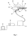
- Fig. 1 shows a system in which the present invention Application can find that a control computer 10, a Control electronics 12, a humidifying unit 14 and a Sample head 16 has.
- the probe head 16 may be a conventional probe head, as described, for example, in the abovementioned EP-A-0987543 is described.
- This probe head comprises an outer part 18 and an inner part 20, preferably with respect to Outer part 18 is movable. Attached to the inner part 20 is a holding element 22 for holding a particulate Sample, in particular a protein crystal.
- a particulate Sample in particular a protein crystal.
- invention is not to be used for particulate samples in the form of protein crystals limited but can be beneficial for any particulate samples are used which have a high Have liquid content, i. in a damp Environment must be kept.
- biological Objects such as B. biological cells or Cell components, or synthetic non-crystalline ones Objects with a high solvent content.
- the holding member 22 as a Loop holder shown as a support end a Loop (loop) possesses, into which a protein crystal can be used.
- loop holders are from the protein crystallography in particular to Shock freezing of samples known.
- the Holder a vacuum operated hollow capillary (Vacuum tweezers) or even a compact, elongated, have tip-shaped component, at the end of a Support for the particulate material sample is given.
- the device according to the invention are any Mounting devices applicable in which the particulate sample at the support end of a holding element under the influence of adsorption forces, electrical forces, an adhesive material or the like can adhere.
- the probe head 16 further includes a gas duct 24 through which a humid air flow to the Support end of the retaining element 22 and thus the Particulate sample can be supplied.
- a gas duct 24 To the Gas duct 24 is connected to a gas line 28, via the the probe head 16 is connected to the moistening unit 14 is.
- the moist gas stream 26 is thereby under pressure from the Humidifying unit 14 via the gas line 28 and the Gas duct 24 to a mouth end 30 of the gas channel 24th directed.
- the support end of the retaining element 22 is located preferably immediately at the mouth end 30, but with a certain spacing, for example in the Order of magnitude of 1 to 10 mm, preferably 2 to 3 mm, in The rule is provided for a simultaneous analysis of the Crystal state using an X-ray camera too enable.
- the gas channel 24 and the Muzzle end 30 of the same designed to be in the area of Supporting the retaining element 22 a substantially to ensure laminar gas flow 26.
- the flow rate of the humid Air flow 26 is adjusted to prevent the generation of a laminar flow in the region of the support end of the Support member 22 to support, with a useful Flow rate in the range of 0.6 to 2.0 1 / min can be.
- the probe head 16 further comprises a tempering device 32 to adjust the temperature T P thereof.
- the gas channel 24 through the probe head 16 is designed such that the humid air flow takes the temperature Tp of the probe head 16 when it flows through the probe head.
- the gas channel 24 may have a corresponding course or may, for example, be designed as a plurality of sub-channels.
- a temperature sensor (not shown) is further provided on the same in a known manner.
- the tempering device 32 may be any known Be means for adjusting the temperature.
- Invention is the tempering 32 a Liquid heat exchanger for sample head temperature control, the both heating and cooling the probe head 16 allows.
- conventional Peltier elements or Heating elements for setting the sample head temperature and thus the humidifier flowing through the sample head Air flow can be used.
- gas line 28 is shown while other compounds, such as electrical Connecting lines, lines for supplying a Temperierfluids, lines for supplying a vacuum for a holding capillary and the like, not shown.
- the present invention is not directed to a probe head, which combines a holding element and a gas supply has limited. Rather, a holding element and separate from it a device containing a wet gas stream directed to the holding element, be provided.
- a device containing a wet gas stream directed to the holding element be provided.
- Such Device may, for example, an elongated nozzle of a have sufficient length to produce a to support laminar gas flow.
- control electronics 12 to the commands of the Control computer 10 of the humidifying unit 14 and the Supply probe 16. After neither the control computer 10 nor the control electronics 12 subject of the present Invention, they require no further herein Explanation.
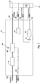
- a device for generating a defined environment for particulate samples shown schematically in Fig. 2 is explained in more detail.
- This comprises a fluid module 34, which is connected to the probe head 16 via a plurality of fluid lines 36, 38, 40 and 42.
- the measuring gas is supplied to the sample head via the fluid line 36 and provided at the mouth end 30 thereof.
- the gas which is fed to the location of the particulate sample, ie substantially the mouth end, in order to set the desired relative humidity is referred to as the measurement gas.
- the measurement gas assumes the temperature T p of the probe head 16.
- the humidifying unit for generating by the Fluid line 36 guided humid gas flow includes a Humidifier 44 and a recooler 46.
- the recooler 46 has a temperature control device 48 for adjustment the radiator temperature of the chiller 46.
- the input of the Humidifier 44 is connected to a compressed air line 50, while the output of the same with the input of the Rear cooler 46 is connected.
- the output of the recooler 46 is connected to the fluid line 36.
- the recooler 46 also has an output with a Condensate line 52 is connected.
- the fluid line 38 is connected to a vacuum pump 54 and further with a holding capillary provided in the sample head 16 (not shown) to form a particulate sample on the Supporting the holding capillary to hold.
- the two fluid lines 40 and 42 provide lines to Feeding and discharging a tempering fluid for adjustment the temperature of the probe head 16.
- these fluid lines in a known form with a Temperature control 56 and a pump 58 for Supplying a Temperierfluidhnes through the Temperierfluid Oberen 40 and 42 connected.
- Fig. 2 is a Gas flow defined moisture at the mouth end 30 as follows generated.
- the radiator temperature is adjusted to thereby set the desired humidity at the location of the sample.
- the humidifier 44 is first supplied with compressed air via the line 50, which is exposed to excess moisture in the humidifier 44, ie a dew point and a temperature above the desired value.
- This too moist gas is fed to the recooler 46 and cooled to the cooler temperature T K.
- excess water is condensed in the gas, so that the cooler temperature T K sets the desired gas dew point and thus the dew point temperature T dp of the sample gas.
- the condensate produced is discharged via the line 52.
- the measurement gas with the desired dew point temperature T dp is passed under pressure via the fluid line 36 to the mouth 30 in the manner described above. It must be ensured that no condensation takes place between the recooler and the measuring head 16, so that no reduction of the dew point temperature can take place.
- the gas line 36 is preferably formed by a heated gas line, for example a flexible heated Teflon line. If it is ensured that the radiator temperature T K is always below the ambient temperature in which the system is operated, the provision of a heater for the fluid line 36 is not required, since then it is ensured without providing a heater that the temperature of the measurement gas after leaving of the recooler does not fall below the radiator temperature and thus condensation does not take place.
- the dew point temperature ie the temperature at which the relative humidity at a given pressure is 100%
- the dew point temperature can be set exactly. After the recooler, any further condensation of moisture from the sample gas is prevented.
- the relative humidity at the mouth end 30 and thus on the crystal according to the above-mentioned Magnus formula depends only on the dew point temperature of the measurement gas and the temperature of the measurement gas at the mouth end 30.
- the sample head 16 is controlled using the tempering to a given temperature T P , so that the relative humidity of the Meßgasstroms can be changed by adjusting the dew point temperature of the measurement gas.
- This dew point temperature of the measurement gas corresponds to the radiator temperature T K , so that by adjusting the radiator temperature, the relative humidity of the measurement gas at the mouth end 30 can be adjusted.
- Embodiments provided a correction device, to pressure differences between the mouth end and the Recooler to consider.
- the pressure difference between the pressure in the recooler and the pressure at the mouth end must be determined.
- a typical ambient pressure p P of 980 mbar can be assumed for simplicity.
- an absolute pressure sensor may be provided on the probe head to detect the exact ambient pressure.
- the pressure P K present in the recooler 46 is detected by means of a pressure sensor, preferably a differential pressure sensor. The actual pressure in the recooler p K varies depending on the set gas flow and temperature.
- the associated dew point temperature T dp is now determined from the desired relative humidity and the given sample head temperature via the above Magnum formula. From this dew point temperature, the associated water vapor partial pressure e P is calculated via the vapor pressure curve. This can be calculated directly by the control computer or determined by accessing a lookup table.
- e K e P ⁇ P K P P ,
- this water vapor partial pressure e K can in turn be converted into a dew point temperature to be set on the recooler.
- the re-cooler temperature T K is set in order to obtain the desired moisture at the location of the sample.
- Preferred embodiments of the present invention allow the addition of foreign gases and / or Liquids in the sample gas stream.
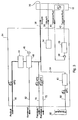
- modified Fluid module 64 is shown in FIG.
- Foreign gas lines 70 and 72 via respective mass flow controller MFC connected to the sample gas line 36.
- About these Lines 70 and 72 may be a foreign gas 1 and a foreign gas 2 are introduced into the measuring gas.
- a liquid 80 may be via a liquid line 68, in which a mass flow controller MFC is provided, a Direct evaporator 82 are supplied, which via a Gas line 84 is connected to the sample gas line 36.
- a mass flow controller MFC MFC
- a Direct evaporator 82 are supplied, which via a Gas line 84 is connected to the sample gas line 36.
- the Direct evaporator causes a residue-free evaporation the liquid supplied to it, so that the mass flow of liquid supplied to it the gas leaving it equivalent.
- both the measuring gas and the foreign gases 1 and 2 and the Liquid can be metered via mass flow regulator can the ratio formation of the mass flows a reduction or Raising the dew point set in the recooler be calculated so that these in the setting of Humidity of the measuring gas at the mouth end 30 taken into account can be.
- the supplied liquid 80 may an anhydrous liquid, for example Isopropanol, act. If the liquid is not anhydrous, This must also be done when setting the humidity be taken into account.
- the present invention thus allows any Metering of foreign gases or liquids via a internal evaporator to the sample gas, the dosage All fluids through the mass flow controller MFC takes place, so that the respective metering in the adjustment of the humidity by a corresponding reduction or increase in the Recooler set dew point are taken into account can.
- the humidifier used according to the invention Supplying the gas with an increased humidity and an elevated temperature before the same one Can be subjected to re-cooling, a conventional Bubble column (bubbler).
- a design of such a humidifier is shown in FIG. 4.
- the humidifier is here as a Circulating humidifier realized that a humidifier unit 90, the one input, which is connected to the Preß Kunststofftechnisch 50 is, and an output connected to an input of a Separator 92 is connected.
- the output of the Separator 92 is connected to the recooler 46.
- the Trap 92 is also connected via a line 94 with a Water supply 96 connected.
- the pump 98 of the humidifier unit 90 water from the water supply 96 supplied, wherein the measurement gas, d. H. the compressed air, in the Humidifier 90 is moistened with the water.
- liquid Water is deposited in the separator 92 and over the Line 94 returned to the water supply 96.
- One Circulating humidifier, as shown in Fig. 4 is compared to an unwieldy bubble column advantageous because he can be made more compact.
- the inventive device and the invention Methods allow a highly accurate setting of Moist over a large area and especially one Highly accurate humidity setting in the for a Protein crystallography area of interest scarce below 100% relative humidity, for example between 80% and 100% relative humidity. You can do that According to the invention particulate samples at any Temperatures examine, with only the appropriate Gas temperature over the sample head temperature Tp accordingly must be set. Depending on the temperature of the Probe head can adjust the dew point temperature corresponding regulation of the temperature of the recooler be adjusted to obtain a desired humidity. Peltier elements can advantageously be used for this purpose which are an increased stability of the temperature control enable.
- the device according to the invention is particularly suitable for use in the field of protein crystallography. It is known that by crystal shrinkage the Improves crystal order in protein crystals, this process being directly related to the water content in the Crystal can be controlled. As stated above, This water content can be controlled by the present invention be controlled exactly.
- the Control computer 10 and the control electronics 12 designed, to perform predetermined humidity experiments. It can the device according to the invention preferably means which allow various parameters, such as Starting moisture, final humidity and humidity gradient, targeted. Furthermore, the present invention Have facilities that allow it during such humidity experiments the change of the crystalline To follow order in the X-ray.
- An exemplary humidity experiment by the inventive device for generating a defined environment for particulate samples can be performed, for example, is first to a protein crystal in its native state assemble and then characterize the Crystal system to go through a damp lamp.
- Start humidity can be the relative humidity of the native State can be selected while as the final moisture Moisture value is used, the starting moisture minus 20% equivalent.
- the change of humidity can be, for example, in 0.25% steps, so that at a Humidity difference of 20% yield eighty humidity levels.
- Time spent on a particular level can be a time of 30 seconds are implemented so that the total duration such a humidity experiment would be 50 minutes.
- the reaction of the crystal to the change in humidity can be recorded continuously with x-rays.
Landscapes
- Chemical & Material Sciences (AREA)
- Crystallography & Structural Chemistry (AREA)
- Physics & Mathematics (AREA)
- Health & Medical Sciences (AREA)
- Life Sciences & Earth Sciences (AREA)
- Analytical Chemistry (AREA)
- Biochemistry (AREA)
- General Health & Medical Sciences (AREA)
- General Physics & Mathematics (AREA)
- Immunology (AREA)
- Pathology (AREA)
- Sampling And Sample Adjustment (AREA)
- Analysing Materials By The Use Of Radiation (AREA)
- Peptides Or Proteins (AREA)
Description
- eine Einrichtung zum Bereitstellen eines Gases, das eine erste Temperatur und eine erste relative Feuchte aufweist, so daß das Gas eine erste Taupunkttemperatur besitzt;
- einen Kühler zum Abkühlen des Gases auf eine Kühlertemperatur unter Kondensation von Feuchtigkeit, um eine zweite Taupunkttemperatur des Gases, die der Kühlertemperatur entspricht, einzustellen;
- eine Einrichtung zum Leiten des Gases mit der zweiten Taupunkttemperatur zu dem Mündungsende unter Verhinderung einer Kondensation von Feuchtigkeit aus dem Gas; und
- eine Einrichtung zum Einstellen der Kühlertemperatur und der Temperatur des Gases an dem Mündungsende zum Einstellen der relativen Feuchte des Gases an dem Mündungsende.

- Fig. 1
- eine schematische Darstellung eines Systems, bei dem eine erfindungsgemäße Vorrichtung verwendet werden kann;
- Fig. 2
- eine schematische Darstellung eines Ausführungsbeispiels einer erfindungsgemäßen Vorrichtung;
- Fig. 3
- eine schematische Darstellung eines alternativen Ausführungsbeispiels einer erfindungsgemäßen Vorrichtung; und
- Fig. 4
- eine schematische Darstellung eines weiteren alternativen Ausführungsbeispiels einer erfindungsgemäßen Vorrichtung.
Claims (24)
- Vorrichtung zur Erzeugung einer definierten Umgebung für partikelförmige Proben mit folgenden Merkmalen:wobei die Vorrichtung zum Erzeugen des feuchten Gasstroms folgende Merkmale aufweist:einem Halteelement (22) mit einem Auflageende für eine partikelförmige Probe;einer Vorrichtung zum Erzeugen eines feuchten Gasstroms an einem Mündungsende (30) derselben, wobei das Mündungsende (30) auf das Auflageende gerichtet ist,eine Einrichtung (44; 90 - 98) zum Bereitstellen eines Gases, das eine erste Temperatur und eine erste relative Feuchte aufweist, so daß das Gas eine erste Taupunkttemperatur besitzt;einen Kühler (46) zum Abkühlen des Gases auf eine Kühlertemperatur unter Kondensation von Feuchtigkeit, um eine zweite Taupunkttemperatur des Gases, die der Kühlertemperatur entspricht, einzustellen;eine Einrichtung (24, 28; 36) zum Leiten des Gases mit der zweiten Taupunkttemperatur zu dem Mündungsende (30) unter Verhinderung einer Kondensation von Feuchtigkeit aus dem Gas; undeine Einrichtung zum Einstellen der relativen Feuchte des Gases an dem Mündungsende (30) durch Einstellen der Kühlertemperatur und Einstellen der Temperatur des Gases an dem Mündungsende.
- Vorrichtung gemäß Anspruch 1, bei der die Einrichtung zum Leiten des Gases eine Fluidleitung (28) und einen Meßkopf (16), der das Mündungsende (30) aufweist, aufweist, wobei ferner Einrichtungen zum Halten der Temperatur der Fluidleitung (28; 36) und des Meßkopfes 16) auf einer Temperatur, die die zweite Taupunkttemperatur nicht unterschreitet, vorgesehen sind.
- Vorrichtung gemäß Anspruch 1 oder 2, die eine Einrichtung (10) zum Ermitteln einer einzustellenden zweiten Taupunkttemperatur auf der Grundlage einer gewünschten relativen Feuchte des Gases an dem Mündungsende (30) und einer Temperatur, auf die das Gas an dem Mündungsende (30) eingestellt wird, aufweist.
- Vorrichtung gemäß Anspruch 3, bei der die Einrichtung zum Einstellen der Temperatur die Kühlertemperatur auf die ermittelte zweite Taupunkttemperatur einstellt und die Temperatur des Gases am Mündungsende (30) auf einen konstanten Wert einstellt.
- Vorrichtung gemäß Anspruch 1 oder 2, die ferner eine Einrichtung zur Berücksichtigung eines Druckunterschieds zwischen einem Druck im Kühler (46) und einem Druck am Mündungsende (30) beim Einstellen der relativen Feuchte am Mündungsende (30) aufweist.
- Vorrichtung gemäß Anspruch 5, die ferner eine Einrichtung zum Ermitteln des Druckunterschieds basierend auf einem erfaßten Druck in dem Kühler (46) und einem erfaßten Absolutdruck am Mündungsende (30) oder basierend auf einem erfassten Druck in dem Kühler (46) und einem typischen Umgebungsdruck aufweist.
- Vorrichtung gemäß Anspruch 6, die ferner eine Einrichtung zum Ermitteln einer einzustellenden zweiten Taupunkttemperatur auf der Grundlage einer gewünschten relativen Feuchte des Gases an dem Mündungsende (30) und einer Temperatur, auf die das Gas an dem Mündungsende (30) eingestellt wird, aufweist, die folgende Merkmale aufweist:eine Einrichtung zum Ermitteln einer an dem Mündungsende erforderlichen Taupunkttemperatur des Gases auf der Grundlage der gewünschten relativen Feuchte und der Temperatur des Gases am Mündungsende (30);eine Einrichtung zum Ermitteln eines erforderlichen Wasserdampfpartialdrucks des Gases am Mündungsende (30) aus der Temperatur des Gases am Mündungsende (30) und der erforderlichen Taupunkttemperatur des Gases am Mündungsende;eine Einrichtung zum Ermitteln eines im Kühler (46) erforderlichen Wasserdampfpartialdruckes basierend auf dem erforderlichen Wasserdampfpartialdruck des Gases am Mündungsende (30) und dem Druckunterschied; undeine Einrichtung zum Ermitteln der einzustellenenden zweiten Taupunkttemperatur des Gases basierend auf dem ermittelten erforderlichen Wasserpartialdruck im Kühler (46).
- Vorrichtung gemäß einem der Ansprüche 1 bis 7, bei der die Einrichtung (48) zum Einstellen der Kühlertemperatur und der Temperatur des Gases am Mündungsende (30) ausgebildet ist, um die Temperaturen derart einzustellen, daß vorbestimmte Verläufe der Feuchte des Gasstroms eingestellt werden.
- Vorrichtung gemäß einem der Ansprüche 1 bis 8, die ferner eine Einrichtung (70, 72, MFC) zum Zuführen eines oder mehrerer Fremdgase in den feuchten Gasstrom aufweist.
- Vorrichtung gemäß einem der Ansprüche 1 bis 9, die ferner einen Direktverdampfer (82) zum Zuführen einer verdampften Flüssigkeit zu dem feuchten Gasstrom aufweist.
- Vorrichtung gemäß Anspruch 8 oder 9, die ferner eine Einrichtung zum Berücksichtigen der Änderung des Taupunkts des feuchten Gasstroms durch das Zuführen des einen oder der mehreren Fremdgase und/oder das Zuführen der verdampften Flüssigkeit beim Einstellen der relativen Feuchte am Mündungsende (30) aufweist.
- Vorrichtung gemäß einem der Ansprüche 1 bis 11, bei der die Einrichtung zum Einstellen der Temperatur am Mündungsende (30) eine Einrichtung zum Einstellen der Temperatur eines Probenkopfs (16), der das Mündungsende (30) aufweist, aufweist.
- Verfahren zur Erzeugung einer definierten Umgebung für partikelförmige Proben mit folgenden Schritten:Halten einer partikelförmigen Probe an einem Auflageende eines Halteelements (22);Erzeugen eines feuchten Gasstroms (26) an einem Mündungsende (30), das auf das Auflageende gerichtet ist, mit folgenden Teilschritten:Bereitstellen eines Gases, das eine erste Temperatur und eine erste relative Feuchte aufweist, so daß das Gas eine erste Taupunkttemperatur besitzt;Abkühlen des Gases auf eine Kühlertemperatur unter Kondensation von Feuchtigkeit, um eine zweite Taupunkttemperatur des Gases, die der Kühlertemperatur entspricht, einzustellen;Leiten des Gases mit der zweiten Taupunkttemperatur zu dem Mündungsende (30), wobei verhindert wird, daß Feuchtigkeit aus dem Gas kondensiert; undEinstellen der Kühlertemperatur und der Temperatur des Gases an dem Mündungsende (30) zum Einstellen der relativen Feuchte des Gases an dem Mündungsende.
- Verfahren gemäß Anspruch 13, das ferner den Schritt des Haltens des Gases mit der zweiten Taupunkttemperatur nach dem Abkühlen desselben auf die Kühlertemperatur auf einer Temperatur, die die zweite Taupunkttemperatur nicht unterschreitet, aufweist.
- Verfahren gemäß Anspruch 13 oder 14, das ferner einen Schritt des Ermittelns einer einzustellenden zweiten Taupunkttemperatur auf der Grundlage einer gewünschten relativen Feuchte des Gases an dem Mündungsende (30) und einer Temperatur, auf die das Gas an dem Mündungsende (30) eingestellt wird, aufweist.
- Verfahren gemäß Anspruch 15, bei dem beim Schritt des Einstellens der Temperatur die Kühlertemperatur auf die ermittelte zweite Taupunkttemperatur eingestellt wird und die Temperatur des Gases am Mündungsende (30) auf einen konstanten Wert eingestellt wird.
- Verfahren gemäß Anspruch 11 oder 12, das ferner einen Schritt des Berücksichtigens eines Druckunterschieds zwischen einem Druck, der beim Kühlen des Gases auf die Kühlertemperatur vorliegt, und einem Druck am Mündungsende (30) beim Einstellen der relativen Feuchte aufweist.
- Verfahren gemäß Anspruch 17, bei dem der Schritt des Berücksichtigens eines Druckunterschieds einen Schritt des Ermittelns des Druckunterschieds basierend auf einem erfaßten Druck in einem Kühler (46), in dem das Gas auf die zweite Taupunkttemperatur gekühlt wird, und einem erfaßten Absolutdruck am Mündungsende (30) oder basierend auf dem erfassten Druck in dem Kühler (46) und einem typischen Umgebungsdruck aufweist.
- Verfahren gemäß Anspruch 18, das ferner einen Schritt des Ermittelns einer einzustellenden zweiten Taupunkttemperatur auf der Grundlage einer gewünschten relativen Feuchte des Gases an dem Mündungsende (30) und einer Temperatur, auf die das Gas an dem Mündungsende (30) eingestellt wird, aufweist, der folgende Teilschritte umfaßt:Ermitteln einer an dem Mündungsende erforderlichen Taupunkttemperatur des Gases auf der Grundlage der gewünschten relativen Feuchte und der Temperatur des Gases am Mündungsende (30);Ermitteln eines erforderlichen Wasserdampfpartialdrucks des Gases am Mündungsende (30) aus der Temperatur des Gases am Mündungsende (30) und der erforderlichen Taupunkttemperatur des Gases am Mündungsende;Ermitteln eines im Kühler (46) erforderlichen Wasserdampfpartialdruckes basierend auf dem erforderlichen Wasserdampfpartialdruck des Gases am Mündungsende (30) und dem Druckunterschied; undErmitteln der einzustellenden zweiten Taupunkttemperatur des Gases basierend auf dem ermittelten erforderlichen Wasserpartialdruck im Kühler (46).
- Verfahren gemäß einem der Ansprüche 13 bis 19, bei dem im Schritt des Einstellens der Kühlertemperatur und der Temperatur des Gases am Mündungsende (30) dieselben derart eingestellt werden, daß vorbestimmte Verläufe der Feuchte des Gasstroms (26) eingestellt werden.
- Verfahren gemäß einem der Ansprüche 13 bis 20, das ferner einen Schritt des Zuführens eines oder mehrerer Fremdgase zu dem feuchten Gasstrom (26) aufweist.
- Verfahren gemäß einem der Ansprüche 13 bis 21, das ferner einen Schritt des Zuführens einer mittels eines Direktverdampfers verdampften Flüssigkeit zu dem feuchten Gasstrom aufweist.
- Verfahren gemäß Anspruch 21 oder 22, das ferner einen Schritt des Berücksichtigens der Änderung des Taupunkts des feuchten Gasstroms durch das Zuführen des einen oder der mehreren Fremdgase und/oder das Zuführen der verdampften Flüssigkeit beim Einstellen der relativen Feuchte des Gases am Mündungsende aufweist.
- Verfahren gemäß einem der Ansprüche 13 bis 23, bei dem der Schritt des Einstellens der Gastemperatur am Mündungsende einen Schritt des Einstellens der Temperatur eines Probenkopfs (16), der das Mündungsende (30) aufweist, aufweist.
Applications Claiming Priority (3)
| Application Number | Priority Date | Filing Date | Title |
|---|---|---|---|
| DE10232172A DE10232172B4 (de) | 2002-07-16 | 2002-07-16 | Vorrichtung und Verfahren zur Erzeugung einer definierten Umgebung für partikelförmige Proben |
| DE10232172 | 2002-07-16 | ||
| PCT/EP2003/007606 WO2004008127A2 (de) | 2002-07-16 | 2003-07-14 | Vorrichtung und verfahren zur erzeugung einer definierten umgebung für partikelförmige proben |
Publications (2)
| Publication Number | Publication Date |
|---|---|
| EP1502099A2 EP1502099A2 (de) | 2005-02-02 |
| EP1502099B1 true EP1502099B1 (de) | 2005-09-07 |
Family
ID=30010045
Family Applications (1)
| Application Number | Title | Priority Date | Filing Date |
|---|---|---|---|
| EP03763844A Expired - Lifetime EP1502099B1 (de) | 2002-07-16 | 2003-07-14 | Vorrichtung und verfahren zur erzeugung einer definierten umgebung für partikelförmige proben |
Country Status (8)
| Country | Link |
|---|---|
| US (1) | US7281669B2 (de) |
| EP (1) | EP1502099B1 (de) |
| JP (1) | JP3976150B2 (de) |
| AT (1) | ATE304172T1 (de) |
| AU (1) | AU2003246693A1 (de) |
| DE (2) | DE10232172B4 (de) |
| ES (1) | ES2249735T3 (de) |
| WO (1) | WO2004008127A2 (de) |
Families Citing this family (7)
| Publication number | Priority date | Publication date | Assignee | Title |
|---|---|---|---|---|
| US7325748B2 (en) * | 2002-09-03 | 2008-02-05 | Phillip F. Acker, Jr. | Ventilation system with humidity responsive ventilation controller |
| DE10336110B4 (de) * | 2003-08-06 | 2008-01-03 | Proteros Biostructures Gmbh | Vorrichtung und Verfahren zum Behandeln eines Proteinkristalls |
| US9863862B2 (en) * | 2013-03-15 | 2018-01-09 | Tsi Incorporated | Method and system for significantly improving charge probabilities of nanometer aerosol particles |
| EP2848924B1 (de) * | 2013-09-11 | 2016-08-24 | Anton Paar GmbH | Temperierkammer für kompaktes Röntgengerät |
| DE102013019435A1 (de) | 2013-11-20 | 2015-05-21 | Proteros Biostructures Gmbh | Verfahren und Vorrichtung zur Behandlung einer biologischen Probe, insbesondere eines Proteinkristalls |
| JP6237264B2 (ja) * | 2014-01-24 | 2017-11-29 | 東京エレクトロン株式会社 | 縦型熱処理装置、熱処理方法及び記憶媒体 |
| EP3885755B1 (de) * | 2018-11-23 | 2025-03-05 | Rigaku Corporation | Probenokklusionsvorrichtung für einkristalline röntgenstrukturanalyse und okklusionsverfahren |
Family Cites Families (7)
| Publication number | Priority date | Publication date | Assignee | Title |
|---|---|---|---|---|
| US3532270A (en) * | 1969-02-03 | 1970-10-06 | Us Navy | Partial pressure low level humidity generator |
| US5457983A (en) * | 1994-08-23 | 1995-10-17 | Tecnovir International Inc. | Apparatus and method for producing a reference gas |
| DE19541238A1 (de) * | 1995-11-06 | 1996-06-27 | Andreas Dipl Phys Dr Hieke | Anordnung zur hochgenauen Temperierung von frei zugänglichen und beweglichen Proben durch ein Gas, sowie Verfahren zur Erzeugung eines thermisch homogenen Gasstromes zur Durchführung der Temperierung |
| DE19842797C1 (de) * | 1998-09-18 | 2000-01-27 | Max Planck Gesellschaft | Probenhalterung für eine partikelförmige flüssigkeitshaltige Materialprobe |
| AT3403U1 (de) * | 1998-09-25 | 2000-02-25 | E & E Elektronik Gmbh | Vorrichtung zur erzeugung einer definierten relativen luftfeuchte |
| AU1129500A (en) * | 1998-10-21 | 2000-05-08 | Glaxo Group Limited | Environmentally controllable sample holder for x-ray diffractometer (xrd) |
| JP3877954B2 (ja) * | 2000-11-09 | 2007-02-07 | エスアイアイ・ナノテクノロジー株式会社 | 自動湿度ステップ制御熱分析装置 |
-
2002
- 2002-07-16 DE DE10232172A patent/DE10232172B4/de not_active Expired - Fee Related
-
2003
- 2003-07-14 ES ES03763844T patent/ES2249735T3/es not_active Expired - Lifetime
- 2003-07-14 AU AU2003246693A patent/AU2003246693A1/en not_active Abandoned
- 2003-07-14 DE DE50301158T patent/DE50301158D1/de not_active Expired - Fee Related
- 2003-07-14 JP JP2004520622A patent/JP3976150B2/ja not_active Expired - Lifetime
- 2003-07-14 AT AT03763844T patent/ATE304172T1/de not_active IP Right Cessation
- 2003-07-14 WO PCT/EP2003/007606 patent/WO2004008127A2/de not_active Ceased
- 2003-07-14 EP EP03763844A patent/EP1502099B1/de not_active Expired - Lifetime
-
2005
- 2005-01-13 US US11/035,769 patent/US7281669B2/en not_active Expired - Fee Related
Also Published As
| Publication number | Publication date |
|---|---|
| WO2004008127A3 (de) | 2004-03-18 |
| JP2005538345A (ja) | 2005-12-15 |
| EP1502099A2 (de) | 2005-02-02 |
| AU2003246693A1 (en) | 2004-02-02 |
| ES2249735T3 (es) | 2006-04-01 |
| WO2004008127A2 (de) | 2004-01-22 |
| JP3976150B2 (ja) | 2007-09-12 |
| ATE304172T1 (de) | 2005-09-15 |
| DE10232172B4 (de) | 2005-03-10 |
| US7281669B2 (en) | 2007-10-16 |
| DE50301158D1 (de) | 2005-10-13 |
| US20050183518A1 (en) | 2005-08-25 |
| DE10232172A1 (de) | 2004-02-12 |
Similar Documents
| Publication | Publication Date | Title |
|---|---|---|
| DE69630411T2 (de) | Flussregelung in Gaschromatograph | |
| DE69208836T2 (de) | Methode und Gerät zum Dosieren eines Anästhesiegases | |
| DE102017127192A1 (de) | Verbesserte Gasstromsteuerung | |
| DE2145191A1 (de) | Verfahren und Vorrichtung zum Messen der Beladung von Gasen mit Schwebeteilchen | |
| DE102012105223A1 (de) | Betäubungsmittelverdampfersystem und -verfahren | |
| EP0461493A2 (de) | Probentemperiervorrichtung | |
| DE10232172A1 (de) | Vorrichtung und Verfahren zur Erzeugung einer definierten Umgebung für partikelförmige Proben | |
| EP1245954A1 (de) | Verfahren und Vorrichtung zum Herstellen eines mindestens eine gasförmige Komponente enthaltenden Gasgemisches, insbesondere eines Kalibriergases | |
| DE4433607C2 (de) | Kalibriergasgenerator | |
| DE4105440A1 (de) | Vorrichtung zur klimatischen testung elektronischer bauelemente und baugruppen | |
| EP3484566B1 (de) | Dosiervorrichtung zum einbringen eines anästhesiemittels in einen atemgasstrom | |
| Seifert et al. | Operation and performance of a differential mobility particle sizer and a TSI 3010 condensation particle counter at stratospheric temperatures and pressures | |
| DE2141346A1 (de) | Geraet zur messung des gasstoffwechsels bzw. der aenderung von gasmengen | |
| EP3527653B1 (de) | Expositionsanlage und verfahren zum kontinuierlichen begasen wenigstens einer zellkultur | |
| EP4299154B1 (de) | Verfahren und vorrichtung zur hochgenauen einstellung von dampfdrücken bei der herstellung von gasgemischen mittels verdunstung einer oder mehrerer zu verdunstenden flüssigkeiten | |
| EP1624356B1 (de) | Vorrichtung zur Erzeugung von Referenzfeuchten | |
| DE102008045672B4 (de) | Befeuchtungsvorrichtung von Gasen mit integrierter Taupunktkalibrierung | |
| Hill | Halothane concentrations obtained with a Drager “VAPOR” Vaporizer | |
| DE102007038278B4 (de) | Stofftransport und Ereigniskontrolle in Systemen mit piezoelektrisch aktivierter Tröpfchenemission und Kombinationsmöglichkeiten von Trägermatrix und zu dosierendem Stoff | |
| DE102014102067A1 (de) | System und Verfahren zum Bereitstellen eines temperierten Gases | |
| DE29521224U1 (de) | Vorrichtung zur Kalibrierung von Gasmeßgeräten unter Verwendung von festen Kalibriergasquellsubstanzen | |
| DE202014008964U1 (de) | Vorrichtung zur Bestimmung von Emissionen von Holz | |
| DE102011007769B3 (de) | Verfahren und Vorrichtung zur Untersuchung von Tabakrauch | |
| DE102023208160A1 (de) | Vorrichtung, System und Verfahren zum Befeuchten eines Gases | |
| AT512096A1 (de) | Verfahren zum überführen von in einem material enthaltenen substanzen in die gasphase |
Legal Events
| Date | Code | Title | Description |
|---|---|---|---|
| PUAI | Public reference made under article 153(3) epc to a published international application that has entered the european phase |
Free format text: ORIGINAL CODE: 0009012 |
|
| GRAP | Despatch of communication of intention to grant a patent |
Free format text: ORIGINAL CODE: EPIDOSNIGR1 |
|
| 17P | Request for examination filed |
Effective date: 20041201 |
|
| AK | Designated contracting states |
Kind code of ref document: A2 Designated state(s): AT BE BG CH CY CZ DE DK EE ES FI FR GB GR HU IE IT LI LU MC NL PT RO SE SI SK TR |
|
| AX | Request for extension of the european patent |
Extension state: AL LT LV MK |
|
| GRAS | Grant fee paid |
Free format text: ORIGINAL CODE: EPIDOSNIGR3 |
|
| GRAA | (expected) grant |
Free format text: ORIGINAL CODE: 0009210 |
|
| AK | Designated contracting states |
Kind code of ref document: B1 Designated state(s): AT BE BG CH CY CZ DE DK EE ES FI FR GB GR HU IE IT LI LU MC NL PT RO SE SI SK TR |
|
| AX | Request for extension of the european patent |
Extension state: AL LT LV MK |
|
| PG25 | Lapsed in a contracting state [announced via postgrant information from national office to epo] |
Ref country code: IT Free format text: LAPSE BECAUSE OF FAILURE TO SUBMIT A TRANSLATION OF THE DESCRIPTION OR TO PAY THE FEE WITHIN THE PRESCRIBED TIME-LIMIT;WARNING: LAPSES OF ITALIAN PATENTS WITH EFFECTIVE DATE BEFORE 2007 MAY HAVE OCCURRED AT ANY TIME BEFORE 2007. THE CORRECT EFFECTIVE DATE MAY BE DIFFERENT FROM THE ONE RECORDED. Effective date: 20050907 Ref country code: SK Free format text: LAPSE BECAUSE OF FAILURE TO SUBMIT A TRANSLATION OF THE DESCRIPTION OR TO PAY THE FEE WITHIN THE PRESCRIBED TIME-LIMIT Effective date: 20050907 Ref country code: FI Free format text: LAPSE BECAUSE OF FAILURE TO SUBMIT A TRANSLATION OF THE DESCRIPTION OR TO PAY THE FEE WITHIN THE PRESCRIBED TIME-LIMIT Effective date: 20050907 Ref country code: IE Free format text: LAPSE BECAUSE OF FAILURE TO SUBMIT A TRANSLATION OF THE DESCRIPTION OR TO PAY THE FEE WITHIN THE PRESCRIBED TIME-LIMIT Effective date: 20050907 Ref country code: CZ Free format text: LAPSE BECAUSE OF FAILURE TO SUBMIT A TRANSLATION OF THE DESCRIPTION OR TO PAY THE FEE WITHIN THE PRESCRIBED TIME-LIMIT Effective date: 20050907 Ref country code: RO Free format text: LAPSE BECAUSE OF FAILURE TO SUBMIT A TRANSLATION OF THE DESCRIPTION OR TO PAY THE FEE WITHIN THE PRESCRIBED TIME-LIMIT Effective date: 20050907 Ref country code: SI Free format text: LAPSE BECAUSE OF FAILURE TO SUBMIT A TRANSLATION OF THE DESCRIPTION OR TO PAY THE FEE WITHIN THE PRESCRIBED TIME-LIMIT Effective date: 20050907 |
|
| REG | Reference to a national code |
Ref country code: GB Ref legal event code: FG4D Free format text: NOT ENGLISH |
|
| REG | Reference to a national code |
Ref country code: CH Ref legal event code: EP |
|
| REG | Reference to a national code |
Ref country code: IE Ref legal event code: FG4D Free format text: LANGUAGE OF EP DOCUMENT: GERMAN |
|
| REF | Corresponds to: |
Ref document number: 50301158 Country of ref document: DE Date of ref document: 20051013 Kind code of ref document: P |
|
| DAX | Request for extension of the european patent (deleted) | ||
| PG25 | Lapsed in a contracting state [announced via postgrant information from national office to epo] |
Ref country code: BG Free format text: LAPSE BECAUSE OF FAILURE TO SUBMIT A TRANSLATION OF THE DESCRIPTION OR TO PAY THE FEE WITHIN THE PRESCRIBED TIME-LIMIT Effective date: 20051207 Ref country code: SE Free format text: LAPSE BECAUSE OF FAILURE TO SUBMIT A TRANSLATION OF THE DESCRIPTION OR TO PAY THE FEE WITHIN THE PRESCRIBED TIME-LIMIT Effective date: 20051207 Ref country code: GR Free format text: LAPSE BECAUSE OF FAILURE TO SUBMIT A TRANSLATION OF THE DESCRIPTION OR TO PAY THE FEE WITHIN THE PRESCRIBED TIME-LIMIT Effective date: 20051207 Ref country code: DK Free format text: LAPSE BECAUSE OF FAILURE TO SUBMIT A TRANSLATION OF THE DESCRIPTION OR TO PAY THE FEE WITHIN THE PRESCRIBED TIME-LIMIT Effective date: 20051207 |
|
| GBT | Gb: translation of ep patent filed (gb section 77(6)(a)/1977) |
Effective date: 20051228 |
|
| PG25 | Lapsed in a contracting state [announced via postgrant information from national office to epo] |
Ref country code: PT Free format text: LAPSE BECAUSE OF FAILURE TO SUBMIT A TRANSLATION OF THE DESCRIPTION OR TO PAY THE FEE WITHIN THE PRESCRIBED TIME-LIMIT Effective date: 20060207 |
|
| PG25 | Lapsed in a contracting state [announced via postgrant information from national office to epo] |
Ref country code: HU Free format text: LAPSE BECAUSE OF FAILURE TO SUBMIT A TRANSLATION OF THE DESCRIPTION OR TO PAY THE FEE WITHIN THE PRESCRIBED TIME-LIMIT Effective date: 20060308 |
|
| REG | Reference to a national code |
Ref country code: ES Ref legal event code: FG2A Ref document number: 2249735 Country of ref document: ES Kind code of ref document: T3 |
|
| REG | Reference to a national code |
Ref country code: IE Ref legal event code: FD4D |
|
| ET | Fr: translation filed | ||
| PLBE | No opposition filed within time limit |
Free format text: ORIGINAL CODE: 0009261 |
|
| STAA | Information on the status of an ep patent application or granted ep patent |
Free format text: STATUS: NO OPPOSITION FILED WITHIN TIME LIMIT |
|
| PGFP | Annual fee paid to national office [announced via postgrant information from national office to epo] |
Ref country code: AT Payment date: 20060720 Year of fee payment: 4 |
|
| PGFP | Annual fee paid to national office [announced via postgrant information from national office to epo] |
Ref country code: ES Payment date: 20060725 Year of fee payment: 4 |
|
| PG25 | Lapsed in a contracting state [announced via postgrant information from national office to epo] |
Ref country code: MC Free format text: LAPSE BECAUSE OF NON-PAYMENT OF DUE FEES Effective date: 20060731 Ref country code: BE Free format text: LAPSE BECAUSE OF NON-PAYMENT OF DUE FEES Effective date: 20060731 |
|
| 26N | No opposition filed |
Effective date: 20060608 |
|
| BERE | Be: lapsed |
Owner name: PROTEROS BIOSTRUCTURES G.M.B.H. Effective date: 20060731 |
|
| REG | Reference to a national code |
Ref country code: CH Ref legal event code: PL |
|
| NLV4 | Nl: lapsed or anulled due to non-payment of the annual fee |
Effective date: 20080201 |
|
| PG25 | Lapsed in a contracting state [announced via postgrant information from national office to epo] |
Ref country code: LI Free format text: LAPSE BECAUSE OF NON-PAYMENT OF DUE FEES Effective date: 20070731 Ref country code: NL Free format text: LAPSE BECAUSE OF NON-PAYMENT OF DUE FEES Effective date: 20080201 Ref country code: CH Free format text: LAPSE BECAUSE OF NON-PAYMENT OF DUE FEES Effective date: 20070731 |
|
| PG25 | Lapsed in a contracting state [announced via postgrant information from national office to epo] |
Ref country code: EE Free format text: LAPSE BECAUSE OF FAILURE TO SUBMIT A TRANSLATION OF THE DESCRIPTION OR TO PAY THE FEE WITHIN THE PRESCRIBED TIME-LIMIT Effective date: 20050907 Ref country code: AT Free format text: LAPSE BECAUSE OF NON-PAYMENT OF DUE FEES Effective date: 20070714 |
|
| PG25 | Lapsed in a contracting state [announced via postgrant information from national office to epo] |
Ref country code: LU Free format text: LAPSE BECAUSE OF NON-PAYMENT OF DUE FEES Effective date: 20060714 Ref country code: TR Free format text: LAPSE BECAUSE OF FAILURE TO SUBMIT A TRANSLATION OF THE DESCRIPTION OR TO PAY THE FEE WITHIN THE PRESCRIBED TIME-LIMIT Effective date: 20050907 |
|
| REG | Reference to a national code |
Ref country code: ES Ref legal event code: FD2A Effective date: 20070716 |
|
| PG25 | Lapsed in a contracting state [announced via postgrant information from national office to epo] |
Ref country code: CY Free format text: LAPSE BECAUSE OF FAILURE TO SUBMIT A TRANSLATION OF THE DESCRIPTION OR TO PAY THE FEE WITHIN THE PRESCRIBED TIME-LIMIT Effective date: 20050907 |
|
| PG25 | Lapsed in a contracting state [announced via postgrant information from national office to epo] |
Ref country code: ES Free format text: LAPSE BECAUSE OF NON-PAYMENT OF DUE FEES Effective date: 20070716 |
|
| PGFP | Annual fee paid to national office [announced via postgrant information from national office to epo] |
Ref country code: FR Payment date: 20090729 Year of fee payment: 7 |
|
| PGFP | Annual fee paid to national office [announced via postgrant information from national office to epo] |
Ref country code: DE Payment date: 20090730 Year of fee payment: 7 Ref country code: GB Payment date: 20090728 Year of fee payment: 7 |
|
| GBPC | Gb: european patent ceased through non-payment of renewal fee |
Effective date: 20100714 |
|
| REG | Reference to a national code |
Ref country code: FR Ref legal event code: ST Effective date: 20110331 |
|
| PG25 | Lapsed in a contracting state [announced via postgrant information from national office to epo] |
Ref country code: DE Free format text: LAPSE BECAUSE OF NON-PAYMENT OF DUE FEES Effective date: 20110201 |
|
| REG | Reference to a national code |
Ref country code: DE Ref legal event code: R119 Ref document number: 50301158 Country of ref document: DE Effective date: 20110201 |
|
| PG25 | Lapsed in a contracting state [announced via postgrant information from national office to epo] |
Ref country code: FR Free format text: LAPSE BECAUSE OF NON-PAYMENT OF DUE FEES Effective date: 20100802 |
|
| PG25 | Lapsed in a contracting state [announced via postgrant information from national office to epo] |
Ref country code: GB Free format text: LAPSE BECAUSE OF NON-PAYMENT OF DUE FEES Effective date: 20100714 |