EP1501667B1 - Verfahren zum thermoplastischen formen eines rohrförmigen gegenstands, rohrförmiger gegenstand und spritzgiessform mit einem drehkern - Google Patents
Verfahren zum thermoplastischen formen eines rohrförmigen gegenstands, rohrförmiger gegenstand und spritzgiessform mit einem drehkern Download PDFInfo
- Publication number
- EP1501667B1 EP1501667B1 EP02776901A EP02776901A EP1501667B1 EP 1501667 B1 EP1501667 B1 EP 1501667B1 EP 02776901 A EP02776901 A EP 02776901A EP 02776901 A EP02776901 A EP 02776901A EP 1501667 B1 EP1501667 B1 EP 1501667B1
- Authority
- EP
- European Patent Office
- Prior art keywords
- mould
- item
- mould core
- core
- handle
- Prior art date
- Legal status (The legal status is an assumption and is not a legal conclusion. Google has not performed a legal analysis and makes no representation as to the accuracy of the status listed.)
- Expired - Lifetime
Links
- 238000000034 method Methods 0.000 title claims abstract description 42
- 238000002347 injection Methods 0.000 title claims description 30
- 239000007924 injection Substances 0.000 title claims description 30
- 238000009757 thermoplastic moulding Methods 0.000 title 1
- 238000001746 injection moulding Methods 0.000 claims abstract description 28
- 229920001169 thermoplastic Polymers 0.000 claims abstract description 21
- 239000004416 thermosoftening plastic Substances 0.000 claims abstract description 11
- 239000004033 plastic Substances 0.000 claims description 31
- 239000000463 material Substances 0.000 claims description 24
- 238000004140 cleaning Methods 0.000 claims description 15
- 229920001971 elastomer Polymers 0.000 claims description 10
- 239000005060 rubber Substances 0.000 claims description 10
- 229920002725 thermoplastic elastomer Polymers 0.000 claims description 10
- 239000012815 thermoplastic material Substances 0.000 claims description 10
- 239000004743 Polypropylene Substances 0.000 claims description 6
- 239000000835 fiber Substances 0.000 claims description 6
- 229920000642 polymer Polymers 0.000 claims description 6
- -1 polypropylene Polymers 0.000 claims description 6
- 229920001155 polypropylene Polymers 0.000 claims description 6
- 238000007664 blowing Methods 0.000 claims description 5
- 239000012779 reinforcing material Substances 0.000 claims description 5
- 230000009471 action Effects 0.000 claims description 4
- TZCXTZWJZNENPQ-UHFFFAOYSA-L barium sulfate Chemical compound [Ba+2].[O-]S([O-])(=O)=O TZCXTZWJZNENPQ-UHFFFAOYSA-L 0.000 claims description 4
- 230000015572 biosynthetic process Effects 0.000 claims description 4
- 238000010422 painting Methods 0.000 claims description 4
- OKTJSMMVPCPJKN-UHFFFAOYSA-N Carbon Chemical compound [C] OKTJSMMVPCPJKN-UHFFFAOYSA-N 0.000 claims description 2
- 229920002943 EPDM rubber Polymers 0.000 claims description 2
- 229920000271 Kevlar® Polymers 0.000 claims description 2
- 229910052799 carbon Inorganic materials 0.000 claims description 2
- FPAFDBFIGPHWGO-UHFFFAOYSA-N dioxosilane;oxomagnesium;hydrate Chemical compound O.[Mg]=O.[Mg]=O.[Mg]=O.O=[Si]=O.O=[Si]=O.O=[Si]=O.O=[Si]=O FPAFDBFIGPHWGO-UHFFFAOYSA-N 0.000 claims description 2
- 239000003365 glass fiber Substances 0.000 claims description 2
- 239000004761 kevlar Substances 0.000 claims description 2
- 239000012764 mineral filler Substances 0.000 claims description 2
- 238000010137 moulding (plastic) Methods 0.000 claims description 2
- 229920001935 styrene-ethylene-butadiene-styrene Polymers 0.000 claims 1
- 238000000465 moulding Methods 0.000 abstract description 15
- 230000008901 benefit Effects 0.000 description 11
- 238000004519 manufacturing process Methods 0.000 description 8
- 230000008569 process Effects 0.000 description 8
- 229920001187 thermosetting polymer Polymers 0.000 description 7
- 241000894006 Bacteria Species 0.000 description 6
- 235000013305 food Nutrition 0.000 description 6
- 244000007853 Sarothamnus scoparius Species 0.000 description 5
- XAGFODPZIPBFFR-UHFFFAOYSA-N aluminium Chemical compound [Al] XAGFODPZIPBFFR-UHFFFAOYSA-N 0.000 description 4
- 229910052782 aluminium Inorganic materials 0.000 description 4
- 239000004411 aluminium Substances 0.000 description 4
- 239000007788 liquid Substances 0.000 description 4
- 238000013022 venting Methods 0.000 description 4
- 239000002861 polymer material Substances 0.000 description 3
- 238000004064 recycling Methods 0.000 description 3
- 239000000243 solution Substances 0.000 description 3
- 238000005452 bending Methods 0.000 description 2
- 238000002844 melting Methods 0.000 description 2
- 230000008018 melting Effects 0.000 description 2
- 238000007711 solidification Methods 0.000 description 2
- 230000008023 solidification Effects 0.000 description 2
- 230000003019 stabilising effect Effects 0.000 description 2
- 239000000725 suspension Substances 0.000 description 2
- 230000007704 transition Effects 0.000 description 2
- XLYOFNOQVPJJNP-UHFFFAOYSA-N water Substances O XLYOFNOQVPJJNP-UHFFFAOYSA-N 0.000 description 2
- 238000003466 welding Methods 0.000 description 2
- 239000002023 wood Substances 0.000 description 2
- 229920000181 Ethylene propylene rubber Polymers 0.000 description 1
- 241000208202 Linaceae Species 0.000 description 1
- 235000004431 Linum usitatissimum Nutrition 0.000 description 1
- 239000004952 Polyamide Substances 0.000 description 1
- 230000004913 activation Effects 0.000 description 1
- 230000002730 additional effect Effects 0.000 description 1
- 238000004026 adhesive bonding Methods 0.000 description 1
- 230000009172 bursting Effects 0.000 description 1
- 238000005266 casting Methods 0.000 description 1
- 230000008859 change Effects 0.000 description 1
- 238000009826 distribution Methods 0.000 description 1
- 230000000694 effects Effects 0.000 description 1
- 230000005489 elastic deformation Effects 0.000 description 1
- 230000002708 enhancing effect Effects 0.000 description 1
- BXOUVIIITJXIKB-UHFFFAOYSA-N ethene;styrene Chemical group C=C.C=CC1=CC=CC=C1 BXOUVIIITJXIKB-UHFFFAOYSA-N 0.000 description 1
- 238000001125 extrusion Methods 0.000 description 1
- 238000011010 flushing procedure Methods 0.000 description 1
- 230000006872 improvement Effects 0.000 description 1
- 235000015122 lemonade Nutrition 0.000 description 1
- 238000004023 plastic welding Methods 0.000 description 1
- 229920002647 polyamide Polymers 0.000 description 1
- 238000003825 pressing Methods 0.000 description 1
- 230000009467 reduction Effects 0.000 description 1
- 230000001105 regulatory effect Effects 0.000 description 1
- 238000007789 sealing Methods 0.000 description 1
- 239000002453 shampoo Substances 0.000 description 1
- 238000003307 slaughter Methods 0.000 description 1
- 239000007779 soft material Substances 0.000 description 1
- 239000007921 spray Substances 0.000 description 1
- 229920002994 synthetic fiber Polymers 0.000 description 1
- 239000004634 thermosetting polymer Substances 0.000 description 1
- 230000008719 thickening Effects 0.000 description 1
Images

Classifications
-
- B—PERFORMING OPERATIONS; TRANSPORTING
- B29—WORKING OF PLASTICS; WORKING OF SUBSTANCES IN A PLASTIC STATE IN GENERAL
- B29C—SHAPING OR JOINING OF PLASTICS; SHAPING OF MATERIAL IN A PLASTIC STATE, NOT OTHERWISE PROVIDED FOR; AFTER-TREATMENT OF THE SHAPED PRODUCTS, e.g. REPAIRING
- B29C45/00—Injection moulding, i.e. forcing the required volume of moulding material through a nozzle into a closed mould; Apparatus therefor
- B29C45/17—Component parts, details or accessories; Auxiliary operations
- B29C45/46—Means for plasticising or homogenising the moulding material or forcing it into the mould
- B29C45/56—Means for plasticising or homogenising the moulding material or forcing it into the mould using mould parts movable during or after injection, e.g. injection-compression moulding
- B29C45/5605—Rotatable mould parts
-
- B—PERFORMING OPERATIONS; TRANSPORTING
- B25—HAND TOOLS; PORTABLE POWER-DRIVEN TOOLS; MANIPULATORS
- B25G—HANDLES FOR HAND IMPLEMENTS
- B25G1/00—Handle constructions
- B25G1/04—Handle constructions telescopic; extensible; sectional
-
- B—PERFORMING OPERATIONS; TRANSPORTING
- B29—WORKING OF PLASTICS; WORKING OF SUBSTANCES IN A PLASTIC STATE IN GENERAL
- B29C—SHAPING OR JOINING OF PLASTICS; SHAPING OF MATERIAL IN A PLASTIC STATE, NOT OTHERWISE PROVIDED FOR; AFTER-TREATMENT OF THE SHAPED PRODUCTS, e.g. REPAIRING
- B29C33/00—Moulds or cores; Details thereof or accessories therefor
- B29C33/76—Cores
-
- B—PERFORMING OPERATIONS; TRANSPORTING
- B29—WORKING OF PLASTICS; WORKING OF SUBSTANCES IN A PLASTIC STATE IN GENERAL
- B29C—SHAPING OR JOINING OF PLASTICS; SHAPING OF MATERIAL IN A PLASTIC STATE, NOT OTHERWISE PROVIDED FOR; AFTER-TREATMENT OF THE SHAPED PRODUCTS, e.g. REPAIRING
- B29C45/00—Injection moulding, i.e. forcing the required volume of moulding material through a nozzle into a closed mould; Apparatus therefor
- B29C45/17—Component parts, details or accessories; Auxiliary operations
- B29C45/40—Removing or ejecting moulded articles
- B29C45/43—Removing or ejecting moulded articles using fluid under pressure
-
- B—PERFORMING OPERATIONS; TRANSPORTING
- B29—WORKING OF PLASTICS; WORKING OF SUBSTANCES IN A PLASTIC STATE IN GENERAL
- B29K—INDEXING SCHEME ASSOCIATED WITH SUBCLASSES B29B, B29C OR B29D, RELATING TO MOULDING MATERIALS OR TO MATERIALS FOR MOULDS, REINFORCEMENTS, FILLERS OR PREFORMED PARTS, e.g. INSERTS
- B29K2101/00—Use of unspecified macromolecular compounds as moulding material
- B29K2101/12—Thermoplastic materials
-
- B—PERFORMING OPERATIONS; TRANSPORTING
- B29—WORKING OF PLASTICS; WORKING OF SUBSTANCES IN A PLASTIC STATE IN GENERAL
- B29L—INDEXING SCHEME ASSOCIATED WITH SUBCLASS B29C, RELATING TO PARTICULAR ARTICLES
- B29L2023/00—Tubular articles
-
- Y—GENERAL TAGGING OF NEW TECHNOLOGICAL DEVELOPMENTS; GENERAL TAGGING OF CROSS-SECTIONAL TECHNOLOGIES SPANNING OVER SEVERAL SECTIONS OF THE IPC; TECHNICAL SUBJECTS COVERED BY FORMER USPC CROSS-REFERENCE ART COLLECTIONS [XRACs] AND DIGESTS
- Y10—TECHNICAL SUBJECTS COVERED BY FORMER USPC
- Y10T—TECHNICAL SUBJECTS COVERED BY FORMER US CLASSIFICATION
- Y10T428/00—Stock material or miscellaneous articles
- Y10T428/13—Hollow or container type article [e.g., tube, vase, etc.]
- Y10T428/1352—Polymer or resin containing [i.e., natural or synthetic]
- Y10T428/139—Open-ended, self-supporting conduit, cylinder, or tube-type article
Definitions
- the present invention concerns a method for making a long tubular thermoplastic item with bottom at one end.
- Long tubular thermoplastic items e.g. with bottom at one end, may be used for many purposes, e.g. for pneumatic cylinders, scaffolding rods, structural elements for latticework and for cleaning tools, such as broomsticks.
- handles made with different designs, e.g. ergonomically advantageous designs, and which are made of different materials, typically aluminium or wood.
- handles for brooms, floor scrapers and other cleaning tools are made as hollow handles produced by extruding thermosetting plastic material.
- extrusion for making such handles means that the handle is made with a certain external diameter along the entire length of the handle. If such a tubular item is to be closed at one end it is common to shut off an open tube after the moulding process itself.
- possible separate components, such as external fastening devices, mounting faces, handle facilities or suspension facilities are retrofitted.
- thermoplastic material which also makes the handle more comfortable to hold on.
- polypropylene is chosen as this thermoplastic material.
- auxiliary means are to be fitted on the handle, e.g. enhanced non-skid surfaces, holder devices of auxiliary equipment, relief discs, or clamping devices for telescoping handles, where these separate components are mounted on the handle by means of welding, bonding or by means of rivets.
- mould blowing and spray blowing which are used for thin-walled plastic bottles, e.g. shampoo containers or screw-capped lemonade bottles.
- Such a technique is described in US patent 3 301 928.
- Long items may be injection moulded in moulds with fixed mould core.
- a fixed core during the mould process, a number of advantages are achieved. For example, it is ensured that the hold has a well-defined diameter and a well-defined positioning, also by very long items, whereby is achieved a well-defined weight distribution and weight of the item and also allowing use of the item for telescoping tubes.
- a number of problems have been recognised by injection moulding a long tubular item while using a mould core, if this mould core is not supported at both ends.
- One of the problems is non-uniform pressure action of the injected mass on the mould core, which makes the mould core to deflect to a side with a not centred hole as consequence.
- An example of how a fixed mould core is also an integrated part of the product is known from DK patent application 6426/89 by S ⁇ rensen.
- the method described in WO 02/34494 is used for making a tubular handle in another stabilising tube is inserted in order thereby to make a handle with a suitable handle.
- the stabilising tube is necessary as the handle itself is of too soft material to be used in long handles.
- the method of manufacturing described in this International patent application has appeared in practice only to work for handles with a maximum length of about 70 cm, as the mould core otherwise deflects in spite of this support at both ends.
- This method is therefore not suited for making long plastic items with high stability as desired with handles for cleaning tools.
- Another known problem is that the plastic mass after solidifying binds to the mould core.
- it is therefore aimed at making the mould core conical so that the clamping force around the mould core of the solidified thermoplastic material causes the mould core to slide slightly up from the conical faces, thereby reducing the clamping force.
- the removal from the mould is effected, e.g. by the mould core being drawn backwards through a hole with the same cross-section as the mould core at its broadest cross-section, or that a plate with a hole of the same cross-section as the mould core at its broadest cross-section is pushed forward over the mould core and pushes the item off the mould core.
- a method for compact injection moulding of a long tubular thermoplastic item with one at least partly through-going hole longitudinally of the item including providing an injection moulding machine with an mould with cavity having an internal volume that define the dimensions of the item, in which mould is provided a mould core for formation of the at least partly through-going hole in the item, where the mould core is suspended at its first end.
- the method includes injecting melted thermoplastic material into the cavity of the mould, solidifying the melted plastic material, opening the mould, and removing the item from the mould core where the method also includes rotating at least a part of the mould core during at least part of the injecting of the plastic moulding mass.
- the first end of the mould core is the end where the mould core is generally suspended in the mould, e.g. in a rotatable bearing. The first end may also directly be connected with the means providing rotation of the mould core.
- the core or at least a part of the core, rotating during the injection moulding by a method according to the invention, it is possible to make tubular items where the length of the partly through-going hole in the item is ten, twenty or even more times the average diameter of the hole.
- the length of the partly through-going hole in the item is ten, twenty or even more times the average diameter of the hole.
- it is thereby possible to make stable handles for cleaning tools, such as brooms with a length of e.g. one to two meter.
- the length of the hole will be at least twenty times the average diameter of the hole.
- a central support of the mould core is provided at a free section of the mould core at a certain distance from the first end of the mould core in the mould, e.g. at the free end opposite the first end of the mould core.
- the central support is provided at the beginning of injecting the melted plastic material into the mould, and where the mould core before finishing injection of the plastic material is released from the support to allow the melted plastic mass to fill the cavity between the internal wall of the mould and the free section of the mould core.
- the support includes at least two pins bearing with each their first ends against the free section of the mould core at opposite sides of the mould core, where the pins are pulled out of the cavity of the mould core immediately before finishing the plastic injection for releasing the mould core from the support.
- the pins When the pins are retracted, they form part of the sides of the mould cavity, and the melted thermoplastic in the last stage of the injecting will fill up the holes formed by the pins before retracting.
- the pins may e.g. be actuated to and fro by means of hydraulic cylinders.
- the mould core has circular cross-section and is provided with a rotating bearing, which is clamped between the at least two pins for supporting the mould core.
- the mould core includes a part that rotates in the cavity of the mould and inside the rotatable bearing during injection of the plastic mass. This occurs preferably until immediately before finishing the injecting, where the rotation is stopped and the pins are retracted for releasing the mould core from the support.
- the embodiment with the pins may in some cases provide the item with external markings of all the used support pins. If these markings are undesired and the mould core only needs to be support at its outermost free end, the mould wall forming the outer side of the closed end of the item and the end of the mould core may be designed with corresponding and mutually engaging shapes so that the mould core is secured centrally so that the end of the mould core cannot move to any side during the moulding. Therefore, by the invention also the further concrete embodiment is provided, where the support includes a conical projection on the end wall of the mould and a corresponding conical socket on the mould core for receiving the conical projection, where the mould core is retracted immediately before finishing the plastic injection for releasing the mould core from the support. Alternatively, the conical projection may be retracted instead of the mould core. Furthermore, the mould core may be provided with a conical projection for reception in a corresponding conical socket.
- the mould core For removing from the mould core, the mould core is provided with an internal duct for the passage of pressurised air, where the plastic item is removed from the mould core by blowing pressurised air through the duct and out between the mould core and the item.
- pressurised air With an item being closed at one end, it is suitable to blow pressurised air in through the free end of the mould core, so that a pressurised air cushion is produced between the moulded, unilaterally closed thermoplastic item and the mould core, whereby the item slides off the mould core by the action of pressurised air.
- the free end of the mould core is e.g. provided with an air venting valve closed via a spring when no overpressure is present in the mould core.
- an air venting valve closed via a spring when no overpressure is present in the mould core.
- overpressure is applied behind the valve, which then opens and lets the pressurised air pass into the surrounding moulded item.
- Such valves have been used for many years with moulding thermoplastic items, where casting problems have existed due to sticking of thermoplastic materials to the mould cavity, or where the items have been so thin or soft that normal ejector pins were unable to push the item out of the mould cavity.
- the pressurised air will distend the item that so it does not squeeze around the mould core, and the item will slide off the mould core on an air cushion.
- the air pressure is to be regulated in relation to the size of the forces with which the item are squeezing around the mould core, and the material thickness of the item is to be dimensioned for resisting this air pressure without bursting.
- An air pressure up to 40 - 50 bar is not unusual.
- a typical, long, tubular item according to the invention has a length which is at least 20 times the internal average diameter.
- the hole may be circular, but may also have other shapes, e.g. oval or polygonal, where, however, it is preferred that the hole does not have sharp edged cross-section, as it has appeared that the blowing off is more difficult with sharp edges.
- rotation of the core it is an advantage with a circular cross-section of the core and thereby the hole.
- the method according to the invention may advantageously be used for making pneumatic cylinders, scaffolding rods, structural elements for latticework, and for handles, e.g. for painting tools or cleaning tools, such as brooms.
- the manufacturing method according to the invention is particularly suited by making telescoping tubes, as by the invention there may be made injection moulded tubular items with a very well-defined internal hole diameter.
- tubular item By making a tubular item.by injection moulding of a thermoplastic polymer, it is possible to design it with varying external diameter and with e.g. a closed end.
- the tubular item e.g. a handle
- the tubular item may be provided with holder devices, e.g. with a spherical holder device at one end, with relief discs for relieving the hand by heavy lifting or with other auxiliary equipment, without thereby providing grooves or pockets in which bacteria may accumulate.
- a satisfactory cleaning of such a handle according to the invention may be achieved by high pressure cleaning or steam flushing, which is a very rapid and easy process particularly suited for the food industry.
- An injection moulded handle according to the invention may also be designed with an ergonomically advantageous shape, which is another advantage of the invention.
- An ergonomically advantageous shape may not be achieved with e.g. thermosetting, extruded handles.
- thermoplastic, tubular item according to the invention may furthermore later be heated up and reshaped for optimising the shape of the handle.
- This is a further advantage of the invention, where consideration is made to the handle for achieving the shape which is most ergonomically advantageous. Also, this is not possible either with thermosetting plastic handles or e.g. handles of wood.
- thermoplastic polymer The many advantages connected with making a handle in thermoplastic polymer have until now been overlooked, primarily due to the lack of satisfactory manufacturing method for long tubular items. It is also to be noted that the material typically used for injection moulding, namely polypropylene, does not have an elastic modulus that is large enough, which means that a broomstick made in pure polypropylene is too soft. On the other hand, one may use polymers having a higher elastic modulus, e.g. polyamide. It is noted that thermosetting polymers by experience are not suited for injection moulding of long items.
- a further advantage of the invention is that the tubular item may be produced in a simple way.
- the manufacturing material is a cheap thermoplastic polymer, e.g. polypropylene, which has been added a reinforcing material, e.g. a reinforcing material such as glass fibre and carbon fibre, Kevlar fibre, natural fibre, or mineral fillers like barium sulphate, talc powder or chalk.
- a reinforcing material e.g. a reinforcing material such as glass fibre and carbon fibre, Kevlar fibre, natural fibre, or mineral fillers like barium sulphate, talc powder or chalk.
- natural fibres such as flax fibres, may be used for the invention.
- the advantage is that they have a relatively low weight.
- the modulus of elasticity is to be higher than the 1200 MPa being a typical magnitude for polypropylene without reinforcing material and that it is sufficient with a modulus of elasticity higher than 3000 MPa, however, preferably higher than 4000 MPa.
- the tubular item e.g. a broomstick
- the tubular item has sufficient elasticity so that it is not regarded as too soft in use.
- the item may be made hollow which is weight saving, an important aspect for the user in daily application.
- tubular item according to the invention may be produced by injection moulding, some of the operations are saved which previously were necessary and cost-increasing by adapting the item for certain purposes, where the item is to be provided with e.g. a holder device for auxiliary equipment or a suspending device.
- An item according to the invention may e.g. be made with a further injection moulding step, where the item is moulded with thermoplastic rubber on, e.g. for attaining a smooth non-skid surface on the item.
- This injection moulding step may also comprise a holder device, e.g. a spherical holder at the end of the item, different holder devices for auxiliary equipment, a suspending device or e.g. an information tag or a company logo.
- the outer diameter varies over a relatively large area, e.g. it is desired that the handle is rather thick where one is holding the handle, while it is desired that the handle is rather narrow elsewhere on the handle.
- An injection moulded tubular item according to the invention may be made with relatively thin walls so that the length of the hole through the hollow item is more than 10 times the average diameter of this hole, and preferably greater than 20 times the average diameter of the hole.
- the diameter of a hole in a handle for common use in cleaning tools will typically be between 18 and 30 mm, and also 32 mm.
- the length of such handles is usually between 0.4 and 2 m.
- telescoping handles Much used for cleaning tools and also for painting tools are telescoping handles. These telescoping handles will particularly be difficult to keep clean. Therefore, it is also the purpose of the invention to indicate a telescoping handle which is easy to keep clean.
- This purpose is achieved with a handle provided with a collet chuck moulded in thermoplastic material with an external thread that interacts with a suitable swivel nut. When this swivel nut is tightened, the collet chuck will be tightened to a lesser diameter, whereby a tube surrounded by the collet chuck will be clamped.
- Such a collet chuck may be made by injection moulding in the same step as injection moulding of the handle, or in two step, where in the first step there is made a collet chuck with a number of fingers, e.g. two to eight fingers, and where in the next step there are moulded rubber pads between these fingers, whereby grooves and pockets that cannot be cleaned, are avoided.
- the thermoplastic rubber pads between the fingers are compressed when the swivel nut is tightened on the thread of the collet chuck.
- the rubber pads will press on the outer side of the sliding tube with high friction, which means for the user that it is not necessary to tighten the swivel nut so much as in the prior art telescoping handles, enhancing user friendliness of the handle according to the invention.
- the collet chuck is provided with a rubber lip at the end of the fingers in the collet chuck.
- This rubber lip is also injection moulded in a thermoplastic rubber material, whereby it is elastic and by melting together with the other injection moulded material without projections or pockets where bacteria or dirt may be collected.
- This rubber lip will in contact with the tube extending through the collet chuck and into the handle according to the invention. Also, this tube may be made by injection moulding like the handle.
- the handle will therefore, also in a telescoping embodiment, be liquid tight and thereby fulfil the demands made in the food industry for hygiene.
- a further ground for making the handle watertight is that in a special embodiment it is used for waterflow through the handle.
- the handle is to be designed hollow with holes at both ends.
- thermoplastic materials By making a handle in thermoplastic materials, a further advantage is achieved. It will also be possible to recycle the material for other types of items. Since the whole handle and the needed holder devices are made in thermoplastic polymer, it will be possible to regranulate the handle and the devices moulded thereon for use in new melting and moulding processes. Thereby is achieved an environmentally friendly handle, which is a further purpose with the invention. It is noted that such recycling is not possible with thermosetting materials. By other current handles, dismounting, e.g. of polymer material from aluminium, is so costly that it is usually not used.
- thermoplastic rubber used is e.g. based on the known synthetics SEBS (styrene-ethylene/butyl-styrene) or EPDM (ethylene-propylene rubber).
- SEBS styrene-ethylene/butyl-styrene
- EPDM ethylene-propylene rubber
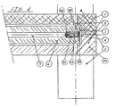
- Fig. 1 On Fig. 1 is shown the two mould parts 1 of the mould 10, which are closed together before moulding for forming a mould cavity 3. Inside this mould cavity 3 lies a mould core 6 which is to provide that the moulded item becomes hollow.
- This mould core 6 is supported by at least two support pins 2 which are drawn to and fro by means of hydraulic cylinders 5.
- the hydraulic cylinders 5 are retracted immediately before terminating the plastic injection. At the time when the cylinders are retracted, the mould cavity 3 is largely filled with plastic mass, after which mainly the volume of the pins 2 is only to be filled.
- the air venting valve 4 which is provide with pressurised air from an internal duct 7 in the mould core 6.
- the air venting valve 4 comprises a bearing 41 in which a piston 42 is disposed sliding in the longitudinal direction of the bearing 41.
- the piston 42 has a conical end 44 fitting tightly against a corresponding conical part 45 of the bearing 41.
- a spring 43 secures the piston 42 in the bearing 41 with the conical end 45 of the piston pressed against the corresponding conical part 44 of the bearing 41.
- the valve 4 When the valve 4 is closed, the plastic mass may therefore not be pressed into the inner duct 7. High pressure from the plastic mass will press the piston 42 against the conical part 45 of the bearing 41, whereby is achieved a more efficient sealing of the valve 4.
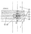
- Fig. 2 On Fig. 2 is shown an alternative embodiment.
- the mould core 6 may be displaced to and fro in the cavity 3 via a hydraulic cylinder.
- the mould core 6 is provided with a conical socket 9 at the free end corresponding to a conical projection 11 of the mould core.
- the conical socket 9 will receive the conical projection 11, whereby the mould core 6 becomes locked in a centred position.
- the cylindrical device shown on Fig. 2 acts according to purpose, also during rotation, though it is an advantage if the conical embodiment is provided with a rotatable bearing so that friction between the socket 9 of the mould core and the corresponding part 11 is avoided.
- the embodiment shown on Fig. 3 is advantageous.
- the support pins 2 may be squeezed against a rotatable bearing 12 with external bushing 13, which is secured between the support pins 2, while the mould core 6 rotates inside the rotatable bearing 12 with its end piece 14.
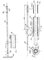
- Fig. 4 shows a handle 21 according to the invention with a grip 35 and a holder device 30 for auxiliary equipment 31, for example a broom.
- the handle 21 according to the invention is advantageously hollow as shown on Fig. 5, where a longitudinal hole 17 extends through the handle 21 with a wall 24, where the wall 24 is made of a thermoplastic polymer.
- An advantageous grip which is very user friendly, may e.g. consist of ball-shaped holder 32 at the end of the handle 21.
- the handle 21 may be provided with a ring 33 preventing the handle 21 from sliding out of the user's hand, when the handle 21 is in an approximately vertical position, e.g. by window cleaning or when painting facades.
- the ring 33, as well as the ball-shaped holder 32, are injection moulded onto the handle, preferably in a thermoplastic rubber. As the rubber by injection moulding on the polymer material of the handle 21 fuses with the handle 21, pockets or grooves at the transition from the grip 35 to the handle 21 are avoided.
- the holder device 30 for the auxiliary equipment 31 is separate and fitted on the handle 21, e.g. by gluing, plastic welding, or friction welding under rotation.
- the grip 35 is shown in cross-section with the handle 21 material 24 surrounding the hole 37 and surrounded by the other injection moulded material 25.
- the two polymer materials 24 and 25 are fused together, whereby liquid or bacteria cannot accumulate in a possible interspace between the two polymers.
- Fig. 6 shows handle 21 according to the invention with a telescoping device.
- the handle 21 is hollow with an internal diameter which is larger than the outer diameter of the tube 27 so that the tube 27 may be accommodated displacing in the handle 21.
- a clamping device 34 is used for locking the internal telescope tube 27 in relation to the handle 21.
- the clamping device 34 includes a swivel nut 23 which e.g. may be injection moulded in a thermoplastic polymer. This swivel nut has a conical, internal thread 19 that engages an external thread 20 of fingers 26 in extension of the handle 21.
- the conical thread 19 of the swivel nut will press the fingers 26 against the tube 27. Thereby friction between the fingers 26 and the tube 27 is increased, and the tube 27 is locked in relation to the handle 21.
- the thread 19 of the swivel nut 23 may be non-conical, while the thread 20 of the fingers is conical, whereby the same effect is achieved.
- the interspaces between the fingers 26 may be filled with rubber pads 28.
- these pads 28 will be pressed together.
- the elastic deformation of these pads 28 will lead to rubber material being pressed towards the tube 27 by the pads 28, resulting in increased friction against the tube 27.
- the collet chuck including the fingers 26 and the pads 28 is waterproof so that water cannot penetrate into the interspace between the tube 27 and the handle 21.
- the collet chuck may advantageously be provided with a rubber lip 29 extending around the end of the collet chuck 34 for pressing against the outer side of the tube 27.
- the tube 27 may advantageously be made in the same way as the handle 21.
- spherical holder 32 shown on Fig. 4 may be supplemented with or substituted by a suspension means, e.g. a hook or a hole.
- thermoplastic rubber on existing handles e.g. aluminium handles or thermosetting handles that are hollow
- high pressure is to be applied for moulding that these handles will collapse in such cases.
- thermoplastic rubber on a handle according to the invention is achieved in that already at the injection moulding of the hollow handle according to the invention there is provided a mould core in the shape of a mandrel inside the handle, preventing the hollow handle from collapsing.
- the invention is thus an overall solution meeting a number of purposes in a simple way.
- a handle according to the invention may also be provided with devices not being of thermoplastic polymer, however, with regard to recycling it is preferred that the entire handle including holder device is made of thermoplastic polymer.
Landscapes
- Engineering & Computer Science (AREA)
- Mechanical Engineering (AREA)
- Manufacturing & Machinery (AREA)
- Moulds For Moulding Plastics Or The Like (AREA)
- Injection Moulding Of Plastics Or The Like (AREA)
- Moulding By Coating Moulds (AREA)
Claims (17)
- Verfahren zum Kompaktspritzgießen eines langen, rohrförmigen Thermoplast-Artikels mit einer wenigstens teilweise durchgängigen Öffnung in Längsrichtung des Artikels, wobei das Verfahren beinhaltet:- Bereitstellen einer Spritzgießmaschine mit einer Form (10) mit Hohlraum (3), der ein inneres Volumen aufweist, welches die Maße des Artikels bestimmt, in welcher Form (10) ein Formkern (6) zum Ausbilden der wenigstens teilweise durchgängigen Öffnung in dem Artikel vorgesehen ist, wobei der Formkern an seinem ersten Ende aufgehängt ist,- Einspritzen von geschmolzenem thermoplastischem Material in den Hohlraum (3) der Form,- Verfestigen des geschmolzenen Kunststoffimaterials,- Öffnen der Form (10),- Entfernen des Artikels von dem Formkern (6),- Bereitstellen einer zentralen Halterung des Formkerns (6) an einem freien Abschnitt des Formkerns in einem bestimmten Abstand von dem ersten Ende des Formkerns (6) in der Form (10) zu Beginn des Einspritzens des geschmolzenen Kunststoffinaterials in die Form (14), und wobei der Formkern (6) vor dem Beenden des Einspritzens des Kunststoffinaterials von der Halterung freigegeben wird, um zu ermöglichen, dass die geschmolzene Kunststoffmasse den Hohlraum (3) zwischen der Innenwand der Form (10) und dem freien Abschnitt des Formkerns (6) füllt,dadurch gekennzeichnet, dass das Verfahren außerdem- ein Drehen wenigstens eines Teils des Formkerns (6) während wenigstens eines Teils des Einspritzens beinhaltet.
- Verfahren gemäß Anspruch 1, dadurch gekennzeichnet, dass das Drehen wenigstens eines Teils des Kerns während des Einspritzens der Kunststoffmasse bis unmittelbar vor Beendigung des Einspritzens erfolgt, wo das Drehen beendet wird.
- Verfahren gemäß Anspruch 1 oder 2, dadurch gekennzeichnet, dass die Halterung wenigstens zwei Stifte (2) aufweist, die jeweils mit ihrem ersten Ende gegen den freien Abschnitt (14) des Formkerns (6) auf gegenüberliegenden Seiten des Formkerns (6) lagern, wobei die Stifte (2) aus dem Hohlraum der Form (3) herausgezogen werden, um den Formkern (3) von der Halterung freizugeben.
- Verfahren gemäß Anspruch 3, dadurch gekennzeichnet, dass der Formkern (6) einen kreisförmigen Querschnitt aufweist und mit einem drehbaren Lager (12) versehen ist, welches zwischen den wenigstens zwei Stiften (2) zum Abstützen des Formkerns (6) festgeklemmt ist, wobei der Formkern (6) ein Teil aufweist, welches in dem Hohlraum der Form und innerhalb des drehbaren Lagers während des Einspritzens der Kunststoffmasse bis unmittelbar vor Beendigung des Einspritzens rotiert, wo die Rotation beendet wird und die Stifte (2) zurückgezogen werden, um den Formkern (6) aus der Halterung freizugeben.
- Verfahren gemäß Anspruch 1 oder 2, dadurch gekennzeichnet, dass die Halterung einen konischen Vorsprung (11) an der Endwand (15) der Form (10) und eine entsprechende konische Aufnahme (9) an dem Formkern (6) zum Aufnehmen des konischen Vorsprungs (11) aufweist, wobei der Formkern (6) unmittelbar vor Beendigung des Einspritzens des Kunststoffs zurückgezogen wird, um den Formkern (6) von der Halterung freizugeben.
- Verfahren gemäß einem der vorhergehenden Ansprüche, dadurch gekennzeichnet, dass der Formkern (6) mit einer inneren Leitung (7) zum Durchführen von Druckluft versehen ist, wobei der Kunststoffartikel von dem Formkern (6) entfernt wird, indem Druckluft durch die Leitung (7) hindurch und in das freie Ende des Formkerns (6) geblasen wird, so dass ein Druckluftpolster zwischen dem geformten Thermoplast-Artikel und dem Formkern (6) erzeugt wird, wobei der Artikel durch die Wirkung der Druckluft von dem Formkern (6) heruntergleitet.
- Verfahren gemäß einem der vorhergehenden Ansprüche, dadurch gekennzeichnet, dass das Verfahren außerdem einen Schritt des Spritzgießens beinhaltet, wobei thermoplastisches Gummi, beispielsweise SEBS oder EPDM, durch Spritzgießen auf den Kunststoffartikel aufgebracht wird, wobei das Gummi als wenigstens einer der Bestandteile der Gruppe gestaltet ist, die- eine glatte, rutschfeste Oberfläche auf dem Artikel,- eine mit Rillen versehene rutschfeste Oberfläche auf dem Artikel,- einen kugelförmigen Halter am Ende des Artikels,- eine ringförmige Halterung,- eine Haltevorrichtung für Zusatzausrüstung,- ein Aufhängemittel,- ein Infonnations-Etikett oder -Schild und- ein Firmenlogoenthält.
- Verwendung eines Verfahrens gemäß einem der Ansprüche 1-7 zum Herstellen eines Pneumatikzylinders, einer Gerüststange, eines Strukturelementes für Gitterwerk oder eines Griffes für Reinigungswerkzeuge wie zum Beispiel eines Besenstiels, oder von Griffen für Malerwerkzeuge.
- Rohrförmiger Artikel, welcher mit einem Verfahren gemäß einem der Ansprüche 1-7 hergestellt ist, dadurch gekennzeichnet, dass das Material des Artikels wenigstens ein thermoplastisches Polymer umfasst.
- Rohrförmiger Artikel gemäß Anspruch 9, dadurch gekennzeichnet, dass wenigstens eines der Polymere einen Elastizitätsmodul von mehr als 3000 MPa aufweist, gemessen entsprechend der Norm ISO 178.
- Rohrförmiger Artikel gemäß Anspruch 9 oder 10, dadurch gekennzeichnet, dass die Länge der teilweise durchgängigen Öffnung in dem Artikel wenigstens das Zwanzigfache des mittleren Durchmessers der Öffnung beträgt.
- Rohrförmiger Artikel gemäß einem der Ansprüche 9-11, dadurch gekennzeichnet, dass das Material ein preiswertes thermoplastisches Material wie zum Beispiel Poylypropylen mit einem verstärkenden Material ist, vorzugsweise wenigstens einem aus der Gruppe, die aus verstärkendem Material, Glasfaser, Kohlenstofffaser, Kevlarfaser, Pflanzenfaser, mineralischen Füllstoffen, Bariumsulfat, Talkumpulver und Kreide besteht.
- Rohrförmiger Artikel gemäß einem der Ansprüche 9-12, dadurch gekennzeichnet, dass der Durchmesser der Öffnung zwischen 18 mm und 32 mm beträgt.
- Rohrförmiger Artikel gemäß einem der Ansprüche 9-13, dadurch gekennzeichnet, dass der rohrförmige Artikel ein Griff (21) ist, der mit einem aus thermoplastischem Material geformten Klemmfutter (34) mit einem Außengewinde (20) und einer Mutter (23) mit Innengewinde (19) versehen ist, welches für ein Zusammenwirken mit dem Außengewinde (20) vorgesehen ist, um ein Rohr (27), welches von dem hohlen Griff (23) umschlossen wird, festzuklemmen, wobei das Rohr (27) in dem Griff teleskopartig gleiten kann.
- Rohrförmiger Artikel gemäß Anspruch 14, dadurch gekennzeichnet, dass das Klemmfutter (34) mit Fingern (26) aus thermoplastischem Polymer mit thermoplastischen Gummipolstern (28) zwischen den Fingern (26) versehen ist, so dass diese durch Anziehen der Mutter (23) auf dem Außengewinde (20) zusammen gegen das Rohr (27) pressen.
- Rohrförmiger Artikel gemäß Anspruch 15, dadurch gekennzeichnet, dass das Klemmfutter (34) am Ende der Finger eine Thermoplast-Gummilippe (29) aufweist.
- Form für ein Verfahren gemäß einem der Ansprüche 1-7, wobei der Formkern (6) für die Drehung in der Form gestaltet ist, enthaltend Mittel zum Abstützen des Formkerns in einem bestimmten Abstand von seinem drehbar aufgehängten Ende, um eine höhere Stabilität des Kerns während des Kunststoffformens zu erreichen, dadurch gekennzeichnet, dass die Form dafür konfiguriert ist, eine Abstützung des Kerns zu Beginn des Einspritzens herzustellen und die Abstützung des Kerns während des Einspritzens zu beenden.
Applications Claiming Priority (3)
| Application Number | Priority Date | Filing Date | Title |
|---|---|---|---|
| DK200200604 | 2002-04-23 | ||
| DK200200604A DK174823B1 (da) | 2002-04-23 | 2002-04-23 | Fremgangsmåde til termoplastisk støbning af et rørformet emne |
| PCT/DK2002/000611 WO2003090991A1 (en) | 2002-04-23 | 2002-09-20 | Method for thermoplastic moulding of a tubulant item, a tubular item and an injection mould with a rotating core |
Publications (2)
| Publication Number | Publication Date |
|---|---|
| EP1501667A1 EP1501667A1 (de) | 2005-02-02 |
| EP1501667B1 true EP1501667B1 (de) | 2007-05-30 |
Family
ID=29265857
Family Applications (1)
| Application Number | Title | Priority Date | Filing Date |
|---|---|---|---|
| EP02776901A Expired - Lifetime EP1501667B1 (de) | 2002-04-23 | 2002-09-20 | Verfahren zum thermoplastischen formen eines rohrförmigen gegenstands, rohrförmiger gegenstand und spritzgiessform mit einem drehkern |
Country Status (8)
| Country | Link |
|---|---|
| US (1) | US7429348B2 (de) |
| EP (1) | EP1501667B1 (de) |
| CN (1) | CN100467244C (de) |
| AT (1) | ATE363367T1 (de) |
| AU (1) | AU2002344038A1 (de) |
| DE (1) | DE60220453T2 (de) |
| DK (2) | DK174823B1 (de) |
| WO (1) | WO2003090991A1 (de) |
Families Citing this family (16)
| Publication number | Priority date | Publication date | Assignee | Title |
|---|---|---|---|---|
| EP2445566A1 (de) * | 2009-06-26 | 2012-05-02 | Coloplast A/S | Spritzgusskatheter |
| FI20096328A7 (fi) * | 2009-12-15 | 2011-06-16 | Fiskars Brands Finland Oy Ab | Menetelmä käsityökalun kädensijan valmistamiseksi ja käsityökalun kädensija |
| DE102010030286A1 (de) * | 2010-06-21 | 2011-12-22 | Walter Söhner GmbH & Co. KG | Verteiler für ein Einspritzsystem |
| US20130008033A1 (en) * | 2011-07-07 | 2013-01-10 | Louis Fortman | Multifunctional Gardening Tool |
| CN102358010B (zh) * | 2011-08-24 | 2013-08-28 | 江苏辉达塑模科技有限公司 | 塑料螺纹管件顶杆旋转自动顶出机构 |
| CN104441476A (zh) * | 2014-10-28 | 2015-03-25 | 苏州广型模具有限公司 | 底部可旋转的对开模具 |
| CN106113356B (zh) * | 2016-08-30 | 2019-04-30 | 重庆凯龙科技有限公司 | 传感器管路自动压塑装置 |
| ES3042609T3 (en) * | 2016-09-30 | 2025-11-21 | Braun B Med Sas | Method for manufacturing a urinary catheter, by injection moulding a thermoplastic material in a mould |
| US10179433B2 (en) * | 2017-03-02 | 2019-01-15 | Ford Global Technologies, Llc | Method of forming a headrest assembly |
| WO2019111881A1 (ja) * | 2017-12-07 | 2019-06-13 | 日東電工株式会社 | 支持体の製造方法 |
| EP3695948B1 (de) * | 2019-02-15 | 2021-11-24 | Tetra Laval Holdings & Finance S.A. | Spritzgiessform umfassend ein inneres formteil |
| CN110406046B (zh) * | 2019-08-29 | 2024-11-08 | 珠海格力精密模具有限公司 | 一种新型模具定位止转装置 |
| CN110900994B (zh) * | 2019-12-17 | 2021-11-09 | 上安实业江苏有限公司 | 一种形态自控且破损小的模具用后腔顶出装置 |
| CN111251515B (zh) * | 2020-01-20 | 2022-01-07 | 鸿利达模具(深圳)有限公司 | 一种医疗器件检测脱模设备 |
| CN116710259B (zh) * | 2020-12-29 | 2025-10-31 | 乐高公司 | 用于注射模制的模具 |
| CN112936749B (zh) * | 2021-01-27 | 2022-08-09 | 乐之宝(东莞)文化创意有限公司 | 一种均匀射胶的双色注塑模具 |
Family Cites Families (15)
| Publication number | Priority date | Publication date | Assignee | Title |
|---|---|---|---|---|
| US4345351A (en) | 1981-03-02 | 1982-08-24 | Seco Industries, Inc. | Extension handle for dust mops and the like |
| US4929007A (en) * | 1987-03-30 | 1990-05-29 | Magna International Inc. | Latch mechanism |
| JPH01148524A (ja) * | 1987-12-04 | 1989-06-09 | Sumitomo Heavy Ind Ltd | 入子式コア回転金型装置 |
| CA2071859A1 (en) | 1989-12-15 | 1991-06-16 | Geoffrey P. Motley | Hockey stick |
| US5240397A (en) * | 1991-10-01 | 1993-08-31 | Biomedical Polymers, Inc. | Injection molding mechanism for forming a monolithic tubular pipette |
| JPH06126780A (ja) * | 1992-10-16 | 1994-05-10 | Meihoo:Kk | 高精度の穴をもつプラスチック製品 |
| US5352398A (en) * | 1993-05-06 | 1994-10-04 | Eastman Kodak Company | Apparatus and method for attaching a cap to a mold core |
| JP2537131B2 (ja) * | 1993-06-28 | 1996-09-25 | 株式会社メイホー | 高精度のパイプとこのパイプの製造方法 |
| CN2250233Y (zh) * | 1996-04-05 | 1997-03-26 | 李钟镐 | 内壁形成螺旋形凸起的排水管材的压出成型装置 |
| DE29706893U1 (de) * | 1997-04-16 | 1997-09-04 | Leh, Norbert, 85049 Ingolstadt | Einsteckhalterung für Flachgriffpinsel (Heizkörperpinsel) |
| US5983455A (en) * | 1997-06-19 | 1999-11-16 | Newell Operating Company | Multi-faceted extension pole |
| US5964009A (en) | 1997-09-15 | 1999-10-12 | Snap-On Technologies, Inc. | Tool with dual-material handle |
| CN1058654C (zh) * | 1997-11-26 | 2000-11-22 | 金学厚 | 以熔体压力为驱动源的塑料旋转挤出法 |
| SE0003117D0 (sv) | 2000-09-03 | 2000-09-03 | Fast Industriprodukter Hb | Anordning för inbördes fixering av i varandra teleskopiskt förskjutna element |
| WO2002034494A1 (en) * | 2000-10-24 | 2002-05-02 | Vikan A/S | Method for moulding a tool handle |
-
2002
- 2002-04-23 DK DK200200604A patent/DK174823B1/da not_active IP Right Cessation
- 2002-09-20 DK DK02776901T patent/DK1501667T3/da active
- 2002-09-20 WO PCT/DK2002/000611 patent/WO2003090991A1/en not_active Ceased
- 2002-09-20 EP EP02776901A patent/EP1501667B1/de not_active Expired - Lifetime
- 2002-09-20 US US10/512,203 patent/US7429348B2/en not_active Expired - Lifetime
- 2002-09-20 AT AT02776901T patent/ATE363367T1/de not_active IP Right Cessation
- 2002-09-20 DE DE60220453T patent/DE60220453T2/de not_active Expired - Lifetime
- 2002-09-20 AU AU2002344038A patent/AU2002344038A1/en not_active Abandoned
- 2002-09-20 CN CNB028290151A patent/CN100467244C/zh not_active Expired - Lifetime
Also Published As
| Publication number | Publication date |
|---|---|
| US20050112309A1 (en) | 2005-05-26 |
| DE60220453D1 (de) | 2007-07-12 |
| WO2003090991A1 (en) | 2003-11-06 |
| ATE363367T1 (de) | 2007-06-15 |
| DE60220453T2 (de) | 2008-01-31 |
| AU2002344038A1 (en) | 2003-11-10 |
| US7429348B2 (en) | 2008-09-30 |
| CN1628017A (zh) | 2005-06-15 |
| EP1501667A1 (de) | 2005-02-02 |
| DK1501667T3 (da) | 2007-09-24 |
| DK174823B1 (da) | 2003-12-08 |
| CN100467244C (zh) | 2009-03-11 |
Similar Documents
| Publication | Publication Date | Title |
|---|---|---|
| EP1501667B1 (de) | Verfahren zum thermoplastischen formen eines rohrförmigen gegenstands, rohrförmiger gegenstand und spritzgiessform mit einem drehkern | |
| EP2782474B1 (de) | Verfahren zur herstellung einer zahnbürste mit einem innenhohlraum | |
| US6910596B2 (en) | Water bottle with handle | |
| US9420877B2 (en) | Method for producing a toothbrush having an inner cavity | |
| CA2437934A1 (en) | Method for manufacturing fiber reinforced rod | |
| US20070190275A1 (en) | Method for the production of a flexible tube | |
| CN110271138A (zh) | 空心型材复合技术 | |
| EP1763427A1 (de) | Kunststoffbehälter, insbesondere kunstoffflasche, mit angeformtem griffteil, preformling und herstellverfahren für die kunststoffflasche | |
| EP1379394B1 (de) | Herstellung von druckzylindern | |
| CN206242455U (zh) | 一种挤出机套筒清理装置 | |
| AU757609B2 (en) | removable tip dispensing closure and method of manufacture | |
| CN115256810A (zh) | 一种聚乙烯注射成形设备及其生产方法 | |
| HU225665B1 (en) | Device and method for producing hollow bodies | |
| CN211118064U (zh) | 一种新型hdpe缠绕管 | |
| CN211518246U (zh) | 一种管道内壁涂层浇铸的模具 | |
| CN214605831U (zh) | 一种适于淀粉生物降解材料的吹膜机旋转模头 | |
| WO2001076853A3 (en) | Fiber reinforced threaded rod | |
| CN220681430U (zh) | 一种注塑机防堵机构 | |
| CN220883259U (zh) | 用于塑料注塑模具的抽芯结构 | |
| CN110919477A (zh) | 一种金属制品拉丝工艺用拉丝模具 | |
| CN223100026U (zh) | 一种注射装置、树脂在线改性成型设备 | |
| CN217972559U (zh) | 一种工程机械用防锈蜡灌装装置 | |
| CN215703587U (zh) | 一种用于塑料件注塑的模具喷嘴 | |
| JP2561582B2 (ja) | ブロ−成形機におけるパリソン射出ダイスおよび樹脂替え方法 | |
| CN212472123U (zh) | 一种便于清洗的环保可降解餐具加工模具 |
Legal Events
| Date | Code | Title | Description |
|---|---|---|---|
| PUAI | Public reference made under article 153(3) epc to a published international application that has entered the european phase |
Free format text: ORIGINAL CODE: 0009012 |
|
| 17P | Request for examination filed |
Effective date: 20041117 |
|
| AK | Designated contracting states |
Kind code of ref document: A1 Designated state(s): AT BE BG CH CY CZ DE DK EE ES FI FR GB GR IE IT LI LU MC |
|
| AX | Request for extension of the european patent |
Extension state: AL LT LV MK RO SI |
|
| GRAP | Despatch of communication of intention to grant a patent |
Free format text: ORIGINAL CODE: EPIDOSNIGR1 |
|
| GRAC | Information related to communication of intention to grant a patent modified |
Free format text: ORIGINAL CODE: EPIDOSCIGR1 |
|
| RBV | Designated contracting states (corrected) |
Designated state(s): AT BE BG CH CY CZ DE DK EE ES FI FR GB GR IE IT LI LU MC NL PT SE SK TR |
|
| GRAS | Grant fee paid |
Free format text: ORIGINAL CODE: EPIDOSNIGR3 |
|
| GRAA | (expected) grant |
Free format text: ORIGINAL CODE: 0009210 |
|
| AK | Designated contracting states |
Kind code of ref document: B1 Designated state(s): AT BE BG CH CY CZ DE DK EE ES FI FR GB GR IE IT LI LU MC NL PT SE SK TR |
|
| AX | Request for extension of the european patent |
Extension state: LT LV SI |
|
| PG25 | Lapsed in a contracting state [announced via postgrant information from national office to epo] |
Ref country code: CH Free format text: LAPSE BECAUSE OF FAILURE TO SUBMIT A TRANSLATION OF THE DESCRIPTION OR TO PAY THE FEE WITHIN THE PRESCRIBED TIME-LIMIT Effective date: 20070530 Ref country code: LI Free format text: LAPSE BECAUSE OF FAILURE TO SUBMIT A TRANSLATION OF THE DESCRIPTION OR TO PAY THE FEE WITHIN THE PRESCRIBED TIME-LIMIT Effective date: 20070530 Ref country code: FI Free format text: LAPSE BECAUSE OF FAILURE TO SUBMIT A TRANSLATION OF THE DESCRIPTION OR TO PAY THE FEE WITHIN THE PRESCRIBED TIME-LIMIT Effective date: 20070530 |
|
| REG | Reference to a national code |
Ref country code: GB Ref legal event code: FG4D |
|
| REG | Reference to a national code |
Ref country code: CH Ref legal event code: EP |
|
| REG | Reference to a national code |
Ref country code: IE Ref legal event code: FG4D |
|
| REF | Corresponds to: |
Ref document number: 60220453 Country of ref document: DE Date of ref document: 20070712 Kind code of ref document: P |
|
| PG25 | Lapsed in a contracting state [announced via postgrant information from national office to epo] |
Ref country code: SE Free format text: LAPSE BECAUSE OF FAILURE TO SUBMIT A TRANSLATION OF THE DESCRIPTION OR TO PAY THE FEE WITHIN THE PRESCRIBED TIME-LIMIT Effective date: 20070830 |
|
| PG25 | Lapsed in a contracting state [announced via postgrant information from national office to epo] |
Ref country code: ES Free format text: LAPSE BECAUSE OF FAILURE TO SUBMIT A TRANSLATION OF THE DESCRIPTION OR TO PAY THE FEE WITHIN THE PRESCRIBED TIME-LIMIT Effective date: 20070910 |
|
| PG25 | Lapsed in a contracting state [announced via postgrant information from national office to epo] |
Ref country code: AT Free format text: LAPSE BECAUSE OF FAILURE TO SUBMIT A TRANSLATION OF THE DESCRIPTION OR TO PAY THE FEE WITHIN THE PRESCRIBED TIME-LIMIT Effective date: 20070530 |
|
| LTIE | Lt: invalidation of european patent or patent extension |
Effective date: 20070530 |
|
| ET | Fr: translation filed | ||
| NLV1 | Nl: lapsed or annulled due to failure to fulfill the requirements of art. 29p and 29m of the patents act | ||
| REG | Reference to a national code |
Ref country code: CH Ref legal event code: PL |
|
| PG25 | Lapsed in a contracting state [announced via postgrant information from national office to epo] |
Ref country code: BE Free format text: LAPSE BECAUSE OF FAILURE TO SUBMIT A TRANSLATION OF THE DESCRIPTION OR TO PAY THE FEE WITHIN THE PRESCRIBED TIME-LIMIT Effective date: 20070530 |
|
| PG25 | Lapsed in a contracting state [announced via postgrant information from national office to epo] |
Ref country code: BG Free format text: LAPSE BECAUSE OF FAILURE TO SUBMIT A TRANSLATION OF THE DESCRIPTION OR TO PAY THE FEE WITHIN THE PRESCRIBED TIME-LIMIT Effective date: 20070830 Ref country code: CZ Free format text: LAPSE BECAUSE OF FAILURE TO SUBMIT A TRANSLATION OF THE DESCRIPTION OR TO PAY THE FEE WITHIN THE PRESCRIBED TIME-LIMIT Effective date: 20070530 Ref country code: NL Free format text: LAPSE BECAUSE OF FAILURE TO SUBMIT A TRANSLATION OF THE DESCRIPTION OR TO PAY THE FEE WITHIN THE PRESCRIBED TIME-LIMIT Effective date: 20070530 |
|
| PG25 | Lapsed in a contracting state [announced via postgrant information from national office to epo] |
Ref country code: SK Free format text: LAPSE BECAUSE OF FAILURE TO SUBMIT A TRANSLATION OF THE DESCRIPTION OR TO PAY THE FEE WITHIN THE PRESCRIBED TIME-LIMIT Effective date: 20070530 |
|
| PLBE | No opposition filed within time limit |
Free format text: ORIGINAL CODE: 0009261 |
|
| STAA | Information on the status of an ep patent application or granted ep patent |
Free format text: STATUS: NO OPPOSITION FILED WITHIN TIME LIMIT |
|
| PG25 | Lapsed in a contracting state [announced via postgrant information from national office to epo] |
Ref country code: GR Free format text: LAPSE BECAUSE OF FAILURE TO SUBMIT A TRANSLATION OF THE DESCRIPTION OR TO PAY THE FEE WITHIN THE PRESCRIBED TIME-LIMIT Effective date: 20070831 Ref country code: MC Free format text: LAPSE BECAUSE OF NON-PAYMENT OF DUE FEES Effective date: 20070930 |
|
| 26N | No opposition filed |
Effective date: 20080303 |
|
| PG25 | Lapsed in a contracting state [announced via postgrant information from national office to epo] |
Ref country code: IE Free format text: LAPSE BECAUSE OF NON-PAYMENT OF DUE FEES Effective date: 20070920 |
|
| PG25 | Lapsed in a contracting state [announced via postgrant information from national office to epo] |
Ref country code: EE Free format text: LAPSE BECAUSE OF FAILURE TO SUBMIT A TRANSLATION OF THE DESCRIPTION OR TO PAY THE FEE WITHIN THE PRESCRIBED TIME-LIMIT Effective date: 20070530 |
|
| PG25 | Lapsed in a contracting state [announced via postgrant information from national office to epo] |
Ref country code: CY Free format text: LAPSE BECAUSE OF FAILURE TO SUBMIT A TRANSLATION OF THE DESCRIPTION OR TO PAY THE FEE WITHIN THE PRESCRIBED TIME-LIMIT Effective date: 20070530 |
|
| PG25 | Lapsed in a contracting state [announced via postgrant information from national office to epo] |
Ref country code: LU Free format text: LAPSE BECAUSE OF NON-PAYMENT OF DUE FEES Effective date: 20070920 |
|
| PG25 | Lapsed in a contracting state [announced via postgrant information from national office to epo] |
Ref country code: TR Free format text: LAPSE BECAUSE OF FAILURE TO SUBMIT A TRANSLATION OF THE DESCRIPTION OR TO PAY THE FEE WITHIN THE PRESCRIBED TIME-LIMIT Effective date: 20070530 |
|
| PG25 | Lapsed in a contracting state [announced via postgrant information from national office to epo] |
Ref country code: PT Free format text: LAPSE BECAUSE OF FAILURE TO SUBMIT A TRANSLATION OF THE DESCRIPTION OR TO PAY THE FEE WITHIN THE PRESCRIBED TIME-LIMIT Effective date: 20070530 |
|
| REG | Reference to a national code |
Ref country code: FR Ref legal event code: PLFP Year of fee payment: 14 |
|
| REG | Reference to a national code |
Ref country code: FR Ref legal event code: PLFP Year of fee payment: 15 |
|
| REG | Reference to a national code |
Ref country code: FR Ref legal event code: PLFP Year of fee payment: 16 |
|
| REG | Reference to a national code |
Ref country code: FR Ref legal event code: PLFP Year of fee payment: 17 |
|
| PGFP | Annual fee paid to national office [announced via postgrant information from national office to epo] |
Ref country code: FR Payment date: 20190925 Year of fee payment: 18 Ref country code: IT Payment date: 20190920 Year of fee payment: 18 |
|
| PGFP | Annual fee paid to national office [announced via postgrant information from national office to epo] |
Ref country code: GB Payment date: 20190927 Year of fee payment: 18 |
|
| PGFP | Annual fee paid to national office [announced via postgrant information from national office to epo] |
Ref country code: DE Payment date: 20190927 Year of fee payment: 18 |
|
| REG | Reference to a national code |
Ref country code: DE Ref legal event code: R119 Ref document number: 60220453 Country of ref document: DE |
|
| GBPC | Gb: european patent ceased through non-payment of renewal fee |
Effective date: 20200920 |
|
| PG25 | Lapsed in a contracting state [announced via postgrant information from national office to epo] |
Ref country code: FR Free format text: LAPSE BECAUSE OF NON-PAYMENT OF DUE FEES Effective date: 20200930 Ref country code: DE Free format text: LAPSE BECAUSE OF NON-PAYMENT OF DUE FEES Effective date: 20210401 |
|
| PG25 | Lapsed in a contracting state [announced via postgrant information from national office to epo] |
Ref country code: GB Free format text: LAPSE BECAUSE OF NON-PAYMENT OF DUE FEES Effective date: 20200920 |
|
| PGFP | Annual fee paid to national office [announced via postgrant information from national office to epo] |
Ref country code: DK Payment date: 20210929 Year of fee payment: 20 |
|
| PG25 | Lapsed in a contracting state [announced via postgrant information from national office to epo] |
Ref country code: IT Free format text: LAPSE BECAUSE OF NON-PAYMENT OF DUE FEES Effective date: 20200920 |
|
| REG | Reference to a national code |
Ref country code: DK Ref legal event code: EUP Expiry date: 20220920 |