EP1501401B1 - Vaskulare Schutzvorrichtung für Blut - Google Patents
Vaskulare Schutzvorrichtung für Blut Download PDFInfo
- Publication number
- EP1501401B1 EP1501401B1 EP03721893A EP03721893A EP1501401B1 EP 1501401 B1 EP1501401 B1 EP 1501401B1 EP 03721893 A EP03721893 A EP 03721893A EP 03721893 A EP03721893 A EP 03721893A EP 1501401 B1 EP1501401 B1 EP 1501401B1
- Authority
- EP
- European Patent Office
- Prior art keywords
- filter
- distal
- proximal
- elongate support
- support member
- Prior art date
- Legal status (The legal status is an assumption and is not a legal conclusion. Google has not performed a legal analysis and makes no representation as to the accuracy of the status listed.)
- Expired - Lifetime
Links
Images


Classifications
-
- A—HUMAN NECESSITIES
- A61—MEDICAL OR VETERINARY SCIENCE; HYGIENE
- A61F—FILTERS IMPLANTABLE INTO BLOOD VESSELS; PROSTHESES; DEVICES PROVIDING PATENCY TO, OR PREVENTING COLLAPSING OF, TUBULAR STRUCTURES OF THE BODY, e.g. STENTS; ORTHOPAEDIC, NURSING OR CONTRACEPTIVE DEVICES; FOMENTATION; TREATMENT OR PROTECTION OF EYES OR EARS; BANDAGES, DRESSINGS OR ABSORBENT PADS; FIRST-AID KITS
- A61F2/00—Filters implantable into blood vessels; Prostheses, i.e. artificial substitutes or replacements for parts of the body; Appliances for connecting them with the body; Devices providing patency to, or preventing collapsing of, tubular structures of the body, e.g. stents
- A61F2/01—Filters implantable into blood vessels
- A61F2/013—Distal protection devices, i.e. devices placed distally in combination with another endovascular procedure, e.g. angioplasty or stenting
-
- A—HUMAN NECESSITIES
- A61—MEDICAL OR VETERINARY SCIENCE; HYGIENE
- A61B—DIAGNOSIS; SURGERY; IDENTIFICATION
- A61B17/00—Surgical instruments, devices or methods
- A61B17/12—Surgical instruments, devices or methods for ligaturing or otherwise compressing tubular parts of the body, e.g. blood vessels or umbilical cord
- A61B17/12022—Occluding by internal devices, e.g. balloons or releasable wires
- A61B17/12131—Occluding by internal devices, e.g. balloons or releasable wires characterised by the type of occluding device
- A61B17/12168—Occluding by internal devices, e.g. balloons or releasable wires characterised by the type of occluding device having a mesh structure
- A61B17/12172—Occluding by internal devices, e.g. balloons or releasable wires characterised by the type of occluding device having a mesh structure having a pre-set deployed three-dimensional shape
-
- A—HUMAN NECESSITIES
- A61—MEDICAL OR VETERINARY SCIENCE; HYGIENE
- A61B—DIAGNOSIS; SURGERY; IDENTIFICATION
- A61B17/00—Surgical instruments, devices or methods
- A61B17/22—Implements for squeezing-off ulcers or the like on inner organs of the body; Implements for scraping-out cavities of body organs, e.g. bones; for invasive removal or destruction of calculus using mechanical vibrations; for removing obstructions in blood vessels, not otherwise provided for
- A61B17/221—Gripping devices in the form of loops or baskets for gripping calculi or similar types of obstructions
-
- A—HUMAN NECESSITIES
- A61—MEDICAL OR VETERINARY SCIENCE; HYGIENE
- A61M—DEVICES FOR INTRODUCING MEDIA INTO, OR ONTO, THE BODY; DEVICES FOR TRANSDUCING BODY MEDIA OR FOR TAKING MEDIA FROM THE BODY; DEVICES FOR PRODUCING OR ENDING SLEEP OR STUPOR
- A61M25/00—Catheters; Hollow probes
- A61M25/01—Introducing, guiding, advancing, emplacing or holding catheters
- A61M25/09—Guide wires
-
- A—HUMAN NECESSITIES
- A61—MEDICAL OR VETERINARY SCIENCE; HYGIENE
- A61B—DIAGNOSIS; SURGERY; IDENTIFICATION
- A61B17/00—Surgical instruments, devices or methods
- A61B17/12—Surgical instruments, devices or methods for ligaturing or otherwise compressing tubular parts of the body, e.g. blood vessels or umbilical cord
- A61B17/12022—Occluding by internal devices, e.g. balloons or releasable wires
-
- A—HUMAN NECESSITIES
- A61—MEDICAL OR VETERINARY SCIENCE; HYGIENE
- A61B—DIAGNOSIS; SURGERY; IDENTIFICATION
- A61B17/00—Surgical instruments, devices or methods
- A61B2017/00831—Material properties
- A61B2017/00867—Material properties shape memory effect
-
- A—HUMAN NECESSITIES
- A61—MEDICAL OR VETERINARY SCIENCE; HYGIENE
- A61B—DIAGNOSIS; SURGERY; IDENTIFICATION
- A61B17/00—Surgical instruments, devices or methods
- A61B17/22—Implements for squeezing-off ulcers or the like on inner organs of the body; Implements for scraping-out cavities of body organs, e.g. bones; for invasive removal or destruction of calculus using mechanical vibrations; for removing obstructions in blood vessels, not otherwise provided for
- A61B2017/22038—Implements for squeezing-off ulcers or the like on inner organs of the body; Implements for scraping-out cavities of body organs, e.g. bones; for invasive removal or destruction of calculus using mechanical vibrations; for removing obstructions in blood vessels, not otherwise provided for with a guide wire
- A61B2017/22045—Implements for squeezing-off ulcers or the like on inner organs of the body; Implements for scraping-out cavities of body organs, e.g. bones; for invasive removal or destruction of calculus using mechanical vibrations; for removing obstructions in blood vessels, not otherwise provided for with a guide wire fixed to the catheter; guiding tip
-
- A—HUMAN NECESSITIES
- A61—MEDICAL OR VETERINARY SCIENCE; HYGIENE
- A61F—FILTERS IMPLANTABLE INTO BLOOD VESSELS; PROSTHESES; DEVICES PROVIDING PATENCY TO, OR PREVENTING COLLAPSING OF, TUBULAR STRUCTURES OF THE BODY, e.g. STENTS; ORTHOPAEDIC, NURSING OR CONTRACEPTIVE DEVICES; FOMENTATION; TREATMENT OR PROTECTION OF EYES OR EARS; BANDAGES, DRESSINGS OR ABSORBENT PADS; FIRST-AID KITS
- A61F2/00—Filters implantable into blood vessels; Prostheses, i.e. artificial substitutes or replacements for parts of the body; Appliances for connecting them with the body; Devices providing patency to, or preventing collapsing of, tubular structures of the body, e.g. stents
- A61F2/01—Filters implantable into blood vessels
- A61F2/013—Distal protection devices, i.e. devices placed distally in combination with another endovascular procedure, e.g. angioplasty or stenting
- A61F2002/015—Stop means therefor
-
- A—HUMAN NECESSITIES
- A61—MEDICAL OR VETERINARY SCIENCE; HYGIENE
- A61F—FILTERS IMPLANTABLE INTO BLOOD VESSELS; PROSTHESES; DEVICES PROVIDING PATENCY TO, OR PREVENTING COLLAPSING OF, TUBULAR STRUCTURES OF THE BODY, e.g. STENTS; ORTHOPAEDIC, NURSING OR CONTRACEPTIVE DEVICES; FOMENTATION; TREATMENT OR PROTECTION OF EYES OR EARS; BANDAGES, DRESSINGS OR ABSORBENT PADS; FIRST-AID KITS
- A61F2/00—Filters implantable into blood vessels; Prostheses, i.e. artificial substitutes or replacements for parts of the body; Appliances for connecting them with the body; Devices providing patency to, or preventing collapsing of, tubular structures of the body, e.g. stents
- A61F2/01—Filters implantable into blood vessels
- A61F2002/018—Filters implantable into blood vessels made from tubes or sheets of material, e.g. by etching or laser-cutting
-
- A—HUMAN NECESSITIES
- A61—MEDICAL OR VETERINARY SCIENCE; HYGIENE
- A61F—FILTERS IMPLANTABLE INTO BLOOD VESSELS; PROSTHESES; DEVICES PROVIDING PATENCY TO, OR PREVENTING COLLAPSING OF, TUBULAR STRUCTURES OF THE BODY, e.g. STENTS; ORTHOPAEDIC, NURSING OR CONTRACEPTIVE DEVICES; FOMENTATION; TREATMENT OR PROTECTION OF EYES OR EARS; BANDAGES, DRESSINGS OR ABSORBENT PADS; FIRST-AID KITS
- A61F2230/00—Geometry of prostheses classified in groups A61F2/00 - A61F2/26 or A61F2/82 or A61F9/00 or A61F11/00 or subgroups thereof
- A61F2230/0002—Two-dimensional shapes, e.g. cross-sections
- A61F2230/0004—Rounded shapes, e.g. with rounded corners
- A61F2230/0006—Rounded shapes, e.g. with rounded corners circular
-
- A—HUMAN NECESSITIES
- A61—MEDICAL OR VETERINARY SCIENCE; HYGIENE
- A61F—FILTERS IMPLANTABLE INTO BLOOD VESSELS; PROSTHESES; DEVICES PROVIDING PATENCY TO, OR PREVENTING COLLAPSING OF, TUBULAR STRUCTURES OF THE BODY, e.g. STENTS; ORTHOPAEDIC, NURSING OR CONTRACEPTIVE DEVICES; FOMENTATION; TREATMENT OR PROTECTION OF EYES OR EARS; BANDAGES, DRESSINGS OR ABSORBENT PADS; FIRST-AID KITS
- A61F2230/00—Geometry of prostheses classified in groups A61F2/00 - A61F2/26 or A61F2/82 or A61F9/00 or A61F11/00 or subgroups thereof
- A61F2230/0002—Two-dimensional shapes, e.g. cross-sections
- A61F2230/0004—Rounded shapes, e.g. with rounded corners
- A61F2230/0008—Rounded shapes, e.g. with rounded corners elliptical or oval
-
- A—HUMAN NECESSITIES
- A61—MEDICAL OR VETERINARY SCIENCE; HYGIENE
- A61F—FILTERS IMPLANTABLE INTO BLOOD VESSELS; PROSTHESES; DEVICES PROVIDING PATENCY TO, OR PREVENTING COLLAPSING OF, TUBULAR STRUCTURES OF THE BODY, e.g. STENTS; ORTHOPAEDIC, NURSING OR CONTRACEPTIVE DEVICES; FOMENTATION; TREATMENT OR PROTECTION OF EYES OR EARS; BANDAGES, DRESSINGS OR ABSORBENT PADS; FIRST-AID KITS
- A61F2230/00—Geometry of prostheses classified in groups A61F2/00 - A61F2/26 or A61F2/82 or A61F9/00 or A61F11/00 or subgroups thereof
- A61F2230/0063—Three-dimensional shapes
- A61F2230/0067—Three-dimensional shapes conical
-
- A—HUMAN NECESSITIES
- A61—MEDICAL OR VETERINARY SCIENCE; HYGIENE
- A61F—FILTERS IMPLANTABLE INTO BLOOD VESSELS; PROSTHESES; DEVICES PROVIDING PATENCY TO, OR PREVENTING COLLAPSING OF, TUBULAR STRUCTURES OF THE BODY, e.g. STENTS; ORTHOPAEDIC, NURSING OR CONTRACEPTIVE DEVICES; FOMENTATION; TREATMENT OR PROTECTION OF EYES OR EARS; BANDAGES, DRESSINGS OR ABSORBENT PADS; FIRST-AID KITS
- A61F2230/00—Geometry of prostheses classified in groups A61F2/00 - A61F2/26 or A61F2/82 or A61F9/00 or A61F11/00 or subgroups thereof
- A61F2230/0063—Three-dimensional shapes
- A61F2230/0073—Quadric-shaped
- A61F2230/008—Quadric-shaped paraboloidal
-
- A—HUMAN NECESSITIES
- A61—MEDICAL OR VETERINARY SCIENCE; HYGIENE
- A61F—FILTERS IMPLANTABLE INTO BLOOD VESSELS; PROSTHESES; DEVICES PROVIDING PATENCY TO, OR PREVENTING COLLAPSING OF, TUBULAR STRUCTURES OF THE BODY, e.g. STENTS; ORTHOPAEDIC, NURSING OR CONTRACEPTIVE DEVICES; FOMENTATION; TREATMENT OR PROTECTION OF EYES OR EARS; BANDAGES, DRESSINGS OR ABSORBENT PADS; FIRST-AID KITS
- A61F2230/00—Geometry of prostheses classified in groups A61F2/00 - A61F2/26 or A61F2/82 or A61F9/00 or A61F11/00 or subgroups thereof
- A61F2230/0063—Three-dimensional shapes
- A61F2230/0093—Umbrella-shaped, e.g. mushroom-shaped
-
- A—HUMAN NECESSITIES
- A61—MEDICAL OR VETERINARY SCIENCE; HYGIENE
- A61M—DEVICES FOR INTRODUCING MEDIA INTO, OR ONTO, THE BODY; DEVICES FOR TRANSDUCING BODY MEDIA OR FOR TAKING MEDIA FROM THE BODY; DEVICES FOR PRODUCING OR ENDING SLEEP OR STUPOR
- A61M25/00—Catheters; Hollow probes
- A61M25/0067—Catheters; Hollow probes characterised by the distal end, e.g. tips
- A61M25/0074—Dynamic characteristics of the catheter tip, e.g. openable, closable, expandable or deformable
- A61M2025/0079—Separate user-activated means, e.g. guidewires, guide tubes, balloon catheters or sheaths, for sealing off an orifice, e.g. a lumen or side holes, of a catheter
-
- A—HUMAN NECESSITIES
- A61—MEDICAL OR VETERINARY SCIENCE; HYGIENE
- A61M—DEVICES FOR INTRODUCING MEDIA INTO, OR ONTO, THE BODY; DEVICES FOR TRANSDUCING BODY MEDIA OR FOR TAKING MEDIA FROM THE BODY; DEVICES FOR PRODUCING OR ENDING SLEEP OR STUPOR
- A61M25/00—Catheters; Hollow probes
- A61M25/01—Introducing, guiding, advancing, emplacing or holding catheters
- A61M25/09—Guide wires
- A61M2025/09175—Guide wires having specific characteristics at the distal tip
- A61M2025/09183—Guide wires having specific characteristics at the distal tip having tools at the distal tip
-
- A—HUMAN NECESSITIES
- A61—MEDICAL OR VETERINARY SCIENCE; HYGIENE
- A61M—DEVICES FOR INTRODUCING MEDIA INTO, OR ONTO, THE BODY; DEVICES FOR TRANSDUCING BODY MEDIA OR FOR TAKING MEDIA FROM THE BODY; DEVICES FOR PRODUCING OR ENDING SLEEP OR STUPOR
- A61M25/00—Catheters; Hollow probes
- A61M25/0067—Catheters; Hollow probes characterised by the distal end, e.g. tips
- A61M25/0074—Dynamic characteristics of the catheter tip, e.g. openable, closable, expandable or deformable
-
- A—HUMAN NECESSITIES
- A61—MEDICAL OR VETERINARY SCIENCE; HYGIENE
- A61M—DEVICES FOR INTRODUCING MEDIA INTO, OR ONTO, THE BODY; DEVICES FOR TRANSDUCING BODY MEDIA OR FOR TAKING MEDIA FROM THE BODY; DEVICES FOR PRODUCING OR ENDING SLEEP OR STUPOR
- A61M25/00—Catheters; Hollow probes
- A61M25/0067—Catheters; Hollow probes characterised by the distal end, e.g. tips
- A61M25/0082—Catheter tip comprising a tool
Definitions
- This invention relates to devices used in a blood vessel or other lumen in a patient's body.
- distal protection devices include filters and occlusive devices, (e.g., balloons) placed distally of the treatment site.
- a distal protection device it is desirable to place a distal protection device at a chosen location in order to achieve good sealing between the device and the wall of the vessel. Frequently it is necessary to match the protection device diameter with the vessel diameter, and vessels are known to taper or to have diameters that vary due to disease. It is also desirable to place the protection device in a relatively disease free portion of the vessel so as to minimize liberation or emboli from the wall of the vessel due to interaction with the protection device. Further, it is desirable that the device remains at the desired location during the procedure.
- Distal protection devices typically are mounted on a wire or tube that functions as a guidewire.
- the distal protection devices are either fixedly attached to the guidewire or attached so as to permit a limited amount of motion between the device and the guidewire.
- the same guidewire used to carry the device is also used to guide various catheters to and from the treatment site. For example, during the procedure, catheters may be exchanged over this guidewire.
- the wire or tube comprising the guidewire typically passes through or alongside the filter and terminates in an atraumatic tip.
- This arrangement helps assure correct deployment of the distal protection device.
- a disadvantage to this, however, is that a continuous wire or tube has a stiffness that can cause vessel damage. Inadvertent axial motion of the wire or tube can also dislodge emboli. Because the wire or tube is stiff, the vessel within which it resides can be forced to take on its shape and become straightened. This is undesirable as this stresses the vessel. Further, the wire can press against the protection device disrupting the apposition of the device to the vessel. This can result not only in damage to the vessel but in dissection of the vessel. In addition, a stiff wire or tube, while desirable in controlling placement of a distal protection device, can prevent navigation of the device through tortuous anatomy.
- vascular protection device An example of a vascular protection device is disclosed in US 6 277 139 .
- a filter is provided on a guidewire in such a way that the filter can rotate about and move longitudinally along the guidewire.
- a stop on the distal end of the guidewire limits distal movement.
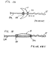
- Many distal protection devices such as the one shown in FIGS. 1A , and B utilize a filter having a distal end that slides over or along an elongate support member SM such as a guidewire.
- the filter F is shown in its expander deployed configuration in FIG. 1A and in its contracted delivery configuration in FIG. 1B .
- the distal end is at a first position with respect to the elongate support member when the filter is in its contracted delivery configuration and at a second more proximal position when the filter is in its expanded deployed configuration.
- the length of the elongate support member that extends distally of the distal end of the filter must be increased by an amount S equal to the distance between the first and second positions to accommodate the slideable distal end of the filter.
- This increased elongate support member length distal to the filter can be a disadvantage for the reasons set forth above.
- this increased elongate support member length can prevent the filter from being used in connection with the treatment or distal lesions in the vascular anatomy since placement of the filter at a location distal to the treatment site may not be possible.
- This invention is an embolic protection device or system for use in a lumen of a vessel in a patient's vascular system.
- the invention provides a protection device for use in a-body lumen comprising an elongate support member having proximal and distal ends and a stop positioned proximally of the distal end which divides the elongate support member into proximal and distal portions.
- a proximal slider is slideable over the proximal portion of the elongate support member.
- the stop limits movement of the slider in a distal direction.
- a distal slider is slideable over the distal portion of the elongate support member.
- a functional element is carried by the elongate support member, the functional element being expandable from a delivery configuration to an expanded deployed configuration when the functional element is deployed in the body lumen.
- the functional element has a proximal end and a distal end.
- the proximal end of the functional element is connected to the proximal slider.
- the distal end of the functional element is connected to the distal slider.
- the functional element has a body defining a cavity, the distal end of the elongate support member being contained within the cavity and being slideably received by the distal slider when the functional element is in the delivery configuration and when tho functional clement is in the expanded deployed configuration.
- the devices described herein include embolic filters the present invention is also applicable to other types of functional devices including occlusive devices comprising inflatable balloons or filter-like framework structures coated with flexible polymer.
- occlusive balloon device it is advantageous to construct the device on a hollow elongate member so as to allow inflation and deflation of the balloon through the hollow member.
- the examples relate generally to protection devices deployed distal to a treatment site, the device can also be deployed proximal to a treatment site for the purpose of interrupting or reversing flow through the vessel.
- a proximally deployed device it will be advantageous to construct the device on a hollow elongate member so as to preserve access to the treatment site through the hollow member.
- distal and proximal refer to the relative position of the guidewire, catheters, and distal protection system in a lumen.
- proximal refers to a location upstream from the “distal” position. That is, the flow of a body fluid, such as blood, moves from the proximal to the distal portions of the device of this invention.
- distal protection systems are meant to encompass the use of any functional device such as occlusive devices and filters designed to be deployed in a vessel of a patient in a minimally invasive procedure.
- the distal protection system is introduced into a blood vessel through an introducing catheter.
- Methods of introducing guidewires and catheters and the methods for the removal of such devices from vessels are well known in the art of endovascular procedures.
- the elongate support member and filter are loaded into an introducing sheath or catheter and moved into tho vessel and through the catheter to the treatment site. This is done typically by advancing a first, or introduction guidewire, through the vessel to the region of interest.
- a catheter is advanced over the guidewire to the region of interest, and the guidewire removed.
- the filter or other functional device carried by the elongate support member is advanced down a catheter sheath to the region of interest but within the catheter.
- the catheter sheath is withdrawn to deploy (expand) the filter at the region of interest.
- the filter is preloaded into a catheter and held in place by an outer sheath of the catheter and they are together advanced through the vessel to the region of interest without using an initial guidcwirc.
- the catheter is withdrawn to deploy the filter.
- an introduction guidewire is advanced to the region of interest, and the filter (contained in a catheter) is advanced over the guidewire to the region of interest, at which point the catheter is removed leaving the deployed filter near the region of interest on the guidewire.
- Typical dimensions of a filter used in the devices of this invention range from 2 mm to 90 mm in length, and from about 0.5 mm to 2 mm in diameter before deployment, and about 2 mm to 30 mm in diameter after deployment.
- a typical guidewire is about 0.2 to 1.0 mm diameter and ranges from 50 cm to 320 cm in length.
- the protection device is made from biocompatible materials. Materials also may be surface treated to produce biocompatibility.
- the elongate support member may be formed of any material of suitable dimension, and generally comprises metal wire. Suitable materials include stainless steel, titanium and its alloys, cobalt-chromium-nickel-molybdenum-iron alloy (commercially available under the trade designation ElgiloyTM), carbon fiber and its composites, and engineered polymers such as liquid crystal polymers, polyetheretherketone (PEEK), polyimide, polyester, and the like. A shape memory or superelastic metal such as nitinol is also suitable.
- the elongate support member may be solid or may be hollow over some or all of its length.
- the material used to make the filter or filter support structure preferably is self-expanding. This can be accomplished by using self-expanding materials. These materials include metals such as stainless steel, titanium and its alloys, cobalt-chromium-nickel-molybdenum-iron alloy (commercially available under the trade designation ElgiloyTM), carbon fiber and its composites, and engineered polymers such as liquid crystal polymers, polyetheretherketone (PEEK), polyimide, polyester, silk, and the like.
- a shape memory or superelastic metal is particularly suitable for those applications when it is desired for an element, such as a filter, to assume a pre-determined three-dimensional shape or for a guidewire, to maintain a pre-determined curvature.
- a shape memory or superelastic metal comprising nickel and titanium known as "nitinol” is commercially available in various dimensions and is suitable for use as both a guidewire and a filter.
- nitinol tubular braid can be heat set into a desired shape, compressed for delivery to a site, and then released to form the heat-set shape.
- the filter element has a body defining an interior cavity.
- the filter body has a plurality of openings such that, when the filter element is in its deployed configuration within the vessel lumen, particles within the fluid are captured inside the interior cavity of the filter element.
- the filter may comprise any material that is suitably flexible and resilient, such as a mesh, i.e., a material having openings or pores.
- the filter may comprise braided, knitted, woven, or non-woven fabrics that are capable of filtering particles having dimension of 40 to about 500 microns. Non-woven fabrics may additionally be treated to fuse some or all of the fiber intersection.
- the fabric may be electrospun.
- Suitable material includes that formed from sheets, films, or sponges, polymeric or metallic, with holes formed by mechanical means such as laser drilling and punching, or by chemical means such as selective dissolution of one or more components.
- a suitable filter material is braided tubular fabric comprising superelastic nitinol metal. Mesh fabric of nitinol materials can be heat-set to a desired shape in its expanded configuration.
- the filter material is preferably at least partially radiopaque.
- the filter material can be made radiopaque by plating, or by using core wires, tracer wires, or fillers that have good X-ray absorption characteristics compared to the human body.
- the device includes a sliding element, for example, at the proximal end of the filter.
- sliding element comprises inner and outer annular rings. To first ring fits within the second ring. The inner diameter of the first ring is larger than the diameter of the elongate support member so that the sliding element can slide over the elongate support member.
- the sliding element can be affixed to the filter fabric by placing the fabric between the first and second rings. However, this is not meant to be limiting, and the filter fabric can also be affixed to the slidcable element by adhesive, solder, crimping, or other means known in the art.
- the slider may comprise stiff material such as metal or polymer and preferably the slider is radiopaque. Suitable materials include stainless steel, titanium, platinum, platinum/iridium alloy, gold alloy, polyimide, polyester, polyetheretherketone (PEEK), and the like.
- Movement of a sliding element with respect to the elongate support member can be facilitated by coating one or both of the inside of the sliding element and the outside of the elongate support member with a friction-reduciug coating, such as polytetrafluoroethylene (commercially available under the trade designation TeflonTM) or a lubricious hydrophilic coating.
- a friction-reduciug coating such as polytetrafluoroethylene (commercially available under the trade designation TeflonTM) or a lubricious hydrophilic coating.
- fixed element is meant an element that is attached to the elongate support member and does not move independently of it.
- the fixed element may be an annular ring but also included within this meaning is an element that is crimped, adhered, soldered, or otherwise fastened directly to the elongate support member.
- the filter fabric may be attached directly to the elongate support member.
- the sliding and fixed elements typically comprise radiopaque material to assist in the placement of the filter.
- one or more radiopaque markers may be positioned at various locations on the protection device. These radiopaque markers or marker bands comprise a material that will be visible to X-rays and they assist in positioning the device.
- Some embodiments include a "floppy tip" at a distal portion of the distal elongate support segment.
- the floppy tip provides an atraumatic and radiopaque terminus for the device.
- An atraumatic tip prevents vessel injury during initial placement or subsequent advancement of the device.
- a radiopaque tip helps the physician verify suitable tip placement during fluoroscopy.
- the floppy tip preferably comprises a springy or resilient materials, such as a metal (e.g., stainless steel, iron alloys such as Elgiloy TM , and shape memory or superelastic metal such as nitinol) or polymer (e.g., polyetheretherketone (PEEK), polyimide, polyester, polytetratluoroethylene (PTFE), and the like).
- PEEK polyetheretherketone
- PTFE polytetratluoroethylene
- Springy materials are desirable because they tend to retain their shape. The physician will initially 'shape' the tip, typically with a slight curve, and then as the device is advanced through the body the tip will be deflected as it encounters obstacles. It is desirable, after the inevitable deflections during insertion, that the tip restore itself to the pre set shape.
- Polymeric materials additionally may be reinforced with metals or other fillers.
- the material may be a monofilament or multifilament (such as a cable).
- the floppy tip may be tapered or have a uniform diameter over its length.
- the floppy tip may comprise a tube, or could have circular, flat, or other cross-sections. It may be coiled.
- the tip may comprise one or more elements (i.e., parallel independent structures).
- the tip may be polymer-coated or otherwise treated to make the surface slippery.
- the floppy tip can be any desired length.
- Other elements of the filtration device also comprise biocompatible materials, and these include metals and polymeric materials. These materials can be treated to impart biocompatibility by various surface treatments, as known in the art.
- the wire is selected on the basis of the characteristic desired, i.e., stiffness or flexibility, and the properties can depend upon both the diameter of the wire and its cross-sectional shape.
- the size, thickness and composition of elastic materials are selected for their ability to perform as desired as well as their biocompatibility. It is to be understood shat these design elements are all within the scope of this invention.
- FIGS. 1A and 1B are schematic views of a prior art distal protection device having an elongate support member SM which carries a filter F.
- the proximal end of the filter is connected to a proximal fixed element PF and the distal end of the filter is connected to a distal slider DS.
- the proximal fixed element is connected at a fixed location on the elongate support member while the distal slider is configured to slide freely over the elongate support member.
- the elongate support member terminates distally at atraumatic floppy tip T.
- the filter is shown in its expanded deployed configuration in FIG. 1A and in its contracted delivery configuration in FIG. 1B . As best seen in FIG. 1A the distal slider travels over the elongate support member a distance S when the filter is contracted from the deployed to the delivery configuration.
- An example of such a filter is disclosed in WO 96/01591 (Mazzochi et al. ).
- FIGS. 2 to 15 are schematic views of various examples of a device which includes a discontinuous elongate support member carrying a functional element such as a filter or occlusive device.
- the elongate support member includes a proximal elongate support segment and a distal elongate support segment.
- the functional element has a proximal end connected at or near a distal end of the proximal elongate support segment and a distal end connected at or near a proximal end of the distal elongate support segment.
- the functional element has a body which defines an interior cavity. No substantial portion of the elongate support member lies within the cavity.
- the protection device is constructed so that the functional element expands from its delivery configuration to its deployed configuration without interference between the distal and proximal elongate support elements. Specifically, when the functional element is deployed the distance between the distal and proximal ends of the functional element decreases. In most examples, but not necessarily all examples, when the functional element is fully expanded there is still distance between the distal and proximal ends of the element.
- this design permits some portion of the distal and/or proximal elongate support members to be within the cavity so long as the length or combined lengths of the portion(s) within the cavity do not exceed the distance between the distal and proximal ends of the functional element in its fully expanded configuration and thus there is no interference with the expansion and deployment of the functional element.
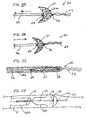
- FIGS. 2A and 2B show. filter 21 affixed to proximal fixed element 24 which is affixed to the distal end of proximal elongate support segment 22.
- Filter 21 has distal element 26 which is affixed to a distal elongate support segment including floppy tip 23.
- Floppy tip 23 is provided as an atraumatic terminus for the filter.
- Floppy tip 23 may optionally be radiopaque.
- the tip comprises any suitably flexible and springy material, as discussed above.
- Mesh 21a is indicated by cross-hatching in the figure. Both figures illustrate a deployed filter, but comparison of FIGS.
- FIGS. 1A and 2B show how the filter shape changes and mesh 21a compresses when the proximal elongate support segment is moved distally relative to distal element 26 along the direction shown by the arrow in FIG. 2B . Comparing FIGS. 1A and 2A it is apparent that the distal elongate support segment 23 need not include the additional length S since distal element 26 is not required to slide over the elongate support member.
- FIG. 2C shows the filter of FIGS. 2A and 2B in its contracted delivery configuration contained in a delivery catheter 500.
- FIGS. 2A to 2C clearly show that although the distance between elements 24 and 26 varies from the delivery to the deployed configuration the distance between the distal element and the distal tip of the distal elongate support segment does not vary but remains constant at all times during the delivery and deployment of the filter. Thus, no additional length need be provided for the elongate support member extending distal to the filter to accommodate the differences in the distance between the proximal and distal elements.
- the catheter is advanced through a body lumen such as the lumen of a vessel until the filter is positioned at a desired location distal to a treatment site in the lumen. Positioning of the filter is facilitated by the floppy tip portion of the distal guidewire segment which allows the catheter to be maneuvered through even tortuous lumens. However, the distal segment is not required to be made longer than necessary or desired for efficient maneuverability.
- the filter is deployed by withdrawing catheter 500 proximally to expose the self-expanding filter.
- the gap between the proximal end of the distal elongate support segment and the distal end of the proximal elongate support segment closes. The gap is closed by movement of the distal elongate support segment in a proximal direction caused by the expansion of the filter and/or by the physician moving the proximal elongate support segment in a distal direction.
- FIG. 2D shows a recovery system that could be used to remove a distal protection device such as the one shown in FIGS. 2A to 2C from a body lumen.
- System 30 includes a recovery catheter 600 and a funnel or cover 510.
- the catheter 600 is advanced over the proximal elongate support segment toward the filter which has been used to capture emboli or other debris E during a treatment procedure in the lumen of a vessel V.
- the cover is contained within the lumen of the recovery catheter.
- the cover At a desired location just proximal of the filter the cover is deployed by withdrawing the recovery catheter distally.
- the filter is then pulled into the cover by withdrawing the proximal elongate support segment proximally.
- the filter may retain its general bell shape or may revert somewhat into an olive shape.
- the captured emboli is retained because the self-expanding filter will maintain enough of an expanded shape against the walls of the body lumen to retain the emboli
- the cover and filter are withdrawn into the recovery catheter and the recovery catheter, cover and filter are withdrawn from the body lumen.
- the cover assists in retaining emboli within the filter during the withdrawal process.
- the recovery catheter and cover are described more fully in WO 00/53120 (Kusleika et al ).
- a similar elongate support member design can be incorporated into a variety of other embolic protection devices.
- the design can be incorporated into protection devices having elongate support members or filters of varying configuration.
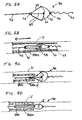
- proximal face 31a of the filter may be provided with larger filter holes than the distal face 31b of the filter.
- the proximal face can be made of a mesh or other material with holes of sufficient size to enable emboli to flow into the filter between the proximal and distal faces and the distal face can be totally or partially occlusive such as by way of an occlusive coating or attached film. In either case this enables emboli to be aspirated into the tube and out of the lumen in the direction of the arrows in FIG. 3B .
- FIGS. 3A and 3B could be constructed with a filter like the one disclosed in FIG. 12A .
- FIG. 3C Such a configuration is shown in FIG. 3C , in which filter 31 is shown with two wire segments or loops 39. These loops or segments attach to the proximal end of the filter and serve to bias the filter and its opening 35 in its open or expanded configuration. The loops also serve to stabilize proximal element 34 against the lumen wall so as the prevent emboli from bypassing the filter due to motion of proximal elongate support segment 32.
- FIGS. 4 to 10 illustrate various examples of the device wherein the filter comprises struts which assist in holding the filter mesh open and/or in collapsing the filter into a recovery catheter.
- FIG. 4A shows device 40, in which the proximal end of filter 41 is affixed to proximal fixed element 44.
- Element 44 is affixed to proximal elongate support segment 42.
- the distal end of filter 41 is attached to distal element 46 to which is attached a distal elongate support segment including floppy tip 43.
- Filter element 41 is biased to self-expand and is shown in its expanded deployed configuration in FIG. 4A .
- Extending proximally from filter 41 are struts or tethers 49 which are affixed at one end to element 45.
- Element 45 is affixed to proximal guidewire segment 42 at a point proximal of element 44.
- the tethers are connected at their second end to a peripheral lip of filter 41 by welding, knotting interweaving, traversing between the mesh layers, and the like.
- the struts or tethers permit recovery of the filter from a body lumen without the use of a separate funnel or cover.
- FIG. 4B illustrates device 40 within a delivery catheter 500.
- the device is loaded into the catheter by pulling the proximal elongate support segment proximally ion the direction of the arrow until the filter is contained within the lumen of the delivery catheter.
- the device is used by advancing the deliver catheter through a body lumen until the distal end of the delivery catheter is at a desired location distal to the treatment site.
- the filter is then deployed in the body lumen. This can be done by withdrawing the delivery catheter proximally while maintaining the position of the filter or by advancing the filter distally while maintaining the position of the delivery catheter by advancing the proximal elongate support segment distally.
- FIGS. 4C and 4D illustrate one way in which filter 41 may be recovered from the body lumen after capturing emboli E released during a treatment procedure.
- the device can be recovered with the same catheter used to deliver the device or with a separate recovery catheter 450 which is usually slightly larger than the delivery catheter.
- the recovery catheter is advanced over the proximal elongate support segment. Once the distal end of the recovery catheter has been advanced distally of element 45 the tethers 49 are drawn into lumen 450a of the recovery catheter. This causes the peripheral lip of the filter to be drawn radially inwardly in the direction of the proximal elongate support segment. In FIG. 4C the peripheral lip is shown partially closed. In FIG.
- the delivery catheter is shown advanced to a more distal position and the peripheral lip is drawn up to the distal end of the recovery catheter. It is possible to withdraw the recovery catheter, elongate support member and filter in the configuration shown in FIG. 4D or, alternatively, the delivery catheter may be advanced distally until the filter is contained entirely or partially within the delivery catheter before it is withdrawn from the body lumen.
- FIGS. 5A, 5B and 5C illustrate a device 50, similar to device 40, except that the tethers are connected at their proximal ends to a hollow tube which is moveable axially with respect to the elongate support member.
- Filer 51 is biased to self-expand and is affixed at its proximal end to proximal fixed element 54 which in turn is affixed to proximal elongate support segment 57.
- Filter 51 has distal element 56 that is attached to a distal elongate support segment including floppy tip 53.
- Extending proximally from a peripheral lip of filter 51 are struts or tethers 59 which are affixed at one end to the filter and at another end to element 55.
- Element 55 is affixed to hollow tube 52.
- FIG. 5A shows the device in its expanded deployed configuration with the tube positioned with respect to the proximal elongate support segment so that there is no slack in the tethers.
- FIG. 5B shows the device in its deployed configuration but with the tube advanced distally so that there is slack in the tethers.
- FIG. 5C shows the device loaded in a delivery catheter 500. When loaded in the delivery catheter the tube may be positioned so the tethers arc slack or so there is no slack in the tethers. The device is used by advancing the delivery catheter to a desired location distal to the treatment site. The delivery catheter is withdrawn proximally while the tube and proximal elongate support segment are held stationery to deploy the filter.
- the tube can be withdrawn a short distance proximally to remove any slack from the tethers.
- the filter is removed in a manner somewhat similar to that described with respect to FIG. 4 .
- any slack in the tethers is removed by moving the tube proximally.
- the delivery catheter or a separate larger recovery catheter is advanced distally over the proximal elongate support segment while the position of the tube and the proximal elongate support segment are maintained. In this manner the filter is drawn into the recovery catheter in the same manner as described above.
- FIG. 6 illustrates device 60, wherein filter 61 comprises coiled strut 69, a distal portion of which is covered by filter fabric 61a (shown by cross-hatching).
- filter fabric 61a shown by cross-hatching
- material 61a could be occlusive.
- Strut 69 is suitably elastic such that it will self-expand to contact the wall of a vessel after deployment of the filter from the distal end of a delivery catheter.
- Strut 69 is affixed to proximal fixed element 64 which in turn is affixed to proximal elongate support segment 62.
- Filter fabric 61a is attached to a portion of strut 69 and at least strut 69 is attached distally at distal element 66 which is attached to a distal elongate support segment including floppy tip 63.
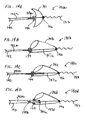
- FIG. 7 illustrates device 70 which includes multiple struts 79 having an angular shape.
- Four struts are shown in the figure although more or fewer could be used.
- two of the struts are in the plane of the page; two are perpendicular to the plane of the page, one extending toward the viewer and the other extending away.
- Struts are biased to expand into contact with a lumen wall.
- Struts 79 are affixed to proximal and distal elements 74 and 76.
- Proximal element 74 is fixed to proximal elongate support segment 72.
- Distal element 76 is fixed to a distal elongate support element including floppy tip 73.
- a distal portion of struts 79 is covered with filter fabric or filtering polymer film 71a (shown by cross-hatching).
- FIG. 8 illustrates device 80, which has a structure similar to the devices shown in FIGS. 6 and 7 .
- Multiple self-expanding curvilinear struts 89 (4 struts are shown in the figure although more or fewer could be used) are affixed to proximal and distal elements 84 and 86.
- Proximal element 84 is fixed to elongate support member 82.
- Distal element 86 is fixed to a distal elongate support segment including floppy tip 83.
- a distal portion of struts 89 is covered with filter fabric or filtering polymeric film 81a (shown by cross-hatching).
- Optional marker bands 85 are shown on two of the struts, near the edge of the filter fabric. Such bands assist in proper placement of the filter.
- FIG. 9 illustrates device 90, similar to devices described for FIGS. 6 to 8 .
- Multiple struts 99 having a sinusoidal shape (4 struts are shown in the figure although more or fewer could be used) are affixed to proximal and distal elements 94 and 96.
- Proximal element 94 is fixed to proximal elongate support segment 92.
- Distal element 96 is fixed to a distal elongate support segment including floppy tip 93.
- a distal portion of struts 99 is covered with filter fabric or filtering polymeric film 91a (shown by cross-hatching).
- FIG. 10 illustrates device 100, similar to devices described in FIGS. 6 to 9 .
- Multiple struts 109 (3 struts are shown in the figure although more or fewer could be used) are affixed to proximal and distal element 104. Additional struts 109a arc provided in the distal portion and are affixed to distal element 106.
- a segmented circumferential ring 109b is provided in which struts 109 and 109a are attached.
- Proximal element 104 is fixed to proximal elongate support segment 102.
- Distal element 106 is fixed to a distal elongate support segment including floppy tip 103.
- a distal portion of filter 101 is covered with filter fabric or filtering polymeric film 101a (shown by cross-hatching).
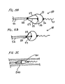
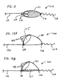
- FIG. 11 shows fitter device 110 comprising self-expanding filter 111 having proximal fixed element 114 which is fixed to proximal elongate support segment 112 and distal fixed element 116 which is fixed to a distal elongate support segment including floppy tip 113.
- Filter 111 is provided with at least one proximally facing entry hole 119. Two holes 119 are shown in the future. When filter 111 is deployed in a body lumen, fluid flows into the filter through holes 119.
- the holes in the filter mesh are sufficiently sized to allow the emboli containing fluid to pass through the filter and to trap and retain any emboli or debris within the filter while allowing the fluid to pass therethrough.
- FIG. 12A shows filter device 120, wherein filter device 120 comprises self-expanding filter 121 with distal element 126 affixed to a distal elongate support segment including floppy tip 123.
- Wire segment 129 extends from fixed proximal element 124 and forms a loop which attaches to the proximal end of the filter and serves to bias the filter and its proximally facing opening 125 in their open or expanded configuration.
- Wire segment 129 also serves to stabilize proximal element 124 against the lumen wall so as the prevent emboli from bypassing the filter due to motion of wire 122.
- proximal wire loops are more fully described in EP 1 181900 A2 .
- Filter 121 is attached proximally at fixed element 124 which in turn is affixed to proximal elongate support segment 122.
- FIG. 12B shows a device similar to that of FIG. 12A except that a flexible coil 127 is attached between proximal and distal elements 124 and 126.
- the coil serves as a safety wire when fully extended as when the device is being withdrawn proximally during retrieval.
- the coil also serves to provide transverse flexibility in the region of the filter so as to avoid vessel straightening which is commonly observed in the prior art by the use of straight wires within the filter.
- the coil could be a braid or series of wire bends that are not coiled.
- the coil could be an elastomeric polymer or a straight piece of solid or tubular elastomer or could be any other construction having the properties of a coil or elastomer.
- FIGS. 13A to 13C show a filter device similar to a device described in WO 01/87183 (entitled “Emboli Filter” to Blackledge et al.) with the exception that the elongate support member has been made discontinuous.
- Filter device 130 comprises filter 131 having a conical shape. At its proximal end, the periphery of the filter is attached to elongate member 132 by means of circumferentitally spaced elastic loops 134 having a cloverleaf shape.
- these elastic loops comprise nitinol. They are biased to open radially outwardly, thus serving to hold open the filter.
- FIG. 13B more clearly illustrates secondary loops 134b that provide a convenient attachment point to the filter.
- the loops are shown sutured (at suture point 134a) to the filter or may be attached by any suitable method.
- the present device has a guidewire or elongate member that terminates at the proximal end of the filter, so that no guidewire extends through the filter.
- the filter has conical tip 136 that is attached to a distal elongate support segment 133.
- the filter device is shown with hollow tube 135 into which the filter can be retracted for either delivery or removal.
- FIG. 13C shows a cross-sectional view of an alternative filter device 130 attached to elongate member 132 (shown in phantom), in body lumen A.
- the filter device is manipulated by handle 138.
- loops 134o are of a different shape and the distal ends of the loops are secured via attachment element 137 to the distal end of guidewire 132.
- the proximal ends of the loops am attached to guidewire 132 at point 132a.
- Flexible tie strings 139 are attached to filter 131 and to guidewire 132. The tie strings serve to close the filter as the guidewire is being moved proximally, that is, during withdrawal of the filter.
- FIGS. 14A to 14D show various distal protection devices wherein the discontinuous elongate support member includes a distal elongate support segment telescoped within the lumen of a proximal elongate support segment.
- FIG. 14A shows filter device 140a in which filter 141 is attached to proximal fixed element 144 at proximal elongate support segment 142, which is hollow.
- Received within lumen 142a of the proximal elongate support segment is a second, smaller diameter wire 147a, which comprises a distal elongate support segment and which extends from within the lumen of the proximal support segment to distal element 146, also attached to the filter which includes floppy tip 143.
- Second wire 147a can "telescope" into proximal elongate support segment 142, thus providing for movement of the distal end of the filter but without requiring additional length of the elongate support member as in the prior art device shown in FIG. 1A and B .
- FIG. 14B shows a design similar to FIG. 14A but as applied to a windsock shaped filter 141b.
- narrow diameter wire 147b extends from the distal element 146 past the proximal element 144 and into lumen 142a of proximal elongate support member 142.
- FIG. 14C is an example similar to FIG. 14B where the proximal elongate support member 142 extends into the filter and narrow diameter wire 147c extends through lumen 142a from the distal element past the proximal element
- FIG. 14D is similar to the example of FIG.
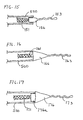
- FIGS. 15 to 17 illustrate various distal tip configurations for the distal end of the filters shown in the previous examples. These figures show alternative views of the devices when they are loaded into a delivery catheter before deployment or, alternatively, retrieved by a catheter after they have been used. It is to be understood that these configurations may be used with any of the above-described examples.
- FIG. 15 illustrates distal element 156 having floppy tip 153 extending from it.
- Element 156 is attached to the distal end of filter 151.
- Distal element 156 has a dimension that allows it to enter catheter 500. Its distal portion is tapered, and preferably its proximal edge is chamfered. The advantage of this : is that the protection device can traverse through the lumen of the catheter smoothly, without snagging or hanging up.
- distal element 166 has floppy tip 163 extending from it. Element 166 is attached to the distal end of filter 161. Distal element 166 is larger than, catheter 500, and is tapered for ease of movement into a vessel.
- distal element 166 provides a smooth transition between the outside diameter of floppy tip 163 and the outside diameter of catheter 500.
- FIG. 17 shows distal element 176 having floppy tip 173 extending from it. Element 176 "steps down" at element 176a, which is attached to the distal end of filter 171. Distal element 176a can enter catheter 500 while element 176 cannot. This configuration assures good coaxial alignment between catheter 500 and distal element 176 so that the benefits described in connection with FIG. 16 can be realized in vessel bends or tortuosity.
- a distal protection device has an elongate support member which carries a functional element such as a filter.
- the elongate support member is continuous and has a distal portion to which the proximal end of the filter is attached, either fixedly or slidingly.
- the elongate support member has a distal end which is located proximally of the distal end of the filter at all times during delivery, deployment, use and retrieval of the device. No portion of the elongate support member extends distally of the distal end of the filter.
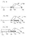
- FIG. 18 shows device 180 which includes self-expanding filter 181 carried by a continuous elongate support member 182.
- the filter has a distal end connected to a fixed distal element 186.
- Fixed distal element 186 is shaped so that it is atraumatic and is preferably radiopaque.
- Sliding proximal element 184 is connected to the filter.
- Elongate support member 182 has an enlarged distal end 185 that cannot pass through proximal element 184 and that cannot pass through mesh 181, to ensure that the filter 181 does not become detached from elongate support member 182 during use, and to prevent the enlarged distal end from passing through or puncturing filter 181.
- the continuous elongate support member feature disclosed in FIGS. 18-20 in any of the devices of FIGS. 2 to 14 .
- the elongate support member would include only what is disclosed in those figures as the proximal elongate support segment and that no portion of the elongate support member would extend distally of the distal end of the functional element Devices so constructed can be deployed very distally, for example in native coronary arteries.
- Very distal deployment of a protection device allows embolic protection of distal lesions during treatment. Distal lesions cannot be treated with prior art devices because their long wire tips impinge on the small diameter vessels thereby preventing very distal advancement and deployment of prior art devices.
- FIGS. 19A to 19C show the elongate support member being continuous and having a distal end that moves over a range of motion between proximal and distal ends of a functional device.
- the device includes self-expanding filter 191 which is affixed to proximal slider element 194.
- Proximal element 194 acts as a marker band and also slides freely over elongate support member 192.
- Distal element/marker 196 is located at the distal end of filter 191.
- Elongate support member 192 extends into the filter and terminates at stop 195, which comprises elongate portion 195a and ball tip 195b that is larger than any spaces in the filter mesh. Thus stop 195 cannot move from inside the filter.
- FIG. 19B illustrates back-loading the device into catheter 500.
- Elongate support member 192 is withdrawn proximally until stop 195 engages proximal element 194. Further proximal advancement of elongate support member 192 pulls proximal element, stop, and mesh 191 into catheter. The mesh collapses around stop 195 and ball tip 195b as it is withdrawn into catheter 500. Further proximal withdrawal of elongate support member 192 collapses mesh 191 into the catheter.
- FIG. 19C shows the distal protection device loaded inside catheter 500 and ready for deployment
- the device is used by advancing the delivery catheter through a body lumen until ths distal end of the delivery catheter is at a desired location distal to the treatment site.
- the filter is then deployed in the body lumen. This can be done by withdrawing the delivery catheter proximally while maintaining the position of the filter or by advancing the filter distally while maintaining the position of the delivery catheter by advancing the elongate support member 192 distally.
- the elongate support member 192 is advanced relative to the filter 191, the ball tip 195b will advance distally until contact with the distal end of filter 191 and the distal element 196 is achieved. At this point further advancement of elongate support member 192 relative to filter 191 will urge device 190 out the end of catheter 500.
- Filter 191 will self-expand into contact with the luminal wall as it is released from catheter 500. In this position emboli and fluid will enter the opening of filter 191. Emboli will be retained in the filter while fluid will pass therethrough. The filter will resist axial or rotational motion of wire 192 because proximal element 194 slides freely over elongate support member 192. Device 190 with emboli contained therein can be recovered by advancing a catheter over elongate support member 192 and withdrawing the elongate support member relative to the filter such that at least the opening of filter 191 is collapsed within the catheter.
- the catheter can be either the catheter used to deliver the device to the treatment site, a specially designed recovery catheter that may be larger in diameter than the delivery catheter, a treatment catheter such as a PTCA catheter or the like, or another catheter.
- a specially designed recovery catheter that may be larger in diameter than the delivery catheter
- a treatment catheter such as a PTCA catheter or the like
- another catheter Once at least the opening of filter 191 is collapsed within a catheter, the catheter can be withdraw proximally and out of the body.
- FIG. 20 shows a device in accordance with the claimed invention having a filter device wherein the elongate support member is provided with a distal slider element, such as a hypotube or more preferably a tight wound coil.
- Filter device 200 comprises filter 201 having proximal sliding element 204 and distal element 207.
- Slider element 204 slides freely over elongate support member 202 which extends into filter 201.
- Stop 205 such as a wire coil or a hypotube, is affixed to the elongate support member within the filter.
- Distal slider 207 is configured to accept the distal portion of the elongate support member. Stop 205 and slider 207 are positioned such that the distal end of the elongate support member is always contained within slider 207.
- Distal slider 207 may be a coil of wire or a hypotube. Distal slider 207 ensures that the filter will be securely carried by the elongate support member while at the same time allowing the filter to move longitudinally and rotate axially with respect to the elongate support member.
- FIGS. 18 , 19A to 19C , and 20 are shown with a continuous elongate support member and have no distal floppy tip, it should be appreciated that these embodiments could be constructed to include a floppy tip such as shown in FIGS. 2 to 17 .
- the protection device of this invention is particularly useful in the prevention of distal embolization of debris liberated during interventional procedures such as in cardiology, radiology, and neuroradiology procedures.
Landscapes
- Health & Medical Sciences (AREA)
- Life Sciences & Earth Sciences (AREA)
- Veterinary Medicine (AREA)
- Engineering & Computer Science (AREA)
- Biomedical Technology (AREA)
- Heart & Thoracic Surgery (AREA)
- Surgery (AREA)
- Animal Behavior & Ethology (AREA)
- General Health & Medical Sciences (AREA)
- Public Health (AREA)
- Vascular Medicine (AREA)
- Nuclear Medicine, Radiotherapy & Molecular Imaging (AREA)
- Medical Informatics (AREA)
- Molecular Biology (AREA)
- Anesthesiology (AREA)
- Transplantation (AREA)
- Reproductive Health (AREA)
- Orthopedic Medicine & Surgery (AREA)
- Biophysics (AREA)
- Pulmonology (AREA)
- Cardiology (AREA)
- Hematology (AREA)
- Oral & Maxillofacial Surgery (AREA)
- Surgical Instruments (AREA)
- Medicines Containing Antibodies Or Antigens For Use As Internal Diagnostic Agents (AREA)
- Pharmaceuticals Containing Other Organic And Inorganic Compounds (AREA)
- Agricultural Chemicals And Associated Chemicals (AREA)
Claims (4)
- Schutzvorrichtung (200) zur Verwendung in einem Körperlumen, die Folgendes umfasst:ein längliches Trägerelement (202) mit einem proximalen länglichen Segment und einem distalen länglichen Segment, wobei das proximale und das distale längliche Segment jeweils ein proximales und ein distales Ende haben, wobei das distale Ende (205) des proximalen länglichen Segments vergrößert ist,ein proximales Gleitelement (104), das über das proximale längliche Segment verschiebbar ist, wobei das vergrößerte distale Ende (205) des proximalen länglichen Segments die Bewegung des proximalen Gleitelements (204) in einer distalen Richtung begrenzt,ein distales Gleitstück (207), das über das distale längliche Segment verschiebbar ist,ein Funktionselement (201), das von dem länglichen Trägerelement (202) getragen wird, wobei das Funktionselement von einer Einbringungskonfiguration auf eine ausgedehnte gesetzte Konfiguration ausdehnbar ist, wenn das Funktionselement (201) in dem Körperlumen gesetzt wird, wobei das Funktionselement (201) ein proximales Ende und ein distales Ende hat, wobei das proximale Ende des Funktionselements mit dem proximalen Gleitelement (204) verbunden ist, wobei das Funktionselement einen Körper hat, der einen Hohlraum definiert, wobei das vergrößerte distale Ende (205) des proximalen länglichen Segments in dem Hohlraum enthalten ist, und das distale Ende (206) des Funktionselements (201) mit dem distalen Gleitstück (207) verbunden ist, wobei das distale Ende des distalen länglichen Segments in dem Hohlraum enthalten ist und verschiebbar von dem distalen Gleitstück (207) aufgenommen wird, wenn das Funktionselement (201) in der Einbringungskonfiguration ist und wenn das Funktionselement (201) in der ausgedehnten gesetzten Konfiguration ist.
- Schutzvorrichtung nach Anspruch 1, bei der das Funktionselement ein Filter umfasst.
- Schutzvorrichtung nach Anspruch 1, bei der das Funktionselement ein okklusives Element umfasst.
- Schutzvorrichtung nach Anspruch 3, bei der das okklusive Element einen Ballon umfasst.
Priority Applications (1)
| Application Number | Priority Date | Filing Date | Title |
|---|---|---|---|
| EP11163492.9A EP2361590B1 (de) | 2002-04-25 | 2003-04-25 | Vaskulare Schutzvorrichtungen und Verfahren zu deren Benutzung |
Applications Claiming Priority (3)
| Application Number | Priority Date | Filing Date | Title |
|---|---|---|---|
| US132562 | 1980-03-21 | ||
| US10/132,562 US7192434B2 (en) | 2002-03-08 | 2002-04-25 | Vascular protection devices and methods of use |
| PCT/US2003/013061 WO2003090607A2 (en) | 2002-04-25 | 2003-04-25 | Vascular protection devices and methods of use |
Related Child Applications (2)
| Application Number | Title | Priority Date | Filing Date |
|---|---|---|---|
| EP11163492.9A Division EP2361590B1 (de) | 2002-04-25 | 2003-04-25 | Vaskulare Schutzvorrichtungen und Verfahren zu deren Benutzung |
| EP11163492.9 Division-Into | 2011-04-21 |
Publications (2)
| Publication Number | Publication Date |
|---|---|
| EP1501401A2 EP1501401A2 (de) | 2005-02-02 |
| EP1501401B1 true EP1501401B1 (de) | 2011-08-17 |
Family
ID=29268760
Family Applications (2)
| Application Number | Title | Priority Date | Filing Date |
|---|---|---|---|
| EP11163492.9A Expired - Lifetime EP2361590B1 (de) | 2002-04-25 | 2003-04-25 | Vaskulare Schutzvorrichtungen und Verfahren zu deren Benutzung |
| EP03721893A Expired - Lifetime EP1501401B1 (de) | 2002-04-25 | 2003-04-25 | Vaskulare Schutzvorrichtung für Blut |
Family Applications Before (1)
| Application Number | Title | Priority Date | Filing Date |
|---|---|---|---|
| EP11163492.9A Expired - Lifetime EP2361590B1 (de) | 2002-04-25 | 2003-04-25 | Vaskulare Schutzvorrichtungen und Verfahren zu deren Benutzung |
Country Status (6)
| Country | Link |
|---|---|
| US (2) | US7192434B2 (de) |
| EP (2) | EP2361590B1 (de) |
| AT (1) | ATE520336T1 (de) |
| AU (1) | AU2003225179A1 (de) |
| ES (1) | ES2372741T3 (de) |
| WO (1) | WO2003090607A2 (de) |
Families Citing this family (204)
| Publication number | Priority date | Publication date | Assignee | Title |
|---|---|---|---|---|
| EP1695673A3 (de) | 1994-07-08 | 2009-07-08 | ev3 Inc. | Intravaskulärer Filter |
| DE19882777T1 (de) | 1997-11-07 | 2000-10-26 | Salviac Ltd | Embolieschutzgerät |
| US7491216B2 (en) | 1997-11-07 | 2009-02-17 | Salviac Limited | Filter element with retractable guidewire tip |
| US7314477B1 (en) | 1998-09-25 | 2008-01-01 | C.R. Bard Inc. | Removable embolus blood clot filter and filter delivery unit |
| US6918921B2 (en) | 1999-05-07 | 2005-07-19 | Salviac Limited | Support frame for an embolic protection device |
| AU3844499A (en) | 1999-05-07 | 2000-11-21 | Salviac Limited | Improved filter element for embolic protection device |
| US6964672B2 (en) | 1999-05-07 | 2005-11-15 | Salviac Limited | Support frame for an embolic protection device |
| US7014647B2 (en) | 1999-05-07 | 2006-03-21 | Salviac Limited | Support frame for an embolic protection device |
| JP4298949B2 (ja) | 1999-08-27 | 2009-07-22 | イーブイ3 インコーポレイテッド | スライド可能な管フィルタ |
| US6325815B1 (en) * | 1999-09-21 | 2001-12-04 | Microvena Corporation | Temporary vascular filter |
| US6575997B1 (en) | 1999-12-23 | 2003-06-10 | Endovascular Technologies, Inc. | Embolic basket |
| US6402771B1 (en) | 1999-12-23 | 2002-06-11 | Guidant Endovascular Solutions | Snare |
| US6660021B1 (en) | 1999-12-23 | 2003-12-09 | Advanced Cardiovascular Systems, Inc. | Intravascular device and system |
| US6540722B1 (en) | 1999-12-30 | 2003-04-01 | Advanced Cardiovascular Systems, Inc. | Embolic protection devices |
| US7918820B2 (en) | 1999-12-30 | 2011-04-05 | Advanced Cardiovascular Systems, Inc. | Device for, and method of, blocking emboli in vessels such as blood arteries |
| US6695813B1 (en) | 1999-12-30 | 2004-02-24 | Advanced Cardiovascular Systems, Inc. | Embolic protection devices |
| GB2369575A (en) | 2000-04-20 | 2002-06-05 | Salviac Ltd | An embolic protection system |
| US7727242B2 (en) * | 2000-06-29 | 2010-06-01 | Concentric Medical, Inc. | Systems, methods and devices for removing obstructions from a blood vessel |
| US6964670B1 (en) | 2000-07-13 | 2005-11-15 | Advanced Cardiovascular Systems, Inc. | Embolic protection guide wire |
| US6537294B1 (en) | 2000-10-17 | 2003-03-25 | Advanced Cardiovascular Systems, Inc. | Delivery systems for embolic filter devices |
| US6893451B2 (en) | 2000-11-09 | 2005-05-17 | Advanced Cardiovascular Systems, Inc. | Apparatus for capturing objects beyond an operative site utilizing a capture device delivered on a medical guide wire |
| US6506203B1 (en) | 2000-12-19 | 2003-01-14 | Advanced Cardiovascular Systems, Inc. | Low profile sheathless embolic protection system |
| US7604612B2 (en) | 2001-05-01 | 2009-10-20 | St. Jude Medical, Cardiology Division, Inc. | Emboli protection devices and related methods of use |
| US7374560B2 (en) | 2001-05-01 | 2008-05-20 | St. Jude Medical, Cardiology Division, Inc. | Emboli protection devices and related methods of use |
| US7422579B2 (en) | 2001-05-01 | 2008-09-09 | St. Jude Medical Cardiology Divison, Inc. | Emboli protection devices and related methods of use |
| US7338510B2 (en) | 2001-06-29 | 2008-03-04 | Advanced Cardiovascular Systems, Inc. | Variable thickness embolic filtering devices and method of manufacturing the same |
| US6599307B1 (en) | 2001-06-29 | 2003-07-29 | Advanced Cardiovascular Systems, Inc. | Filter device for embolic protection systems |
| US6638294B1 (en) | 2001-08-30 | 2003-10-28 | Advanced Cardiovascular Systems, Inc. | Self furling umbrella frame for carotid filter |
| US6592606B2 (en) | 2001-08-31 | 2003-07-15 | Advanced Cardiovascular Systems, Inc. | Hinged short cage for an embolic protection device |
| US8262689B2 (en) | 2001-09-28 | 2012-09-11 | Advanced Cardiovascular Systems, Inc. | Embolic filtering devices |
| EP1455681B1 (de) | 2001-12-21 | 2014-09-17 | Salviac Limited | Stützrahmen für eine embolieschutzvorrichtung |
| US7241304B2 (en) | 2001-12-21 | 2007-07-10 | Advanced Cardiovascular Systems, Inc. | Flexible and conformable embolic filtering devices |
| US9204956B2 (en) | 2002-02-20 | 2015-12-08 | C. R. Bard, Inc. | IVC filter with translating hooks |
| DE60315425T2 (de) | 2002-03-05 | 2008-06-26 | Salviac Ltd. | System zum schutz vor embolien |
| US7192434B2 (en) * | 2002-03-08 | 2007-03-20 | Ev3 Inc. | Vascular protection devices and methods of use |
| US6773448B2 (en) | 2002-03-08 | 2004-08-10 | Ev3 Inc. | Distal protection devices having controllable wire motion |
| US20030176884A1 (en) | 2002-03-12 | 2003-09-18 | Marwane Berrada | Everted filter device |
| US6887258B2 (en) | 2002-06-26 | 2005-05-03 | Advanced Cardiovascular Systems, Inc. | Embolic filtering devices for bifurcated vessels |
| US7172614B2 (en) | 2002-06-27 | 2007-02-06 | Advanced Cardiovascular Systems, Inc. | Support structures for embolic filtering devices |
| US7166120B2 (en) * | 2002-07-12 | 2007-01-23 | Ev3 Inc. | Catheter with occluding cuff |
| US8425549B2 (en) | 2002-07-23 | 2013-04-23 | Reverse Medical Corporation | Systems and methods for removing obstructive matter from body lumens and treating vascular defects |
| US7331973B2 (en) | 2002-09-30 | 2008-02-19 | Avdanced Cardiovascular Systems, Inc. | Guide wire with embolic filtering attachment |
| US7252675B2 (en) | 2002-09-30 | 2007-08-07 | Advanced Cardiovascular, Inc. | Embolic filtering devices |
| US20040088000A1 (en) | 2002-10-31 | 2004-05-06 | Muller Paul F. | Single-wire expandable cages for embolic filtering devices |
| US7323001B2 (en) | 2003-01-30 | 2008-01-29 | Ev3 Inc. | Embolic filters with controlled pore size |
| US7220271B2 (en) * | 2003-01-30 | 2007-05-22 | Ev3 Inc. | Embolic filters having multiple layers and controlled pore size |
| US8591540B2 (en) | 2003-02-27 | 2013-11-26 | Abbott Cardiovascular Systems Inc. | Embolic filtering devices |
| US7892251B1 (en) | 2003-11-12 | 2011-02-22 | Advanced Cardiovascular Systems, Inc. | Component for delivering and locking a medical device to a guide wire |
| US7056286B2 (en) | 2003-11-12 | 2006-06-06 | Adrian Ravenscroft | Medical device anchor and delivery system |
| US7678129B1 (en) | 2004-03-19 | 2010-03-16 | Advanced Cardiovascular Systems, Inc. | Locking component for an embolic filter assembly |
| US8623067B2 (en) | 2004-05-25 | 2014-01-07 | Covidien Lp | Methods and apparatus for luminal stenting |
| JP2008502378A (ja) | 2004-05-25 | 2008-01-31 | チェストナット メディカル テクノロジーズ インコーポレイテッド | フレキシブルな血管閉鎖デバイス |
| AU2010236494B2 (en) | 2004-05-25 | 2013-05-30 | Covidien Lp | Vascular stenting for aneurysms |
| US20060206200A1 (en) | 2004-05-25 | 2006-09-14 | Chestnut Medical Technologies, Inc. | Flexible vascular occluding device |
| US7704267B2 (en) | 2004-08-04 | 2010-04-27 | C. R. Bard, Inc. | Non-entangling vena cava filter |
| WO2006033958A1 (en) * | 2004-09-17 | 2006-03-30 | Nitinol Development Corporation | Shape memory thin film embolic protection device |
| ATE521302T1 (de) * | 2004-09-17 | 2011-09-15 | Nitinol Dev Corp | Formgedächtnis-dünnfilm-embolieschutzvorrichtun |
| US8795315B2 (en) | 2004-10-06 | 2014-08-05 | Cook Medical Technologies Llc | Emboli capturing device having a coil and method for capturing emboli |
| US7794473B2 (en) | 2004-11-12 | 2010-09-14 | C.R. Bard, Inc. | Filter delivery system |
| US8252016B2 (en) | 2005-01-13 | 2012-08-28 | Azam Anwar | System and method for providing embolic protection |
| US8267954B2 (en) | 2005-02-04 | 2012-09-18 | C. R. Bard, Inc. | Vascular filter with sensing capability |
| EP2433590B1 (de) | 2005-02-18 | 2020-05-06 | Covidien LP | Schnell auswechselbarer Katheter mit Embolieschutzvorrichtung |
| US20060200168A1 (en) * | 2005-03-03 | 2006-09-07 | Azam Anwar | System and method for providing access in divergent directions in a vascular environment |
| US8945169B2 (en) | 2005-03-15 | 2015-02-03 | Cook Medical Technologies Llc | Embolic protection device |
| US8221446B2 (en) | 2005-03-15 | 2012-07-17 | Cook Medical Technologies | Embolic protection device |
| US9259305B2 (en) | 2005-03-31 | 2016-02-16 | Abbott Cardiovascular Systems Inc. | Guide wire locking mechanism for rapid exchange and other catheter systems |
| US8025668B2 (en) * | 2005-04-28 | 2011-09-27 | C. R. Bard, Inc. | Medical device removal system |
| US8574259B2 (en) * | 2005-05-10 | 2013-11-05 | Lifescreen Sciences Llc | Intravascular filter with drug reservoir |
| US7967838B2 (en) | 2005-05-12 | 2011-06-28 | C. R. Bard, Inc. | Removable embolus blood clot filter |
| US12115057B2 (en) | 2005-05-12 | 2024-10-15 | C.R. Bard, Inc. | Tubular filter |
| US8109962B2 (en) | 2005-06-20 | 2012-02-07 | Cook Medical Technologies Llc | Retrievable device having a reticulation portion with staggered struts |
| US7850708B2 (en) | 2005-06-20 | 2010-12-14 | Cook Incorporated | Embolic protection device having a reticulated body with staggered struts |
| US8221348B2 (en) | 2005-07-07 | 2012-07-17 | St. Jude Medical, Cardiology Division, Inc. | Embolic protection device and methods of use |
| US7771452B2 (en) | 2005-07-12 | 2010-08-10 | Cook Incorporated | Embolic protection device with a filter bag that disengages from a basket |
| US7766934B2 (en) | 2005-07-12 | 2010-08-03 | Cook Incorporated | Embolic protection device with an integral basket and bag |
| US8187298B2 (en) | 2005-08-04 | 2012-05-29 | Cook Medical Technologies Llc | Embolic protection device having inflatable frame |
| CA2616818C (en) | 2005-08-09 | 2014-08-05 | C.R. Bard, Inc. | Embolus blood clot filter and delivery system |
| US8377092B2 (en) | 2005-09-16 | 2013-02-19 | Cook Medical Technologies Llc | Embolic protection device |
| US8632562B2 (en) | 2005-10-03 | 2014-01-21 | Cook Medical Technologies Llc | Embolic protection device |
| US8182508B2 (en) | 2005-10-04 | 2012-05-22 | Cook Medical Technologies Llc | Embolic protection device |
| US8252017B2 (en) | 2005-10-18 | 2012-08-28 | Cook Medical Technologies Llc | Invertible filter for embolic protection |
| US8216269B2 (en) | 2005-11-02 | 2012-07-10 | Cook Medical Technologies Llc | Embolic protection device having reduced profile |
| US8152831B2 (en) | 2005-11-17 | 2012-04-10 | Cook Medical Technologies Llc | Foam embolic protection device |
| US9131999B2 (en) | 2005-11-18 | 2015-09-15 | C.R. Bard Inc. | Vena cava filter with filament |
| US20070179519A1 (en) * | 2006-01-27 | 2007-08-02 | Wang Huisun | Stent delivery system to improve placement accuracy for self-expanding stent |
| US8152833B2 (en) | 2006-02-22 | 2012-04-10 | Tyco Healthcare Group Lp | Embolic protection systems having radiopaque filter mesh |
| US10188496B2 (en) | 2006-05-02 | 2019-01-29 | C. R. Bard, Inc. | Vena cava filter formed from a sheet |
| US9326842B2 (en) | 2006-06-05 | 2016-05-03 | C. R . Bard, Inc. | Embolus blood clot filter utilizable with a single delivery system or a single retrieval system in one of a femoral or jugular access |
| US8277479B2 (en) * | 2006-06-26 | 2012-10-02 | Boston Scientific Scimed, Inc. | Self-opening filter with wire actuation |
| EP2460544A1 (de) | 2006-06-30 | 2012-06-06 | Tyco Healthcare Group LP | Medizinische Geräte mit amorphen Metallen und Verfahren dafür |
| US20080071307A1 (en) | 2006-09-19 | 2008-03-20 | Cook Incorporated | Apparatus and methods for in situ embolic protection |
| WO2008064209A1 (en) * | 2006-11-20 | 2008-05-29 | Boston Scientific Scimed, Inc. | Mechanically detachable vaso-occlusive device |
| WO2008064206A2 (en) * | 2006-11-20 | 2008-05-29 | Boston Scientific Scimed, Inc. | Mechanically detachable vaso-occlusive device |
| WO2008064205A2 (en) * | 2006-11-20 | 2008-05-29 | Boston Scientific Limited | Mechanically detachable vaso-occlusive device |
| US8926650B2 (en) * | 2006-11-20 | 2015-01-06 | Boston Scientific Scimed, Inc. | Mechanically detachable vaso-occlusive device |
| DE102007005900A1 (de) * | 2007-02-01 | 2008-08-07 | Endosmart Gesellschaft für innovative Medizintechnik mbH | Instrument zum operativen Entfernen einer defekten Herzklappe |
| WO2008094827A1 (en) | 2007-02-02 | 2008-08-07 | Ev3 Inc. | Embolic protection devices having short landing zones |
| US9901434B2 (en) | 2007-02-27 | 2018-02-27 | Cook Medical Technologies Llc | Embolic protection device including a Z-stent waist band |
| US8216209B2 (en) | 2007-05-31 | 2012-07-10 | Abbott Cardiovascular Systems Inc. | Method and apparatus for delivering an agent to a kidney |
| US7867273B2 (en) | 2007-06-27 | 2011-01-11 | Abbott Laboratories | Endoprostheses for peripheral arteries and other body vessels |
| US8419748B2 (en) | 2007-09-14 | 2013-04-16 | Cook Medical Technologies Llc | Helical thrombus removal device |
| US8252018B2 (en) | 2007-09-14 | 2012-08-28 | Cook Medical Technologies Llc | Helical embolic protection device |
| US9138307B2 (en) | 2007-09-14 | 2015-09-22 | Cook Medical Technologies Llc | Expandable device for treatment of a stricture in a body vessel |
| US20100022951A1 (en) * | 2008-05-19 | 2010-01-28 | Luce, Forward, Hamilton 7 Scripps, Llp | Detachable hub/luer device and processes |
| US9220522B2 (en) | 2007-10-17 | 2015-12-29 | Covidien Lp | Embolus removal systems with baskets |
| US8585713B2 (en) | 2007-10-17 | 2013-11-19 | Covidien Lp | Expandable tip assembly for thrombus management |
| US11337714B2 (en) | 2007-10-17 | 2022-05-24 | Covidien Lp | Restoring blood flow and clot removal during acute ischemic stroke |
| US8088140B2 (en) | 2008-05-19 | 2012-01-03 | Mindframe, Inc. | Blood flow restorative and embolus removal methods |
| US8926680B2 (en) | 2007-11-12 | 2015-01-06 | Covidien Lp | Aneurysm neck bridging processes with revascularization systems methods and products thereby |
| US10123803B2 (en) | 2007-10-17 | 2018-11-13 | Covidien Lp | Methods of managing neurovascular obstructions |
| US8066757B2 (en) | 2007-10-17 | 2011-11-29 | Mindframe, Inc. | Blood flow restoration and thrombus management methods |
| US9198687B2 (en) * | 2007-10-17 | 2015-12-01 | Covidien Lp | Acute stroke revascularization/recanalization systems processes and products thereby |
| EP3578117A1 (de) | 2008-02-22 | 2019-12-11 | Covidien LP | Vorrichtung zur flusswiederherstellung |
| JP2011517607A (ja) | 2008-04-11 | 2011-06-16 | マインドフレーム, インコーポレイテッド | 脳卒中を処置する医療デバイスの送達のためのモノレール神経マイクロカテーテル、モノレール神経マイクロカテーテルによるプロセス、およびモノレール神経マイクロカテーテルによる製品 |
| US9402707B2 (en) | 2008-07-22 | 2016-08-02 | Neuravi Limited | Clot capture systems and associated methods |
| DE202009001951U1 (de) * | 2008-10-02 | 2010-03-04 | M T W - Endoskopie Inhaber Wolfgang Haag E.K. | Medizinisches Instrument |
| US8388644B2 (en) | 2008-12-29 | 2013-03-05 | Cook Medical Technologies Llc | Embolic protection device and method of use |
| CA3009244C (en) | 2009-06-23 | 2020-04-28 | Endospan Ltd. | Vascular prostheses for treating aneurysms |
| ES2717424T3 (es) | 2009-07-29 | 2019-06-21 | Bard Inc C R | Filtro tubular |
| EP2496189A4 (de) | 2009-11-04 | 2016-05-11 | Nitinol Devices And Components Inc | Entwurf für einen stent mit alternierender ringförmiger brücke und verwendungsverfahren dafür |
| CA2785953C (en) * | 2009-12-31 | 2016-02-16 | Endospan Ltd. | Endovascular flow direction indicator |
| US8434906B2 (en) * | 2010-02-23 | 2013-05-07 | General Electric Company | Lighting system with thermal management system |
| EP2549937B1 (de) * | 2010-03-24 | 2017-05-03 | Nexgen Medical Systems, Inc. | Thrombusbeseitigungssystem |
| WO2011123274A1 (en) * | 2010-04-01 | 2011-10-06 | Xenolith Medical Ltd. | Expandable devices and methods of use |
| WO2011128934A1 (en) * | 2010-04-13 | 2011-10-20 | Access Point Technologies, Inc. | Embolic material excision trapping device |
| WO2011144240A1 (en) | 2010-05-20 | 2011-11-24 | Joline Gmbh & Co. Kg | Embolic protection catheter |
| EP2624791B1 (de) | 2010-10-08 | 2017-06-21 | Confluent Medical Technologies, Inc. | Stent mit alternierender ringförmiger brücke |
| WO2012052982A1 (en) | 2010-10-22 | 2012-04-26 | Neuravi Limited | Clot engagement and removal system |
| US10398445B2 (en) | 2011-01-11 | 2019-09-03 | Amsel Medical Corporation | Method and apparatus for clamping tissue layers and occluding tubular body structures |
| US9936955B2 (en) | 2011-01-11 | 2018-04-10 | Amsel Medical Corporation | Apparatus and methods for fastening tissue layers together with multiple tissue fasteners |
| US10076339B2 (en) | 2011-01-11 | 2018-09-18 | Amsel Medical Corporation | Method and apparatus for clamping tissue layers and occluding tubular body lumens |
| US10820895B2 (en) | 2011-01-11 | 2020-11-03 | Amsel Medical Corporation | Methods and apparatus for fastening and clamping tissue |
| US20130245534A1 (en) * | 2011-01-11 | 2013-09-19 | Amsel Medical Corporation | Injectable valve and other flow control elements |
| EP2579810A4 (de) | 2011-02-03 | 2014-07-30 | Endospan Ltd | Aus einem formspeichernden material hergestellte implantierbare medizinische vorrichtungen |
| ES3029850T3 (en) | 2011-03-09 | 2025-06-25 | Neuravi Ltd | A clot retrieval device for removing occlusive clot from a blood vessel |
| US11259824B2 (en) | 2011-03-09 | 2022-03-01 | Neuravi Limited | Clot retrieval device for removing occlusive clot from a blood vessel |
| US12076037B2 (en) | 2011-03-09 | 2024-09-03 | Neuravi Limited | Systems and methods to restore perfusion to a vessel |
| WO2013030818A2 (en) | 2011-08-28 | 2013-03-07 | Endospan Ltd. | Stent-grafts with post-deployment variable axial and radial displacement |
| WO2013065040A1 (en) | 2011-10-30 | 2013-05-10 | Endospan Ltd. | Triple-collar stent-graft |
| EP2785277B1 (de) | 2011-12-04 | 2017-04-05 | Endospan Ltd. | Verzweigtes stentprothesensystem |
| US10342548B2 (en) | 2012-01-13 | 2019-07-09 | W. L. Gore & Associates, Inc. | Occlusion devices and methods of their manufacture and use |
| US9770350B2 (en) | 2012-05-15 | 2017-09-26 | Endospan Ltd. | Stent-graft with fixation elements that are radially confined for delivery |
| US9668850B2 (en) | 2012-07-06 | 2017-06-06 | Cook Medical Technologies Llc | Conical vena cava filter with jugular or femoral retrieval |
| US9301831B2 (en) | 2012-10-30 | 2016-04-05 | Covidien Lp | Methods for attaining a predetermined porosity of a vascular device |
| US9452070B2 (en) | 2012-10-31 | 2016-09-27 | Covidien Lp | Methods and systems for increasing a density of a region of a vascular device |
| US9943427B2 (en) | 2012-11-06 | 2018-04-17 | Covidien Lp | Shaped occluding devices and methods of using the same |
| US9414752B2 (en) | 2012-11-09 | 2016-08-16 | Elwha Llc | Embolism deflector |
| US9157174B2 (en) | 2013-02-05 | 2015-10-13 | Covidien Lp | Vascular device for aneurysm treatment and providing blood flow into a perforator vessel |
| EP2967611B1 (de) | 2013-03-14 | 2019-01-16 | Neuravi Limited | Vorrichtungen zur entfernung von akuten verstopfungen aus blutgefässen |
| EP2967810B1 (de) * | 2013-03-14 | 2020-04-22 | Suzhou Jiecheng Medical Technology Co., Ltd. | Embolieschutzvorrichtungen |
| US9433429B2 (en) | 2013-03-14 | 2016-09-06 | Neuravi Limited | Clot retrieval devices |
| SI2967610T1 (sl) | 2013-03-14 | 2019-07-31 | Neuravi Limited | Naprava za odkrivanje strdka za odstranjevanje okluzivnega strdka in krvne žile |
| US20210353317A1 (en) * | 2013-03-14 | 2021-11-18 | Neuravi Limited | Dual layer icad device |
| KR102366362B1 (ko) * | 2013-03-15 | 2022-02-23 | 테루모 코퍼레이션 | 색전 방지 장치 |
| US10143545B2 (en) * | 2013-03-15 | 2018-12-04 | W. L. Gore & Associates, Inc. | Vascular filtration device |
| US9763781B2 (en) * | 2013-05-07 | 2017-09-19 | George Kramer | Inflatable transcatheter intracardiac devices and methods for treating incompetent atrioventricular valves |
| US10010328B2 (en) | 2013-07-31 | 2018-07-03 | NeuVT Limited | Endovascular occlusion device with hemodynamically enhanced sealing and anchoring |
| CN105899150B (zh) | 2013-07-31 | 2018-07-27 | Neuvt 有限公司 | 用于血管内栓塞的方法和装置 |
| US9282970B2 (en) * | 2013-09-30 | 2016-03-15 | Covidien Lp | Systems and methods for positioning and compacting a bodily implant |
| US10603197B2 (en) | 2013-11-19 | 2020-03-31 | Endospan Ltd. | Stent system with radial-expansion locking |
| US10004512B2 (en) * | 2014-01-29 | 2018-06-26 | Cook Biotech Incorporated | Occlusion device and method of use thereof |
| CN106535978B (zh) * | 2014-06-05 | 2019-10-25 | 捷锐士阿希迈公司(以奥林巴斯美国外科技术名义) | 可移除的斜角导丝储存装置 |
| US9993624B2 (en) * | 2014-08-08 | 2018-06-12 | DePuy Synthes Products, Inc. | Step feature for steerable guidewires |
| EP3213699A4 (de) * | 2014-10-27 | 2018-04-18 | Terumo Kabushiki Kaisha | Medizinische vorrichtung |
| EP3223723B1 (de) | 2014-11-26 | 2020-01-08 | Neuravi Limited | Vorrichtung zum entfernen von okklusiven blutgerinnseln aus einem blutgefäss |
| US10617435B2 (en) | 2014-11-26 | 2020-04-14 | Neuravi Limited | Clot retrieval device for removing clot from a blood vessel |
| US11253278B2 (en) | 2014-11-26 | 2022-02-22 | Neuravi Limited | Clot retrieval system for removing occlusive clot from a blood vessel |
| US10485684B2 (en) | 2014-12-18 | 2019-11-26 | Endospan Ltd. | Endovascular stent-graft with fatigue-resistant lateral tube |
| JP2018126173A (ja) | 2015-06-16 | 2018-08-16 | テルモ株式会社 | 医療デバイスおよび処置方法 |
| ES2716926T3 (es) | 2015-09-21 | 2019-06-18 | Stryker Corp | Dispositivos de embolectomía |
| ES2788738T3 (es) | 2015-09-21 | 2020-10-22 | Stryker Corp | Dispositivos de embolectomía |
| JP6937313B2 (ja) | 2015-11-09 | 2021-09-22 | リヴァンプ メディカル リミテッド | 心血管処置のための血流低減器 |
| CN110251202B (zh) * | 2016-04-27 | 2021-07-06 | 中国人民解放军第二军医大学 | 一种编丝式输尿管结石阻挡取出器 |
| US10357601B1 (en) * | 2016-09-06 | 2019-07-23 | Chrysalis Medical, Inc. | Method and apparatus for fibrin sheath disruption |
| KR102494176B1 (ko) | 2016-09-06 | 2023-02-02 | 뉴라비 리미티드 | 혈관으로부터 폐색 혈전을 제거하기 위한 혈전 회수 장치 |
| US10098651B2 (en) * | 2017-01-10 | 2018-10-16 | Inari Medical, Inc. | Devices and methods for treating vascular occlusion |
| US10709464B2 (en) | 2017-05-12 | 2020-07-14 | Covidien Lp | Retrieval of material from vessel lumens |
| US11191555B2 (en) * | 2017-05-12 | 2021-12-07 | Covidien Lp | Retrieval of material from vessel lumens |
| US11298145B2 (en) | 2017-05-12 | 2022-04-12 | Covidien Lp | Retrieval of material from vessel lumens |
| US10722257B2 (en) | 2017-05-12 | 2020-07-28 | Covidien Lp | Retrieval of material from vessel lumens |
| US11129630B2 (en) | 2017-05-12 | 2021-09-28 | Covidien Lp | Retrieval of material from vessel lumens |
| US11406416B2 (en) | 2018-10-02 | 2022-08-09 | Neuravi Limited | Joint assembly for vasculature obstruction capture device |
| CN111053594B (zh) * | 2018-10-17 | 2022-06-21 | 先健科技(深圳)有限公司 | 取栓器 |
| CN113195038B (zh) | 2018-12-11 | 2025-12-30 | 瑞普医药有限公司 | 用于调节体腔中的血流量的系统、装置以及方法 |
| US11712231B2 (en) | 2019-10-29 | 2023-08-01 | Neuravi Limited | Proximal locking assembly design for dual stent mechanical thrombectomy device |
| US11517340B2 (en) | 2019-12-03 | 2022-12-06 | Neuravi Limited | Stentriever devices for removing an occlusive clot from a vessel and methods thereof |
| EP4034000A1 (de) * | 2020-01-17 | 2022-08-03 | Boston Scientific Scimed, Inc. | Freigabesystem für medizinische geräte |
| US11406404B2 (en) | 2020-02-20 | 2022-08-09 | Cerus Endovascular Limited | Clot removal distal protection methods |
| US11871946B2 (en) | 2020-04-17 | 2024-01-16 | Neuravi Limited | Clot retrieval device for removing clot from a blood vessel |
| US11730501B2 (en) | 2020-04-17 | 2023-08-22 | Neuravi Limited | Floating clot retrieval device for removing clots from a blood vessel |
| US11717308B2 (en) | 2020-04-17 | 2023-08-08 | Neuravi Limited | Clot retrieval device for removing heterogeneous clots from a blood vessel |
| US11737771B2 (en) | 2020-06-18 | 2023-08-29 | Neuravi Limited | Dual channel thrombectomy device |
| US11937836B2 (en) | 2020-06-22 | 2024-03-26 | Neuravi Limited | Clot retrieval system with expandable clot engaging framework |
| US11439418B2 (en) | 2020-06-23 | 2022-09-13 | Neuravi Limited | Clot retrieval device for removing clot from a blood vessel |
| US11395669B2 (en) | 2020-06-23 | 2022-07-26 | Neuravi Limited | Clot retrieval device with flexible collapsible frame |
| US11864781B2 (en) | 2020-09-23 | 2024-01-09 | Neuravi Limited | Rotating frame thrombectomy device |
| US11937837B2 (en) | 2020-12-29 | 2024-03-26 | Neuravi Limited | Fibrin rich / soft clot mechanical thrombectomy device |
| US12029442B2 (en) | 2021-01-14 | 2024-07-09 | Neuravi Limited | Systems and methods for a dual elongated member clot retrieval apparatus |
| US12064130B2 (en) | 2021-03-18 | 2024-08-20 | Neuravi Limited | Vascular obstruction retrieval device having sliding cages pinch mechanism |
| US11974764B2 (en) | 2021-06-04 | 2024-05-07 | Neuravi Limited | Self-orienting rotating stentriever pinching cells |
| US11883030B2 (en) | 2022-04-29 | 2024-01-30 | inQB8 Medical Technologies, LLC | Systems, devices, and methods for controllably and selectively occluding, restricting, and diverting flow within a patient's vasculature |
| WO2023212361A1 (en) | 2022-04-29 | 2023-11-02 | inQB8 Medical Technologies, LLC | Systems, devices, and methods for controllably and selectively occluding, restricting, and diverting flow within a patient's vasculature |
| EP4543364A2 (de) * | 2022-06-22 | 2025-04-30 | Fortuna Clinical, LLC | Embolieschutzvorrichtung |
| WO2024107226A1 (en) * | 2022-11-18 | 2024-05-23 | Bard Peripheral Vascular, Inc. | Guidewire with integrated embolic protection |
Family Cites Families (34)
| Publication number | Priority date | Publication date | Assignee | Title |
|---|---|---|---|---|
| US4643184A (en) * | 1982-09-29 | 1987-02-17 | Mobin Uddin Kazi | Embolus trap |
| US4790812A (en) * | 1985-11-15 | 1988-12-13 | Hawkins Jr Irvin F | Apparatus and method for removing a target object from a body passsageway |
| US5171233A (en) * | 1990-04-25 | 1992-12-15 | Microvena Corporation | Snare-type probe |
| US5192286A (en) * | 1991-07-26 | 1993-03-09 | Regents Of The University Of California | Method and device for retrieving materials from body lumens |
| FR2696092B1 (fr) * | 1992-09-28 | 1994-12-30 | Lefebvre Jean Marie | Kit à usage médical composé d'un filtre et de son dispositif de mise en place dans le vaisseau. |
| EP1695673A3 (de) | 1994-07-08 | 2009-07-08 | ev3 Inc. | Intravaskulärer Filter |
| US5725552A (en) * | 1994-07-08 | 1998-03-10 | Aga Medical Corporation | Percutaneous catheter directed intravascular occlusion devices |
| DE69631121T2 (de) * | 1995-02-02 | 2004-08-19 | Boston Scientific Corp., Natick | Chirurgischer extraktor mit einem drahtkorb |
| GB9704281D0 (en) | 1997-03-01 | 1997-04-23 | Hancock Frank J T | Differential gear |
| US5935139A (en) * | 1996-05-03 | 1999-08-10 | Boston Scientific Corporation | System for immobilizing or manipulating an object in a tract |
| US6391044B1 (en) | 1997-02-03 | 2002-05-21 | Angioguard, Inc. | Vascular filter system |
| US7094249B1 (en) * | 1997-03-06 | 2006-08-22 | Boston Scientific Scimed, Inc. | Distal protection device and method |
| US5814064A (en) * | 1997-03-06 | 1998-09-29 | Scimed Life Systems, Inc. | Distal protection device |
| US5911734A (en) * | 1997-05-08 | 1999-06-15 | Embol-X, Inc. | Percutaneous catheter and guidewire having filter and medical device deployment capabilities |
| EP1158929A1 (de) | 1999-03-08 | 2001-12-05 | Microvena Corporation | Minimalinvasives system zum einführen einer medizinischen fassvorrichtung |
| US6277139B1 (en) * | 1999-04-01 | 2001-08-21 | Scion Cardio-Vascular, Inc. | Vascular protection and embolic material retriever |
| US6537296B2 (en) | 1999-04-01 | 2003-03-25 | Scion Cardio-Vascular, Inc. | Locking frame, filter and deployment system |
| US6179859B1 (en) * | 1999-07-16 | 2001-01-30 | Baff Llc | Emboli filtration system and methods of use |
| US6468291B2 (en) | 1999-07-16 | 2002-10-22 | Baff Llc | Emboli filtration system having integral strut arrangement and methods of use |
| JP4439780B2 (ja) | 1999-07-30 | 2010-03-24 | インセプト エルエルシー | 塞栓、血栓及び異物の除去用脈管装置 |
| US6530939B1 (en) * | 1999-07-30 | 2003-03-11 | Incept, Llc | Vascular device having articulation region and methods of use |
| JP4298949B2 (ja) | 1999-08-27 | 2009-07-22 | イーブイ3 インコーポレイテッド | スライド可能な管フィルタ |
| US6325815B1 (en) * | 1999-09-21 | 2001-12-04 | Microvena Corporation | Temporary vascular filter |
| US6371971B1 (en) | 1999-11-15 | 2002-04-16 | Scimed Life Systems, Inc. | Guidewire filter and methods of use |
| US6290710B1 (en) * | 1999-12-29 | 2001-09-18 | Advanced Cardiovascular Systems, Inc. | Embolic protection device |
| US6443926B1 (en) * | 2000-02-01 | 2002-09-03 | Harold D. Kletschka | Embolic protection device having expandable trap |
| GB2369575A (en) | 2000-04-20 | 2002-06-05 | Salviac Ltd | An embolic protection system |
| US6520978B1 (en) | 2000-05-15 | 2003-02-18 | Intratherapeutics, Inc. | Emboli filter |
| US7285126B2 (en) | 2000-06-29 | 2007-10-23 | Concentric Medical, Inc. | Systems, methods and devices for removing obstructions from a blood vessel |
| US6740061B1 (en) | 2000-07-28 | 2004-05-25 | Ev3 Inc. | Distal protection device |
| US6818006B2 (en) * | 2001-04-03 | 2004-11-16 | Medtronic Vascular, Inc. | Temporary intraluminal filter guidewire |
| US7192434B2 (en) * | 2002-03-08 | 2007-03-20 | Ev3 Inc. | Vascular protection devices and methods of use |
| US6773448B2 (en) * | 2002-03-08 | 2004-08-10 | Ev3 Inc. | Distal protection devices having controllable wire motion |
| US9357202B2 (en) | 2010-02-23 | 2016-05-31 | California Institute Of Technology | High resolution imaging devices with wide field and extended focus |
-
2002
- 2002-04-25 US US10/132,562 patent/US7192434B2/en not_active Expired - Lifetime
-
2003
- 2003-04-25 EP EP11163492.9A patent/EP2361590B1/de not_active Expired - Lifetime
- 2003-04-25 EP EP03721893A patent/EP1501401B1/de not_active Expired - Lifetime
- 2003-04-25 WO PCT/US2003/013061 patent/WO2003090607A2/en not_active Ceased
- 2003-04-25 ES ES03721893T patent/ES2372741T3/es not_active Expired - Lifetime
- 2003-04-25 AU AU2003225179A patent/AU2003225179A1/en not_active Abandoned
- 2003-04-25 AT AT03721893T patent/ATE520336T1/de not_active IP Right Cessation
-
2006
- 2006-05-31 US US11/444,004 patent/US8182507B2/en not_active Expired - Fee Related
Also Published As
| Publication number | Publication date |
|---|---|
| US8182507B2 (en) | 2012-05-22 |
| US20030171771A1 (en) | 2003-09-11 |
| EP1501401A2 (de) | 2005-02-02 |
| ES2372741T3 (es) | 2012-01-26 |
| US7192434B2 (en) | 2007-03-20 |
| US20060224180A1 (en) | 2006-10-05 |
| AU2003225179A8 (en) | 2003-11-10 |
| EP2361590A1 (de) | 2011-08-31 |
| ATE520336T1 (de) | 2011-09-15 |
| WO2003090607A2 (en) | 2003-11-06 |
| EP2361590B1 (de) | 2018-06-27 |
| AU2003225179A1 (en) | 2003-11-10 |
| WO2003090607A3 (en) | 2003-12-24 |
Similar Documents
| Publication | Publication Date | Title |
|---|---|---|
| EP1501401B1 (de) | Vaskulare Schutzvorrichtung für Blut | |
| US10537418B2 (en) | Rapid exchange catheters and embolic protection devices | |
| EP2113224B1 (de) | Filter für Emboli mit distaler Drahtschleife | |
| US9254213B2 (en) | Stent delivery device | |
| US6962598B2 (en) | Methods, systems, and devices for providing embolic protection | |
| US6997939B2 (en) | Methods, systems, and devices for deploying an embolic protection filter | |
| US6951570B2 (en) | Methods, systems, and devices for deploying a filter from a filter device | |
| US8083762B2 (en) | Distal protection devices having controllable wire motion | |
| EP2109415A2 (de) | Umwandelbare embolieschutzvorrichtungen und verfahren zu ihrer anwendung | |
| EP1412015B1 (de) | Vorrichtungen zum schutz vor embolie | |
| AU2002318469A1 (en) | Methods, systems, and devices for providing embolic protection |
Legal Events
| Date | Code | Title | Description |
|---|---|---|---|
| PUAI | Public reference made under article 153(3) epc to a published international application that has entered the european phase |
Free format text: ORIGINAL CODE: 0009012 |
|
| 17P | Request for examination filed |
Effective date: 20041125 |
|
| AK | Designated contracting states |
Kind code of ref document: A2 Designated state(s): AT BE BG CH CY CZ DE DK EE ES FI FR GB GR HU IE IT LI LU MC NL PT RO SE SI SK TR |
|
| AX | Request for extension of the european patent |
Extension state: AL LT LV MK |
|
| RAP3 | Party data changed (applicant data changed or rights of an application transferred) |
Owner name: EV3, INC. |
|
| 17Q | First examination report despatched |
Effective date: 20100512 |
|
| RTI1 | Title (correction) |
Free format text: VASCULAR BLOOD-PROTECTION DEVICE |
|
| GRAP | Despatch of communication of intention to grant a patent |
Free format text: ORIGINAL CODE: EPIDOSNIGR1 |
|
| GRAS | Grant fee paid |
Free format text: ORIGINAL CODE: EPIDOSNIGR3 |
|
| GRAA | (expected) grant |
Free format text: ORIGINAL CODE: 0009210 |
|
| AK | Designated contracting states |
Kind code of ref document: B1 Designated state(s): AT BE BG CH CY CZ DE DK EE ES FI FR GB GR HU IE IT LI LU MC NL PT RO SE SI SK TR |
|
| REG | Reference to a national code |
Ref country code: GB Ref legal event code: FG4D |
|
| REG | Reference to a national code |
Ref country code: CH Ref legal event code: EP |
|
| REG | Reference to a national code |
Ref country code: IE Ref legal event code: FG4D |
|
| REG | Reference to a national code |
Ref country code: DE Ref legal event code: R096 Ref document number: 60338055 Country of ref document: DE Effective date: 20111020 |
|
| REG | Reference to a national code |
Ref country code: NL Ref legal event code: T3 |
|
| REG | Reference to a national code |
Ref country code: ES Ref legal event code: FG2A Ref document number: 2372741 Country of ref document: ES Kind code of ref document: T3 Effective date: 20120126 |
|
| PG25 | Lapsed in a contracting state [announced via postgrant information from national office to epo] |
Ref country code: SE Free format text: LAPSE BECAUSE OF FAILURE TO SUBMIT A TRANSLATION OF THE DESCRIPTION OR TO PAY THE FEE WITHIN THE PRESCRIBED TIME-LIMIT Effective date: 20110817 Ref country code: PT Free format text: LAPSE BECAUSE OF FAILURE TO SUBMIT A TRANSLATION OF THE DESCRIPTION OR TO PAY THE FEE WITHIN THE PRESCRIBED TIME-LIMIT Effective date: 20111219 Ref country code: FI Free format text: LAPSE BECAUSE OF FAILURE TO SUBMIT A TRANSLATION OF THE DESCRIPTION OR TO PAY THE FEE WITHIN THE PRESCRIBED TIME-LIMIT Effective date: 20110817 |
|
| REG | Reference to a national code |
Ref country code: AT Ref legal event code: MK05 Ref document number: 520336 Country of ref document: AT Kind code of ref document: T Effective date: 20110817 |
|
| PG25 | Lapsed in a contracting state [announced via postgrant information from national office to epo] |
Ref country code: CY Free format text: LAPSE BECAUSE OF FAILURE TO SUBMIT A TRANSLATION OF THE DESCRIPTION OR TO PAY THE FEE WITHIN THE PRESCRIBED TIME-LIMIT Effective date: 20110817 Ref country code: AT Free format text: LAPSE BECAUSE OF FAILURE TO SUBMIT A TRANSLATION OF THE DESCRIPTION OR TO PAY THE FEE WITHIN THE PRESCRIBED TIME-LIMIT Effective date: 20110817 Ref country code: SI Free format text: LAPSE BECAUSE OF FAILURE TO SUBMIT A TRANSLATION OF THE DESCRIPTION OR TO PAY THE FEE WITHIN THE PRESCRIBED TIME-LIMIT Effective date: 20110817 Ref country code: GR Free format text: LAPSE BECAUSE OF FAILURE TO SUBMIT A TRANSLATION OF THE DESCRIPTION OR TO PAY THE FEE WITHIN THE PRESCRIBED TIME-LIMIT Effective date: 20111118 |
|
| RAP2 | Party data changed (patent owner data changed or rights of a patent transferred) |
Owner name: TYCO HEALTHCARE GROUP LP |
|
| PG25 | Lapsed in a contracting state [announced via postgrant information from national office to epo] |
Ref country code: BE Free format text: LAPSE BECAUSE OF FAILURE TO SUBMIT A TRANSLATION OF THE DESCRIPTION OR TO PAY THE FEE WITHIN THE PRESCRIBED TIME-LIMIT Effective date: 20110817 |
|
| PG25 | Lapsed in a contracting state [announced via postgrant information from national office to epo] |
Ref country code: CZ Free format text: LAPSE BECAUSE OF FAILURE TO SUBMIT A TRANSLATION OF THE DESCRIPTION OR TO PAY THE FEE WITHIN THE PRESCRIBED TIME-LIMIT Effective date: 20110817 Ref country code: SK Free format text: LAPSE BECAUSE OF FAILURE TO SUBMIT A TRANSLATION OF THE DESCRIPTION OR TO PAY THE FEE WITHIN THE PRESCRIBED TIME-LIMIT Effective date: 20110817 |
|
| PG25 | Lapsed in a contracting state [announced via postgrant information from national office to epo] |
Ref country code: RO Free format text: LAPSE BECAUSE OF FAILURE TO SUBMIT A TRANSLATION OF THE DESCRIPTION OR TO PAY THE FEE WITHIN THE PRESCRIBED TIME-LIMIT Effective date: 20110817 Ref country code: EE Free format text: LAPSE BECAUSE OF FAILURE TO SUBMIT A TRANSLATION OF THE DESCRIPTION OR TO PAY THE FEE WITHIN THE PRESCRIBED TIME-LIMIT Effective date: 20110817 |
|
| PLBE | No opposition filed within time limit |
Free format text: ORIGINAL CODE: 0009261 |
|
| STAA | Information on the status of an ep patent application or granted ep patent |
Free format text: STATUS: NO OPPOSITION FILED WITHIN TIME LIMIT |
|
| PG25 | Lapsed in a contracting state [announced via postgrant information from national office to epo] |
Ref country code: DK Free format text: LAPSE BECAUSE OF FAILURE TO SUBMIT A TRANSLATION OF THE DESCRIPTION OR TO PAY THE FEE WITHIN THE PRESCRIBED TIME-LIMIT Effective date: 20110817 |
|
| 26N | No opposition filed |
Effective date: 20120521 |
|
| REG | Reference to a national code |
Ref country code: DE Ref legal event code: R097 Ref document number: 60338055 Country of ref document: DE Effective date: 20120521 |
|
| PG25 | Lapsed in a contracting state [announced via postgrant information from national office to epo] |
Ref country code: MC Free format text: LAPSE BECAUSE OF NON-PAYMENT OF DUE FEES Effective date: 20120430 |
|
| REG | Reference to a national code |
Ref country code: CH Ref legal event code: PL |
|
| PG25 | Lapsed in a contracting state [announced via postgrant information from national office to epo] |
Ref country code: LI Free format text: LAPSE BECAUSE OF NON-PAYMENT OF DUE FEES Effective date: 20120430 Ref country code: CH Free format text: LAPSE BECAUSE OF NON-PAYMENT OF DUE FEES Effective date: 20120430 |
|
| PG25 | Lapsed in a contracting state [announced via postgrant information from national office to epo] |
Ref country code: BG Free format text: LAPSE BECAUSE OF FAILURE TO SUBMIT A TRANSLATION OF THE DESCRIPTION OR TO PAY THE FEE WITHIN THE PRESCRIBED TIME-LIMIT Effective date: 20111117 |
|
| PG25 | Lapsed in a contracting state [announced via postgrant information from national office to epo] |
Ref country code: TR Free format text: LAPSE BECAUSE OF FAILURE TO SUBMIT A TRANSLATION OF THE DESCRIPTION OR TO PAY THE FEE WITHIN THE PRESCRIBED TIME-LIMIT Effective date: 20110817 |
|
| PG25 | Lapsed in a contracting state [announced via postgrant information from national office to epo] |
Ref country code: LU Free format text: LAPSE BECAUSE OF NON-PAYMENT OF DUE FEES Effective date: 20120425 |
|
| PG25 | Lapsed in a contracting state [announced via postgrant information from national office to epo] |
Ref country code: HU Free format text: LAPSE BECAUSE OF FAILURE TO SUBMIT A TRANSLATION OF THE DESCRIPTION OR TO PAY THE FEE WITHIN THE PRESCRIBED TIME-LIMIT Effective date: 20030425 |
|
| REG | Reference to a national code |
Ref country code: FR Ref legal event code: PLFP Year of fee payment: 14 |
|
| REG | Reference to a national code |
Ref country code: FR Ref legal event code: PLFP Year of fee payment: 15 |
|
| REG | Reference to a national code |
Ref country code: FR Ref legal event code: PLFP Year of fee payment: 16 |
|
| PGFP | Annual fee paid to national office [announced via postgrant information from national office to epo] |
Ref country code: NL Payment date: 20180326 Year of fee payment: 16 |
|
| PGFP | Annual fee paid to national office [announced via postgrant information from national office to epo] |
Ref country code: ES Payment date: 20180504 Year of fee payment: 16 |
|
| REG | Reference to a national code |
Ref country code: NL Ref legal event code: MM Effective date: 20190501 |
|
| PG25 | Lapsed in a contracting state [announced via postgrant information from national office to epo] |
Ref country code: NL Free format text: LAPSE BECAUSE OF NON-PAYMENT OF DUE FEES Effective date: 20190501 |
|
| PGFP | Annual fee paid to national office [announced via postgrant information from national office to epo] |
Ref country code: IE Payment date: 20200318 Year of fee payment: 18 Ref country code: GB Payment date: 20200323 Year of fee payment: 18 |
|
| PGFP | Annual fee paid to national office [announced via postgrant information from national office to epo] |
Ref country code: FR Payment date: 20200319 Year of fee payment: 18 |
|
| PGFP | Annual fee paid to national office [announced via postgrant information from national office to epo] |
Ref country code: DE Payment date: 20200319 Year of fee payment: 18 |
|
| PGFP | Annual fee paid to national office [announced via postgrant information from national office to epo] |
Ref country code: IT Payment date: 20200318 Year of fee payment: 18 |
|
| REG | Reference to a national code |
Ref country code: ES Ref legal event code: FD2A Effective date: 20200901 |
|
| PG25 | Lapsed in a contracting state [announced via postgrant information from national office to epo] |
Ref country code: ES Free format text: LAPSE BECAUSE OF NON-PAYMENT OF DUE FEES Effective date: 20190426 |
|
| REG | Reference to a national code |
Ref country code: DE Ref legal event code: R119 Ref document number: 60338055 Country of ref document: DE |
|
| GBPC | Gb: european patent ceased through non-payment of renewal fee |
Effective date: 20210425 |
|
| PG25 | Lapsed in a contracting state [announced via postgrant information from national office to epo] |
Ref country code: DE Free format text: LAPSE BECAUSE OF NON-PAYMENT OF DUE FEES Effective date: 20211103 Ref country code: FR Free format text: LAPSE BECAUSE OF NON-PAYMENT OF DUE FEES Effective date: 20210430 Ref country code: GB Free format text: LAPSE BECAUSE OF NON-PAYMENT OF DUE FEES Effective date: 20210425 |
|
| PG25 | Lapsed in a contracting state [announced via postgrant information from national office to epo] |
Ref country code: IE Free format text: LAPSE BECAUSE OF NON-PAYMENT OF DUE FEES Effective date: 20210425 |
|
| PG25 | Lapsed in a contracting state [announced via postgrant information from national office to epo] |
Ref country code: IT Free format text: LAPSE BECAUSE OF NON-PAYMENT OF DUE FEES Effective date: 20200425 |
|
| PG25 | Lapsed in a contracting state [announced via postgrant information from national office to epo] |
Ref country code: IT Free format text: LAPSE BECAUSE OF NON-PAYMENT OF DUE FEES Effective date: 20210425 |