EP1501089A2 - Optisches Aufzeichnungsmedium und Verfahren zur Herstellung desselben - Google Patents
Optisches Aufzeichnungsmedium und Verfahren zur Herstellung desselben Download PDFInfo
- Publication number
- EP1501089A2 EP1501089A2 EP04017547A EP04017547A EP1501089A2 EP 1501089 A2 EP1501089 A2 EP 1501089A2 EP 04017547 A EP04017547 A EP 04017547A EP 04017547 A EP04017547 A EP 04017547A EP 1501089 A2 EP1501089 A2 EP 1501089A2
- Authority
- EP
- European Patent Office
- Prior art keywords
- layer
- ink receiving
- optical recording
- recording medium
- receiving layer
- Prior art date
- Legal status (The legal status is an assumption and is not a legal conclusion. Google has not performed a legal analysis and makes no representation as to the accuracy of the status listed.)
- Withdrawn
Links
Images


Classifications
-
- G—PHYSICS
- G11—INFORMATION STORAGE
- G11B—INFORMATION STORAGE BASED ON RELATIVE MOVEMENT BETWEEN RECORD CARRIER AND TRANSDUCER
- G11B23/00—Record carriers not specific to the method of recording or reproducing; Accessories, e.g. containers, specially adapted for co-operation with the recording or reproducing apparatus ; Intermediate mediums; Apparatus or processes specially adapted for their manufacture
- G11B23/38—Visual features other than those contained in record tracks or represented by sprocket holes the visual signals being auxiliary signals
- G11B23/40—Identifying or analogous means applied to or incorporated in the record carrier and not intended for visual display simultaneously with the playing-back of the record carrier, e.g. label, leader, photograph
-
- B—PERFORMING OPERATIONS; TRANSPORTING
- B41—PRINTING; LINING MACHINES; TYPEWRITERS; STAMPS
- B41M—PRINTING, DUPLICATING, MARKING, OR COPYING PROCESSES; COLOUR PRINTING
- B41M5/00—Duplicating or marking methods; Sheet materials for use therein
- B41M5/50—Recording sheets characterised by the coating used to improve ink, dye or pigment receptivity, e.g. for ink-jet or thermal dye transfer recording
- B41M5/502—Recording sheets characterised by the coating used to improve ink, dye or pigment receptivity, e.g. for ink-jet or thermal dye transfer recording characterised by structural details, e.g. multilayer materials
- B41M5/506—Intermediate layers
-
- B—PERFORMING OPERATIONS; TRANSPORTING
- B41—PRINTING; LINING MACHINES; TYPEWRITERS; STAMPS
- B41M—PRINTING, DUPLICATING, MARKING, OR COPYING PROCESSES; COLOUR PRINTING
- B41M5/00—Duplicating or marking methods; Sheet materials for use therein
- B41M5/50—Recording sheets characterised by the coating used to improve ink, dye or pigment receptivity, e.g. for ink-jet or thermal dye transfer recording
- B41M5/502—Recording sheets characterised by the coating used to improve ink, dye or pigment receptivity, e.g. for ink-jet or thermal dye transfer recording characterised by structural details, e.g. multilayer materials
- B41M5/508—Supports
-
- G—PHYSICS
- G11—INFORMATION STORAGE
- G11B—INFORMATION STORAGE BASED ON RELATIVE MOVEMENT BETWEEN RECORD CARRIER AND TRANSDUCER
- G11B7/00—Recording or reproducing by optical means, e.g. recording using a thermal beam of optical radiation by modifying optical properties or the physical structure, reproducing using an optical beam at lower power by sensing optical properties; Record carriers therefor
- G11B7/24—Record carriers characterised by shape, structure or physical properties, or by the selection of the material
- G11B7/26—Apparatus or processes specially adapted for the manufacture of record carriers
- G11B7/266—Sputtering or spin-coating layers
-
- B—PERFORMING OPERATIONS; TRANSPORTING
- B41—PRINTING; LINING MACHINES; TYPEWRITERS; STAMPS
- B41M—PRINTING, DUPLICATING, MARKING, OR COPYING PROCESSES; COLOUR PRINTING
- B41M2205/00—Printing methods or features related to printing methods; Location or type of the layers
- B41M2205/12—Preparation of material for subsequent imaging, e.g. corona treatment, simultaneous coating, pre-treatments
-
- Y—GENERAL TAGGING OF NEW TECHNOLOGICAL DEVELOPMENTS; GENERAL TAGGING OF CROSS-SECTIONAL TECHNOLOGIES SPANNING OVER SEVERAL SECTIONS OF THE IPC; TECHNICAL SUBJECTS COVERED BY FORMER USPC CROSS-REFERENCE ART COLLECTIONS [XRACs] AND DIGESTS
- Y10—TECHNICAL SUBJECTS COVERED BY FORMER USPC
- Y10T—TECHNICAL SUBJECTS COVERED BY FORMER US CLASSIFICATION
- Y10T428/00—Stock material or miscellaneous articles
- Y10T428/21—Circular sheet or circular blank
Definitions
- the present invention relates generally to optical recording media and a method of producing the same, and more particularly, to an optical recording medium capable of having data printed on a label side opposite to a light incident side and a method of producing the same.
- optical recording media represented by CDs (Compact Discs) and DVDs (Digital Versatile Discs) have widely been used and particularly optical recording media of such a type that data can be recorded by users are rapidly diffusing in recent years.
- optical recording media capable of recording data are usable for preserving digital data such as image data and musical data having larger files simply at low cost, they have become utilized by a great deal of users.
- With the diffusion of optical recording media of the type mentioned above there has increasingly developed a demand for making original optical recording media by having data printed on label sides opposite to light incident sides with printers and optical recording media capable of satisfying such a demand have already been developed and marketed.
- An ink receiving layer for fixing ink is provided on the label side of an optical recording medium, so that printing can be done on the label side by using an ink-jet printer for supplying ink to the ink receiving layer.
- the surface roughness of the ink receiving layer thus formed is not always reducible even when an application liquid for making obtainable a flat smooth surface is selected because the surface roughness of the ink receiving layer is affected by the undercoat thereof and the problem is that high printing quality remains unavailable in this case.
- a slit coating method known as a coating method capable of forming a coating film having a flat smooth surface and normally used for a rectangular shaped object (e.g., display panel) to be processed (refer to JP-A-11-162808 and JP-A-2000-167476).
- the coating method brings with it a number of difficulties including causing a great step (difference in level) at the joint portion.
- the step With the great step existing on the ink receiving layer, the step becomes conspicuous when printing is done with a printer, which poses a serious problem in that printing quality is deteriorated.
- An optical recording medium includes a disc body, an ink receiving layer provided on the label side of the disc body, and an undercoat layer provided between the label side of the disc body and the ink receiving layer, wherein the mean roughness (Ra) of the surface of the undercoat layer is not greater than 0.2 ⁇ m. Since the mean roughness (Ra) of the surface of the undercoat layer placed beneath the ink receiving layer is not greater than 0.2 ⁇ m according to the invention, it is ensured that the surface roughness of the ink receiving layer formed on the surface of the undercoat layer is reduced. Consequently, color development and gloss close to those of a film photo are obtainable when printing is done with an ink-jet printer.
- the mean roughness (Ra) of the surface of the undercoat layer is preferably not greater than 0.1 ⁇ m. Then higher printing quality is available because the roughness of the undercoat layer becomes almost unconfirmable through visual inspection.
- the undercoat layer includes at least a white ink layer. As color development is mainly improved thereby, enhanced printing quality becomes available.
- a method of producing an optical recording medium includes a first step of forming an undercoat layer by a screen printing method on the label side of a disc body so that the mean roughness (Ra) of the surface of the undercoat layer is not greater than 0.2 ⁇ m, and a second step of forming an ink receiving layer on the undercoat layer by a spin coating method or a slit coating method.
- a method of producing an optical recording medium includes a first step of forming an uncured undercoat layer containing ultraviolet-curable resin by a screen printing method on the label side of a disc body, a second step of curing the uncured undercoat layer by irradiating the undercoat layer with ultraviolet rays, and a third step of forming an ink receiving layer on the cured undercoat layer by a spin coating method or a slit coating method, wherein a duration of time required until the second step is taken after the completion of the first step is set longer than the time required to make the mean roughness (Ra) of the surface of the uncured undercoat layer not greater than 0.2 ⁇ m after the completion of the first step.
- Ra mean roughness
- the mean roughness (Ra) of the surface of the undercoat layer as the undercoat of the ink receiving layer is thus set not greater than 0.2 ⁇ m and preferably not greater than 0.1 ⁇ m according to the invention, it is ensured that themean roughness (Ra) of the surface of the ink receiving layer is reducible. Consequently, color development and gloss close to those of a film photo are obtainable when printing is done with an ink-jet printer.
- an optical recording medium includes a disc-shaped body, and at least an ink receiving layer which is provided on the label side of the disc body and has a step (difference in level) radially extended, wherein the step is not greater than 1.0 ⁇ m. Since the step on the ink receiving layer is not greater than 1.0 ⁇ m according to the invention, the step remains unconfirmable through visual inspection unless the step is observed from various angles when printing is done with the printer. Accordingly, high printing quality can be secured even though the ink receiving layer is formed by a method, such as the spin coating method, of causing a step (difference in level) to rise in the radial direction.
- the step is preferably not greater than 0.5 ⁇ m. On condition that the step is not greater than 0.5 ⁇ m, the step is hardly confirmable through visual inspection unless observed with special attention from various angles after printing is done with the printer, so that printing quality is almost never badly affected thereby.
- a method of producing an optical recording medium includes a first step of forming a coating film by a slit coating method on the label side of a disc-shaped body, and a second step of forming an ink receiving layer by drying the coating film, is characterized in that a step produced at a joint portion where a liquid-application starting area and a liquid-application terminating area by using the slit coating method overlap each other is set not greater than 1.0 ⁇ m after the completion of the second step.
- a method of producing an optical recording medium includes a first step of forming a coating film on the label side of a disc-shaped body by rotationally moving the positional relation between a head having a slit for supplying an application liquid and the disc body, a second step of making a step has a gentle slop by turning the disc body in a joint portion where a liquid-application starting area and a liquid-application terminating area overlap each other, and a third step of forming an ink receiving layer by drying the coating film.
- the rotational time at the second step is set longer than the time required to make the step not greater than 0.1 ⁇ m after the completion of the third step.
- the step radially formed on the ink receiving layer is thus restrained to not greater than 1.0 ⁇ m and preferably not greater than 0.5 ⁇ m according to the invention, the step becomes inconspicuous when printing is done with the ink-jet printer, so that high printing quality can be secured.
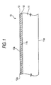
- Fig. 1 is a schematic sectional view of the structure of an optical recording medium according to the preferred embodiment of the invention.
- an optical recording medium 10 comprises a disc body 11, a white ink layer 12 provided on the label side 11b of the disc body 11 and an ink receiving layer 13 provided on the white ink layer 12.
- the white ink layer 12 is a layer formed as the undercoat of the ink receiving layer 13 and the layer provided between the label side 11b of the disc body 11 and the ink receiving layer 13 may be called a "undercoat layer”.
- the disc body 11 has a light incident side 11a onto which a laser beam is emitted at the time of recording and/or playback and a label side 11b as the back of the light incident side 11a.
- Disc bodies 11 are not particularly restricted in kind but can be CD type discs such as CD-ROM, CD-R and CD-RW; DVD type discs such as DVD-ROM, DVD-R and DVD-RW; and further next-generation type optical discs for which a laser beam in the blue wavelength region is used.
- Figs. 2A to 2C show examples of disc bodies 11 to which the invention is properly applicable, including Fig. 2A is a CD type disc, Fig. 2B a DVD type disc and Fig. 2C a next-generation type disc.
- the CD type disc has a light-transmission substrate 21 about 1.2 mm thick with its one side used as the light incident side 11a, a functional layer 22 provided on the other side of the light-transmission substrate 21 and a protective layer 23 covering the functional layer 22, the surface of the protective layer 23 corresponding to the label side 11b. Accordingly, the white ink layer 12 and the ink receiving layer 13 are provided on the surface (label side 11b) of the protective layer 23 when the CD type disc shown in Fig. 2A is used as the disc body 11.
- the structure and material of the functional layer 22 vary with the kind of the disc as follows: in the case of a ROM type disc such as CD-ROM, the functional layer 22 is formed with a reflective layer containing metal; in the case of a WO type disc such as CD-R, the functional layer 22 is formed with a recording layer containing organic coloring matter as well as a reflective layer containing metal, formed on the recording layer; and in the case of a rewritable disc such as CD-RW is formed with a recording layer containing phase-change material, a plurality of dielectric layers with the recording layer held therebetween and a reflective layer containing metal.
- the DVD type disc has a light-transmission substrate 31 about 0.6 mm thick with its one side used as the light incident side 11a, a dummy substrate 32 with its one side used as the label side 11b, a functional layer 33 provided on the other side of the light-transmission substrate 31, a protective layer 34 covering the functional layer 33, and an adhesive layer 35 for bonding the laminate composed of the light-transmission substrate 31, the functional layer 33 and the protective layer 34 to the adhesive layer 35.
- the white ink layer 12 and the ink receiving layer 13 are provided on the surface (label side 11b) of the dummy substrate 32 when the DVD type disc shown in Fig. 2 (b) is used as the disc body 11.
- the structure and material of the functional layer 33 vary with the kind of the disc as follows: in the case of a ROM type disc such as DVD-ROM like the CD type disc, the functional layer 33 is formed with a reflective layer containing metal; in the case of a WO type disc such as DVD-R, the functional layer 33 is formed with a recording layer containing organic coloring matter as well as a reflective layer containing metal, formed on the recording layer; and in the case of a rewritable disc such as DVD-RW is formed with a recording layer containing phase-change material, a plurality of dielectric layers with the recording layer held therebetween and a reflective layer containing metal.
- the next-generation type disc has a support substrate 41 about 1.1 mm with its one end used as the label side 11b, a functional layer 42 provided on the other side of the support substrate 41 and a light-transmission substrate 43 covering the functional layer 42, the surface of the light-transmission substrate 43 corresponding to the light incident side 11a. Accordingly, the white ink layer 12 and the ink receiving layer 13 are provided on the surface (label side 11b) of the support substrate 41 when the next-generation type disc shown in Fig. 2C is used as the disc body 11.
- the structure and material of the functional layer 42 vary with the kind of the disc; in the case of a rewritable disc proposed now, the functional layer 42 is formed with a recording layer containing phase-change material, a plurality of dielectric layers with the recording layer held therebetween and a reflective layer containing metal.
- discs shown in Figs. 2A to 2C are disc-shaped and about 1.2 mm in thickness and about 120 mm in diameter
- discs to which the invention is applicable are not limited to those shown therein but may be one of any type as long as it has the light incident side 11a and the label side 11b opposite thereto.
- the disc-like external form is not indispensable and not only the light incident side 11a but also the label side 11b may be rectangular.
- the white ink layer 12 and the ink receiving layer 13 will be described next.
- the white ink layer 12 is a white-colored layer (undercoat layer) as the undercoat of the ink receiving layer 13 and provided so as to improve printing quality by mainly improving the color development.
- the mean roughness (Ra) of the surface 12a of the white ink layer 12 is set not greater than 0.2 ⁇ m and preferably not greater than 0.1 ⁇ m.
- the thickness of the white ink layer 12 is not particularly restricted but may preferably be set not less than 8 ⁇ m and not greater than 15 ⁇ m.
- use can typically be made of material containing ultraviolet-curable resin and especially ultraviolet-curable acrylic resin containing not less than 10wt% and not greater than 30wt% of titanium oxide as well as having a lower shrinkage factor.
- the white ink layer 12 it is preferable to form the white ink layer 12 by the screen printing method. More specifically, it is preferable to cure the white ink layer 12 by irradiating the layer with ultraviolet rays after the uncured white ink layer 12 containing ultraviolet-curable resin is formed by the screenprintingmethod. This is because the use of the screen printing method for forming the white ink layer 12 makes the film thickness substantially constant in the inner and outer peripheral portions as the film thickness distribution becomes reduced. In case that the film distribution of the white ink layer 12 is large, there is the possibility that a difference in color development is caused between the thin and thick areas of the white ink layer 12.
- the white ink layer 12 When the white ink layer 12 is formed by the screen printing method, many irregularities corresponding to the screen mesh are formed on the surface 12a with the white ink layer 12 uncured immediately after the screen printing and the mean roughness (Ra) exceeds 0.2 ⁇ m and typically remains at about 0.3 ⁇ m.
- the leveling of the surface 12a is needed by placing time to some extent until the white ink layer 12 is cured by irradiating the layer with ultraviolet rays. The time required for leveling the surface 12a varies with the composition of the resin used to form the white ink layer 12, the kind and quantity of a leveling agent to be added, whereupon a proper time corresponding to the requirement has to be set.
- the mean roughness (Ra) of the surface 12a is made reducible simply by using the spin coating method for forming the white ink layer 12, the use of the spin coating method may make a difference in film thickness between the inner and outer peripheral portions (e.g., resulting in a thin inner peripheral portion and a thick outer peripheral portion) and this is unpreferable because a difference in color development arises when printing is done with a printer.
- the ink receiving layer 13 is a layer formed as the outermost layer on one side of the optical recording medium 10 and performs the role of fixing ink on receiving the ink supplied from an ink-jet printer. Printing quality, especially color development and gloss are improved when printing is done with the printer by minimizing the mean roughness (Ra) of the surface 13a of the ink receiving layer 13.
- the mean roughness (Ra) of the surface 13a of the ink receiving layer 13 is required to be not greater than 0.2 ⁇ m and preferably not greater than 0.1 ⁇ m.
- the thickness of the ink receiving layer 13 is not particularly restricted but may preferably be set not less than 10 ⁇ m and not greater than 30 ⁇ m.
- the ink receiving layer 13 is preferably made of material with hydrophilic resin such as polyvinyl alcohol and polyvinyl acetal as the main ingredients mixed with cationic polymer as an ink fixing agent.
- the spin coating method or the slit coating method is used to form the ink receiving layer 13.
- the spin coating method includes the steps of dropping an application liquid (a liquid prepared by diluting the material of the ink receiving layer 13 dissolved in a solvent with water or any other solvent) onto the center or the vicinity of the center of the surface (12a) of an object to be processed and turning the processing object whereby to spread the application liquid in the outer peripheral direction by centrifugal force.
- the slit coating method includes the steps of supplying an application liquid from a slit provided in a head and spreading the application liquid over the surface of an object to be processed by moving the relative position between the head and the processing object.
- the slit coating method is a coating method normally used for the processing object (e.g., a display panel) having a rectangular surface and in case where this method is used for disc-shaped objects to be processed such as optical discs in general, a great deal of difficulty is accompanied thereby. Consequently, itisnecessary to devise a way to deal with the case where the disc body 11 is disc-shaped.
- the reason for the use of the spin coating method or the slit coating method for forming the ink receiving layer 13 is that the mean roughness (Ra) of the surface 13a can be made reducible by using one of these coating methods.
- Ra mean roughness
- the distribution of the film thickness of the ink receiving layer 13 tends to grow larger with the spin coating method or the slit coating method used in comparison with the use of the screen printing method, the printing quality is hardly affected by a modicum of the film thickness distribution since the ink receiving layer 13 is fundamentally transparent.
- the ink receiving layer 13 is formed by the spin coating method or the slit coating method, the surface property of the white ink layer 12 as the undercoat is greatly reflected on the formation of the ink receiving layer 13 unlike the case of using the screen printing method.
- the mean roughness (Ra) of the surface 12a of the white ink layer 12 directly appears as the mean roughness (Ra) of the surface 13a of the ink receiving layer 13. Consequently, the mean roughness (Ra) of the surface 12a of the white ink layer 12 is set not greater than 0.2 ⁇ m according to the invention, whereby the mean roughness (Ra) of the surface 13a of the ink receiving layer 13 can also be set not greater than 0.2 ⁇ m.
- the mean roughness (Ra) of the surface 12a of the white ink layer 12 is not greater than 0.2 ⁇ m in the optical recording medium 10 thus configured, the mean roughness (Ra) of the surface 13a of the ink receiving layer 13 is sufficiently reducible. Accordingly, color development and gloss close to those of the film photo are obtainable when printing is done with the ink-jet printer.
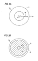
- Figs. 3A and 3B are schematic depiction illustrating the way to form the ink receiving layer 13 on the disc-shaped body 11 by the slit coating method: Fig. 3A indicates the positional relation between the disc body 11 and the slit; and Fig. 3B, a coating area by means of slit coating.
- the longer direction of a slit 50 is matched to the radial direction of the disc body 11 so that one end 51 of the slit 50 provided on a head (not shown) for use in supplying an application liquid matches with the innermost peripheral portion of a coating area and that the other end 52 of the slit 50 matches with the outermost peripheral portion of the coating area when a slit coat is applied to the disc-shaped body 11.
- the disc body 11 is turned or the head is turned along the disc body 11 in this condition whereby to move the relative positional relation therebetween.
- the application liquid is spread in the form of a doughnut on the coating surface (surface 12a of the white ink layer 12) and then the ink receiving layer 13 is formed by letting the solvent evaporate.
- a liquid-application starting area substantially matches with a liquid-application ending area unlike the case of coating an object to be processed such as a display panel having a rectangular surface. Therefore, as shown in Fig. 3B, the film thickness of an area 60 forming a joint becomes slightly greater than the thickness of any other portion. In other words, there is produced a slight difference in level in the area 60 where the joint is formed.
- Fig. 4 is a sectional view taken on line A - A of Fig. 3B, showing the condition above. As shown in Fig.
- the film thickness T1 of the area 60 as the joint and the mean film thickness T2 on the periphery of the area 60 have a relationship of T1 > T2, so that a step, that is difference in level therebetween, as defined by T1 - T2 arises.
- the disc body 11 When the coating film is dried immediately after slit coating is completed, such a step (difference in level) normally exceeds 1.0 ⁇ m and in order to make the step have a gentle slope up to a level not greater than 1.0 ⁇ m, the disc body 11 has to be turned for a certain interval of time until the coating film is heat-dried after slit coating is carried out so as to subject the surface 13a to leveling by centrifugal force.
- the time required for leveling varies with the composition of the material used for the disc body 11, the kind and quantity of the solvent used to dissolve the material and further the number of revolutions of the disc body 11, the time required therefor has to be properly set.
- the number of revolutions of the disc body 11 at the leveling time has to be set smaller to the extent that the film thickness of the ink receiving layer 13 is not excessively decreased; for example, not less than 50 rpm and not greater than 300 rpm.
- the obj ect has a distinctive character in that the linear velocity of the head differs between the inner and outer peripheral portions of the coating surface.
- the application liquid supplied by the slit 50 is uniform from one end 51 corresponding to the innermost periphery over the other end 52 corresponding to the outermost periphery, it is likely that the ink receiving layer 13 formed becomes thick in the inner peripheral portion and becomes thin in the outer peripheral portion.
- the distribution of the film thickness of the ink receiving layer 13 is restrained by increasing the amount of application liquid supplied from one end 51 corresponding to the innermost periphery to the other end 52 corresponding to the outermost periphery; in order to realize this, the profile of the slit 50 is fan-shaped as shown in Fig. 5 by setting the slit width W2 at the other end 52 corresponding to the outermost peripheral portion greater than the slit width W1 at one end 51 corresponding to the innermost peripheral portion of an area to be coated therewith.
- the mean roughness (Ra) of the surface 12a of the white ink layer 12 directly appears as the mean roughness (Ra) of the surface 13a of the ink receiving layer 13. Consequently, the mean roughness (Ra) of the surface 12a of the white ink layer 12 is preferably set not greater than 0.2 ⁇ m, whereby the mean roughness (Ra) of the surface 13a of the ink receiving layer 13 can also be set not greater than 0.2 ⁇ m.
- optical recording medium 10 is thus formedby the producingmethod as described above.
- the step in the area 60 as the joint of the ink receiving layer 13 is restrained to not greater than 1.0 ⁇ m, so that the joint becomes substantially inconspicuous when printing is done with the printer.
- the mean roughness (Ra) of the surface 13a of the ink receiving layer 13 is made sufficiently reducible by setting the mean roughness (Ra) of the surface 12a of the white ink layer 12 not greater than 0.2 ⁇ m, whereby color development and gloss close to those of the film photo are obtainable when printing is done with the ink-jet printer.
- the mean roughness (Ra) of the surface 12a of the white ink layer 12 as the undercoat of the ink receiving layer 13 is set not greater than 0.2 ⁇ m and preferably not greater than 0.1 ⁇ m to ensure that the mean roughness (Ra) of the surface 13a of the ink receiving layer 13 formed by the spin coating method or the slit coating method is made reducible thereby. Consequently, color development and gloss close to those of the film photo are obtainable when printing is done with the ink-jet printer.
- the step at the joint area 60 of the ink receiving layer 13 formed by the slit coating method according to the embodiment of the invention is restrained to not greater than 1.0 ⁇ m and preferably not greater than 0. 5 ⁇ m, the join becomes inconspicuous even when printing is done with the ink-jet printer, so that high printing quality is available.
- the white ink layer 12 is formed directly on the label side 11b of the disc body 11 in the optical recording medium 10 according to the above embodiment of the invention, another layer may be placed between the disc body 11 and the white ink layer 12.
- another layer can be placed between the white ink layer 12 and the ink receiving layer 13, further, the mean roughness (Ra) of the layer placed beneath the ink receiving layer 13 has to be not greater than 0.2 ⁇ m in this case.
- the mean roughness (Ra) of the surface of the undercoat layer existing between the label side 11b of the disc body 11 and the ink receiving layer 13 is only needed to be set not greater than 0.2 ⁇ m.
- the white ink layer 12 is formed directly on the label side 11b of the disc body 11 in the optical recording medium 10 according to the above embodiment of the invention, another layer may be placed between the disc body 11 and the white ink layer 12.
- the mean roughness (Ra) of the surface of the layer placed beneath the ink receiving layer 13 is preferably not greater than 0.2 ⁇ m in this case.
- the mean roughness (Ra) of the surface of the undercoat layer existing between the label side 11b of the disc body 11 and the ink receiving layer 13 is preferably not greater than 0.2 ⁇ m.
- the coating film may undergo natural leveling not by turning the disc body 11 but by simply leaving the coating film as it is.
- a sample of an optical recording medium having the same structure as that of the optical recording medium 10 shown in Fig. 1 was produced by the following method. With respect the disc body 11, a disc of the DVD structure shown in Fig. 2B was used.
- an ultraviolet-curable resin about 10 ⁇ m thick was formed on the surface (label side 11b) of a dummy substrate 32 by screen printing using a screen mesh of No. #420.
- the material of the ultraviolet-curable resin Seika-Beam SCR-VID F29 white of Dainichiseika Color & Chemicals Mfg. Co., Ltd was used.
- the ultraviolet-curable resin thus formed was irradiated with ultraviolet rays to form a white ink layer 12 by curing the resin.
- a duration of five minutes was set from the screen printing up to ultraviolet radiation.
- the surface roughness of the surface 12a of the white ink layer 12 was measured by using Surfcorder SE-3400 of Kosaka Laboratory Ltd. As a result, the mean roughness (Ra) of the surface 12a of the white ink layer 12 was 0.026 ⁇ m and the maximum roughness (Ry) thereof was 0.18 ⁇ m.
- An application liquid containing 10 - 15wt% of PVA (polyvinyl alcohol), 75 - 85wt% of water, 5 - 10wt% of IPA (isopropyl alcohol) and not greater than 5wt% of other material was dropped by the spin coating method and applied to the surface 12a of the white ink layer 12 by turning the disc body 11. Then the coating film was dried at 80°C for five minutes to form an ink receiving layer 13 about 10 ⁇ m thick thereby. The shake-off number of revolutions in spin coating was set to 400 rpm. Then the Surfcorder SE-3400 mentioned above was used to measure the surface roughness of the surface 13a of the ink receiving layer 13. As a result, the mean roughness (Ra) of the surface 13a of the ink receiving layer 13 was 0.026 ⁇ m and the maximum roughness (Ry) thereof was 0.18 ⁇ m.
- PVA polyvinyl alcohol
- IPA isopropyl alcohol
- An example 2 of the invention was produced as in example 1 thereof except that when the white ink layer 12 was formed, a duration of three minutes was set from the screen printing up to ultraviolet radiation.
- the mean roughness (Ra) of the surface 12a of the white ink layer 12 was 0.032 ⁇ m and the maximum roughness (Ry) thereof was 0.21 ⁇ m.
- the mean roughness (Ra) of the surface 13a of the ink receiving layer 13 was 0.030 ⁇ m and the maximum roughness (Ry) thereof was 0.20 ⁇ m.
- An example 3 of the invention was produced as in example 1 thereof except that when the white ink layer 12 was formed, a duration of one minute and 30 seconds was set from the screen printing up to ultraviolet radiation.
- the mean roughness (Ra) of the surface 12a of the white ink layer 12 was 0.09 ⁇ m and the maximum roughness (Ry) thereof was 0.38 ⁇ m.
- the mean roughness (Ra) of the surface 13a of the ink receiving layer 13 was 0.08 ⁇ m and the maximum roughness (Ry) thereof was 0.28 ⁇ m.
- An example 4 of the invention was produced as in example 1 thereof except that when the white ink layer 12 was formed, a duration of one minute was set from the screen printing up to ultraviolet radiation.
- the mean roughness (Ra) of the surface 12a of the white ink layer 12 was 0.11 ⁇ m and the maximum roughness (Ry) thereof was 0.62 ⁇ m.
- the mean roughness (Ra) of the surface 13a of the ink receiving layer 13 was 0.09 ⁇ m and the maximum roughness (Ry) thereof was 0.41 ⁇ m.
- a comparative example 1 was produced as in example 1 of the invention except that when a white ink layer 12 was formed, a duration of 30 seconds was set from the screen printing up to ultraviolet radiation.
- the mean roughness (Ra) of the surface 12a of the white ink layer 12 was 0.21 ⁇ m and the maximum roughness (Ry) thereof was 0.94 ⁇ m.
- the mean roughness (Ra) of the surface 13a of the ink receiving layer 13 was 0.14 ⁇ m and the maximum roughness (Ry) thereof was 0.87 ⁇ m.
- a comparative example 2 was produced as in example 1 of the invention except that when the white ink layer 12 was formed, a duration of 2 seconds was set from the screen printing up to ultraviolet radiation.
- the mean roughness (Ra) of the surface 12a of the white ink layer 12 was 0.28 ⁇ m and the maximum roughness (Ry) thereof was 1.24 ⁇ m.
- the mean roughness (Ra) of the surface 13a of the ink receiving layer 13 was 0.19 ⁇ m and the maximum roughness (Ry) thereof was 0.95 ⁇ m.
- An example of an optical recording medium having the same structure as that of the optical recording medium 10 shown in Fig. 1 was produced by the following method. With respect the disc body 11, a disc of the DVD structure shown in Fig. 2B was used.
- an ultraviolet-curable resin about 10 ⁇ m thick was formed on the surface (label side 11b) of a dummy substrate 32 by screen printing using a screen mesh of No. #420.
- the material of the ultraviolet-curable resin Seika-Beam SCR-VID F29 white of Dainichiseika Color & Chemicals Mfg. Co., Ltd was used.
- the ultraviolet-curable resin thus formed was irradiated with ultraviolet rays to form a white ink layer 12 by curing the resin.
- a duration of one minute was set from the screen printing up to ultraviolet radiation.
- a head having a fan-shaped slit having a slit width W1 of 0.08 mm at one end 51 corresponding to the innermost peripheral portion and a slit width W2 of 0.12 mm at the other end 52 corresponding to the outermost peripheral portion is used.
- the head is placed closer up to 0.90 mm to the surface 12a of a white ink layer 12 and by turning a disc body 11 at 14 rpm in this condition, an application liquid (having a viscosity of 500 cps) containing 10 - 15wt% of PVA (polyvinyl alcohol), 75 - 85wt% of water, 5 - 10wt% of IPA (isopropyl alcohol) and not greater than 5wt% of other material was applied by slit coating to the surface 12a of the white ink layer 12 within a 20 - 58 mm radius from the center of the disc body 11. Then the coating film was subjected to leveling by turning the disc body 11 at 100 rpm for 15 seconds before being dried at 80°C for five minutes whereby to form an ink receiving layer 13 about 10 ⁇ m thick.
- PVA polyvinyl alcohol
- IPA isopropyl alcohol
- ETA-RT of STEAG ETA-OPTIC GmbH Co. was used to measure the coating film of the ink receiving layer 13 at a 40 mm radial point by an optical interference method.
- the film thickness of an area 60 as a joint portion was 10.2 ⁇ m and the mean roughness (Ra) thereof on the periphery of the area 60 was 9.8 ⁇ m.
- An example 6 of the invention was produced as in example 5 thereof except that when the ink receiving layer 13 was formed, a duration of 10 seconds was set as leveling time by turning.
- the film thickness of the ink receiving layer 13 at the 40 mm radial point was 10.6 ⁇ m in the area 60 as the joint portion and the mean film thickness thereof on the periphery of the area 60 was 10.1 ⁇ m.
- An example 7 of the invention was produced as in example 5 thereof except that when the ink receiving layer 13 was formed, a duration of six seconds was set as leveling time by turning.
- the film thickness of the ink receiving layer 13 at the 40 mm radial point was 10.6 ⁇ m in the area 60 as the joint portion and the mean film thickness thereof on the periphery of the area 60 was 9.8 ⁇ m.
- a comparative example 3 was produced as in example 5 thereof except that when an ink receiving layer 13 was formed, a duration of four seconds was set as leveling time by turning. As a result, the film thickness of the ink receiving layer 13 at the 40 mm radial point was 11.6 ⁇ m in the area 60 as the joint portion and the mean film thickness thereof on the periphery of the area 60 was 10.2 ⁇ m.
- a comparative example 4 was produced as in example 5 thereof except that when the ink receiving layer 13 was formed, a duration of two seconds was set as leveling time by turning. As a result, the film thickness of the ink receiving layer 13 at the 40 mm radial point was 12.4 ⁇ m in the area 60 as the joint portion and the mean film thickness thereof on the periphery of the area 60 was 10.1 ⁇ m.
- Comparative example 2 Comparative example 1
- Example 3 Example 2
- Example 1 Leveling time by turning 2 sec. 4 sec. 6 sec. 10 sec. 15 sec Film thickness ( ⁇ m) of ink receiving layer 13 in area 60 12.4 11.6 10.6 10.6 10.2
- x readily confirmable;
- the joint portions were substantially inconspicuous whereby to secure high printing quality in the samples according to Embodiments 5 - 7 of the invention in which differences in the film thickness (steps) were not greater than 1.0 ⁇ m.
- the joint portions became unconfirmable unless carefully observed, so that printing quality was substantially equal to that of the film photo.
Landscapes
- Engineering & Computer Science (AREA)
- Manufacturing & Machinery (AREA)
- Manufacturing Optical Record Carriers (AREA)
- Optical Record Carriers And Manufacture Thereof (AREA)
- Ink Jet Recording Methods And Recording Media Thereof (AREA)
- Application Of Or Painting With Fluid Materials (AREA)
Applications Claiming Priority (4)
| Application Number | Priority Date | Filing Date | Title |
|---|---|---|---|
| JP2003280418 | 2003-07-25 | ||
| JP2003280417 | 2003-07-25 | ||
| JP2003280417A JP2005044478A (ja) | 2003-07-25 | 2003-07-25 | 光記録媒体及びその製造方法 |
| JP2003280418A JP2005044479A (ja) | 2003-07-25 | 2003-07-25 | 光記録媒体及びその製造方法 |
Publications (2)
| Publication Number | Publication Date |
|---|---|
| EP1501089A2 true EP1501089A2 (de) | 2005-01-26 |
| EP1501089A3 EP1501089A3 (de) | 2006-11-29 |
Family
ID=33492511
Family Applications (1)
| Application Number | Title | Priority Date | Filing Date |
|---|---|---|---|
| EP04017547A Withdrawn EP1501089A3 (de) | 2003-07-25 | 2004-07-23 | Optisches Aufzeichnungsmedium und Verfahren zur Herstellung desselben |
Country Status (3)
| Country | Link |
|---|---|
| US (1) | US6984433B2 (de) |
| EP (1) | EP1501089A3 (de) |
| TW (1) | TWI265513B (de) |
Cited By (1)
| Publication number | Priority date | Publication date | Assignee | Title |
|---|---|---|---|---|
| EP1602506A3 (de) * | 2004-05-31 | 2006-06-07 | TDK Corporation | Harzzusammensetzung sowie Verfahren zur Herstellung einer Tintenempfangsschicht, das die Zusammensetzung verwendet |
Families Citing this family (7)
| Publication number | Priority date | Publication date | Assignee | Title |
|---|---|---|---|---|
| JP2005327331A (ja) * | 2004-05-12 | 2005-11-24 | Tdk Corp | 光記録媒体 |
| US7205038B2 (en) * | 2004-06-02 | 2007-04-17 | Tdk Corporation | Optical recording medium and method for manufacturing the same |
| JP3106408U (ja) * | 2004-07-06 | 2005-01-06 | Tdk株式会社 | 光記録媒体 |
| TW200638411A (en) * | 2005-04-29 | 2006-11-01 | Prodisc Technology Inc | Optical recording medium |
| TW200713260A (en) * | 2005-09-28 | 2007-04-01 | Daxon Technology Inc | Optical disc |
| KR101218529B1 (ko) * | 2006-06-30 | 2013-01-21 | 톰슨 라이센싱 | 매체와 사용하기 위한 무선 주파수 트랜스폰더 |
| TWI476766B (zh) * | 2012-06-01 | 2015-03-11 | Cmc Magnetics Corp | An optical recording medium and a method of forming a printable layer on an optical recording medium |
Family Cites Families (16)
| Publication number | Priority date | Publication date | Assignee | Title |
|---|---|---|---|---|
| US5549952A (en) * | 1992-06-13 | 1996-08-27 | Sony Corporation | Optical information medium and method for printing on the surface of the medium |
| KR0185765B1 (ko) * | 1993-04-10 | 1999-04-15 | 가와다 미쓰구 | 광 정보매체와 그 제조방법 |
| JP3364336B2 (ja) * | 1994-09-08 | 2003-01-08 | ティーディーケイ株式会社 | 光ディスクおよび被記録材 |
| US5972457A (en) * | 1996-12-03 | 1999-10-26 | Mitsubishi Chemical Corporation | Optical recording medium |
| JP3521716B2 (ja) | 1997-11-25 | 2004-04-19 | 凸版印刷株式会社 | 回転塗布装置用塗液供給装置 |
| DE19857315A1 (de) * | 1997-12-12 | 1999-08-05 | Ricoh Kk | Optisches Informationsspeichermaterial und Anzeige-Aufzeichnungsverfahren unter Verwendung desselben |
| JP3586551B2 (ja) * | 1998-01-27 | 2004-11-10 | 松下電器産業株式会社 | 光記録媒体の製造方法及び製造装置 |
| JP2000167476A (ja) | 1998-12-10 | 2000-06-20 | Toppan Printing Co Ltd | 着色被膜の形成方法 |
| ATE354166T1 (de) * | 2000-04-25 | 2007-03-15 | Matsushita Electric Industrial Co Ltd | Verfahren zur herstellung eines plattensubstrats und verfahren und vorrichtung zur herstellung einer optischen platte |
| EP1154418B1 (de) * | 2000-04-27 | 2008-07-16 | Mitsubishi Kagaku Media Co., Ltd. | Optisches Aufzeichnungsmedium |
| JP4110737B2 (ja) | 2001-02-08 | 2008-07-02 | 三菱化学メディア株式会社 | 光記録媒体 |
| JP2002337443A (ja) * | 2001-05-18 | 2002-11-27 | Konica Corp | インクジェット記録方法及び記録物 |
| TWI242206B (en) * | 2001-06-22 | 2005-10-21 | Fuji Photo Film Co Ltd | Optical information recording medium |
| JP2003072247A (ja) * | 2001-08-30 | 2003-03-12 | Konica Corp | 中間転写受像シート及びそれを用いた画像形成方法 |
| JP2003123323A (ja) * | 2001-10-03 | 2003-04-25 | Sony Corp | 光情報媒体 |
| JP2005111836A (ja) * | 2003-10-08 | 2005-04-28 | Fuji Photo Film Co Ltd | 情報媒体 |
-
2004
- 2004-07-23 TW TW093122026A patent/TWI265513B/zh not_active IP Right Cessation
- 2004-07-23 US US10/897,006 patent/US6984433B2/en not_active Expired - Lifetime
- 2004-07-23 EP EP04017547A patent/EP1501089A3/de not_active Withdrawn
Cited By (1)
| Publication number | Priority date | Publication date | Assignee | Title |
|---|---|---|---|---|
| EP1602506A3 (de) * | 2004-05-31 | 2006-06-07 | TDK Corporation | Harzzusammensetzung sowie Verfahren zur Herstellung einer Tintenempfangsschicht, das die Zusammensetzung verwendet |
Also Published As
| Publication number | Publication date |
|---|---|
| EP1501089A3 (de) | 2006-11-29 |
| US20050053749A1 (en) | 2005-03-10 |
| TW200509118A (en) | 2005-03-01 |
| TWI265513B (en) | 2006-11-01 |
| US6984433B2 (en) | 2006-01-10 |
Similar Documents
| Publication | Publication Date | Title |
|---|---|---|
| EP1759868B1 (de) | Optisches Informationsaufzeichnungsmaterial und Verfahren zu dessen Herstellung | |
| US6984433B2 (en) | Optical recording medium and method of producing the same | |
| US7820234B2 (en) | Manufacturing method of optical information recording medium | |
| US6507550B1 (en) | Optical data storage medium | |
| US20050270963A1 (en) | Optical recording medium | |
| KR100493264B1 (ko) | 광정보 기록 매체와 그 제조 방법 및 광정보의 기록 재생방법 | |
| JP5201981B2 (ja) | 情報記録媒体 | |
| JP4286841B2 (ja) | 光情報記録媒体及びその製造方法 | |
| EP1669991B1 (de) | Herstellungsverfahren für ein mehrschichtiges informationsaufzeichnungsmedium | |
| US7205038B2 (en) | Optical recording medium and method for manufacturing the same | |
| JP5108434B2 (ja) | 光記録媒体の製造方法及び製造装置 | |
| JP2009080871A (ja) | 光情報記録媒体 | |
| JP2005044479A (ja) | 光記録媒体及びその製造方法 | |
| US7052759B2 (en) | Optical recording medium | |
| WO2008041526A1 (en) | Method and apparatus for manufacturing optical recording medium | |
| JP2569627Y2 (ja) | 光ディスク用基板 | |
| JP2005044478A (ja) | 光記録媒体及びその製造方法 | |
| JP2007048389A (ja) | 光ディスクおよびその製造方法 | |
| JP2007052892A (ja) | 光情報記録媒体 | |
| US20050238837A1 (en) | Optical recording medium | |
| JP4708316B2 (ja) | 光情報記録媒体 | |
| JP2010108572A (ja) | 光記録媒体の製造方法及び製造装置 | |
| JP2010134978A (ja) | 光記録媒体の製造方法及び製造装置 | |
| US20040175531A1 (en) | Optical disc and method for manufacturing the same | |
| JP2007220225A (ja) | 光情報記録媒体 |
Legal Events
| Date | Code | Title | Description |
|---|---|---|---|
| PUAI | Public reference made under article 153(3) epc to a published international application that has entered the european phase |
Free format text: ORIGINAL CODE: 0009012 |
|
| AK | Designated contracting states |
Kind code of ref document: A2 Designated state(s): AT BE BG CH CY CZ DE DK EE ES FI FR GB GR HU IE IT LI LU MC NL PL PT RO SE SI SK TR |
|
| AX | Request for extension of the european patent |
Extension state: AL HR LT LV MK |
|
| PUAL | Search report despatched |
Free format text: ORIGINAL CODE: 0009013 |
|
| AK | Designated contracting states |
Kind code of ref document: A3 Designated state(s): AT BE BG CH CY CZ DE DK EE ES FI FR GB GR HU IE IT LI LU MC NL PL PT RO SE SI SK TR |
|
| AX | Request for extension of the european patent |
Extension state: AL HR LT LV MK |
|
| STAA | Information on the status of an ep patent application or granted ep patent |
Free format text: STATUS: THE APPLICATION IS DEEMED TO BE WITHDRAWN |
|
| AKX | Designation fees paid | ||
| 18D | Application deemed to be withdrawn |
Effective date: 20070201 |
|
| REG | Reference to a national code |
Ref country code: DE Ref legal event code: 8566 |