EP1500928A1 - Méthode par courants de Foucault pour test de qualité - Google Patents
Méthode par courants de Foucault pour test de qualité Download PDFInfo
- Publication number
- EP1500928A1 EP1500928A1 EP04405450A EP04405450A EP1500928A1 EP 1500928 A1 EP1500928 A1 EP 1500928A1 EP 04405450 A EP04405450 A EP 04405450A EP 04405450 A EP04405450 A EP 04405450A EP 1500928 A1 EP1500928 A1 EP 1500928A1
- Authority
- EP
- European Patent Office
- Prior art keywords
- eddy current
- moldings
- current measuring
- measurement
- capsules
- Prior art date
- Legal status (The legal status is an assumption and is not a legal conclusion. Google has not performed a legal analysis and makes no representation as to the accuracy of the status listed.)
- Withdrawn
Links
- 238000000034 method Methods 0.000 title claims abstract description 33
- 238000012372 quality testing Methods 0.000 title 1
- 238000005259 measurement Methods 0.000 claims abstract description 42
- 239000002775 capsule Substances 0.000 claims description 71
- 238000000465 moulding Methods 0.000 claims description 46
- 230000002950 deficient Effects 0.000 claims description 8
- 230000008569 process Effects 0.000 claims description 8
- 229910052782 aluminium Inorganic materials 0.000 claims description 6
- XAGFODPZIPBFFR-UHFFFAOYSA-N aluminium Chemical compound [Al] XAGFODPZIPBFFR-UHFFFAOYSA-N 0.000 claims description 6
- 239000004020 conductor Substances 0.000 claims description 3
- 239000002689 soil Substances 0.000 claims description 2
- 238000004519 manufacturing process Methods 0.000 description 8
- 235000013305 food Nutrition 0.000 description 5
- 230000007246 mechanism Effects 0.000 description 5
- 230000007547 defect Effects 0.000 description 3
- 239000000463 material Substances 0.000 description 3
- 238000004080 punching Methods 0.000 description 3
- 238000003908 quality control method Methods 0.000 description 3
- 238000012360 testing method Methods 0.000 description 3
- 239000012611 container material Substances 0.000 description 2
- 238000011143 downstream manufacturing Methods 0.000 description 2
- 239000000843 powder Substances 0.000 description 2
- 238000012546 transfer Methods 0.000 description 2
- 238000012935 Averaging Methods 0.000 description 1
- 238000009825 accumulation Methods 0.000 description 1
- 230000004913 activation Effects 0.000 description 1
- 239000011324 bead Substances 0.000 description 1
- 230000008901 benefit Effects 0.000 description 1
- 238000000071 blow moulding Methods 0.000 description 1
- 230000007812 deficiency Effects 0.000 description 1
- 230000001419 dependent effect Effects 0.000 description 1
- 238000000151 deposition Methods 0.000 description 1
- 239000000645 desinfectant Substances 0.000 description 1
- 239000003651 drinking water Substances 0.000 description 1
- 235000020188 drinking water Nutrition 0.000 description 1
- 239000012530 fluid Substances 0.000 description 1
- 238000007689 inspection Methods 0.000 description 1
- 239000007788 liquid Substances 0.000 description 1
- 229910052751 metal Inorganic materials 0.000 description 1
- 239000002184 metal Substances 0.000 description 1
- 230000003287 optical effect Effects 0.000 description 1
- 238000000275 quality assurance Methods 0.000 description 1
- 239000000523 sample Substances 0.000 description 1
- 238000007789 sealing Methods 0.000 description 1
- 239000007858 starting material Substances 0.000 description 1
- 239000000126 substance Substances 0.000 description 1
- 239000002699 waste material Substances 0.000 description 1
Images


Classifications
-
- G—PHYSICS
- G01—MEASURING; TESTING
- G01N—INVESTIGATING OR ANALYSING MATERIALS BY DETERMINING THEIR CHEMICAL OR PHYSICAL PROPERTIES
- G01N27/00—Investigating or analysing materials by the use of electric, electrochemical, or magnetic means
- G01N27/72—Investigating or analysing materials by the use of electric, electrochemical, or magnetic means by investigating magnetic variables
- G01N27/82—Investigating or analysing materials by the use of electric, electrochemical, or magnetic means by investigating magnetic variables for investigating the presence of flaws
- G01N27/90—Investigating or analysing materials by the use of electric, electrochemical, or magnetic means by investigating magnetic variables for investigating the presence of flaws using eddy currents
- G01N27/9093—Arrangements for supporting the sensor; Combinations of eddy-current sensors and auxiliary arrangements for marking or for rejecting
-
- B—PERFORMING OPERATIONS; TRANSPORTING
- B07—SEPARATING SOLIDS FROM SOLIDS; SORTING
- B07C—POSTAL SORTING; SORTING INDIVIDUAL ARTICLES, OR BULK MATERIAL FIT TO BE SORTED PIECE-MEAL, e.g. BY PICKING
- B07C5/00—Sorting according to a characteristic or feature of the articles or material being sorted, e.g. by control effected by devices which detect or measure such characteristic or feature; Sorting by manually actuated devices, e.g. switches
- B07C5/34—Sorting according to other particular properties
- B07C5/3404—Sorting according to other particular properties according to properties of containers or receptacles, e.g. rigidity, leaks, fill-level
-
- B—PERFORMING OPERATIONS; TRANSPORTING
- B07—SEPARATING SOLIDS FROM SOLIDS; SORTING
- B07C—POSTAL SORTING; SORTING INDIVIDUAL ARTICLES, OR BULK MATERIAL FIT TO BE SORTED PIECE-MEAL, e.g. BY PICKING
- B07C5/00—Sorting according to a characteristic or feature of the articles or material being sorted, e.g. by control effected by devices which detect or measure such characteristic or feature; Sorting by manually actuated devices, e.g. switches
- B07C5/34—Sorting according to other particular properties
- B07C5/344—Sorting according to other particular properties according to electric or electromagnetic properties
Definitions
- the present invention relates to a method for rejecting defective ones Moldings made of electrically conductive material.
- the present invention relates Invention an apparatus for performing such a method.
- containers are often made of aluminum in one Forming process produced.
- Such containers can also be provided with deposits which can fulfill the most diverse functions.
- containers containing moisture-sensitive powder may be filled with one Be provided, which absorbs the moisture and keeps the powder dry.
- Other containers containing liquids may be self-sealing Inserts should be provided so that leakage occurs despite damage to the container content is prevented.
- Other applications are to provide deposits, which release a substance into the main space upon activation, e.g. at Capsules or cups for drinking water could be the case, in which after a Piercing or similar dispensed a disinfectant fluid in a controlled dosage becomes.
- the containers are made of a container material web, for example a Aluminum band, shaped. They are punched out of a train and then by forming, such as deep drawing or blow molding, manufactured. The any existing deposits are made of a band-shaped Punched material web before they are inserted into the container.
- defects can consist of a defective structure, which may be, on the one hand, actual cracks in the metal layer, or else weak spots, which can break at the lowest load.
- Such cracks or weak points are usually undesirable in the field of containers of the food industry, since they can endanger the airtightness, and thus the durability of the products held in the containers is not guaranteed.
- such container can often a filling downstream process in z. B. can not withstand a back pressure autoclave, or it may cause such defects, for example, when used as coffee capsules to break up the capsules in the corresponding machine at the consumer.
- the invention is therefore based on the object, a structurally simple, fast, reliable method for rejecting defective moldings electrically conductive material, d. H.
- electrically conductive material d. H.
- food containers Aluminum for example, food containers Aluminum, to provide.
- the blanks are automatically fed, cup-shaped body with a bottom, and these moldings become one Non-contact eddy current measurement at at least two measurement frequencies subjected to the eddy current measurement of the cup-shaped body of his Bottom-facing side comprises at least one eddy current measuring head becomes.
- the molding it is possible, the molding to some extent not from the outside, but from the inside by measuring the eddy current through the bottom invaded opening penetrates into the cup-shaped body. Such a measurement is Of course, only possible if the container is not filled respectively not yet provided with a lid. With over resp. Fall below one Tolerance deviation of reference values becomes the measured shape discarded.
- the essence of the invention is therefore to recognize that, surprisingly Also cup-shaped body at high speed using a Eddy current measurement can be measured, and based on such Eddy current measurement defective moldings are automatically sorted out can. It turns out that already at measuring times of a few hundred ms and at Few data frequencies are enough data to structure errors or Reliably detect chips and the corresponding moldings from the process too remove. So can a high quality assurance at high cadence be guaranteed.
- a first preferred embodiment of the method according to the invention is characterized characterized in that the same non-contact eddy current measurement on a error-free reference molding, and that on the reference molding measured values are used as reference values.
- the determination of (Absolutely not interesting anyway) absolute values as reference values can so in elegant way can be bypassed, for example, can temperature-related or similar drifts are compensated.
- the measurement on one Such Referenzformling can either before running a series happen, or more preferably during the entire time in which Moldings are to be singled out.
- the process can be further improved by the reference values or tolerance deviations over a teaching procedure z.
- B. in terms of temperature-induced drifts or in terms of a Structure compensation can be adjusted continuously or in sections.
- Another preferred embodiment is characterized in that it is at the moldings are moldings from a forming process.
- the formed material is optionally coated aluminum act. It is preferably conical to the bottom, cup-shaped Moldings, such as those associated with the production of Coffee capsules for automated use in coffee machines application Find.
- the moldings on a cycle in particular with after top ground, fed, and it is the eddy current in a Standstill phase of the cycle initially in such a way from the side of the floor over the particular molding out that this at least partially in a cavity of the Eddy current measuring head is recorded. Subsequently, the actual Eddy current measurement made, and finally the eddy current measuring device is again removed from the molding, before the clock belt transported on. It is also possible the ground-down with ground-by-side juxtaposed moldings before the eddy current measurement in particular preferred to turn in pairs and then with upwardly directed soil, if necessary, at the same time Spread, the eddy current measuring head respectively the multiplicity of parallel Supply eddy current measuring heads.
- a further preferred embodiment is characterized in that the Moldings, in particular, preferably in strips next to each other on tapes intermittently be fed, and after the eddy current measurement via a stacking slide after their supply via a conveyor belt only the defect-free moldings particularly preferred to be stacked upwards, while defective moldings be discarded over the running of the conveyor belt.
- the rejection can be realized so efficiently and easily. The discarded moldings fall then in a corresponding waste container.
- the eddy current measurement makes sense in succession at least 3, preferably at least 5 discrete different frequencies in the Range from 25 Hz to 25 kHz, preferably in the range of 250 Hz or 600 Hz to 25 kHz, in particular a measuring time in the range of 100 - 200 ms applies.
- the present invention relates to an apparatus for performing a Procedure as described above.
- the device is preferred characterized by at least two eddy current measuring heads with one cavity, which at least partially encloses the molding during the measurement, and which Vortex flow measuring heads preferably at least one encompassing the molding circumferentially Have measuring coil, wherein at least one of the eddy current measuring heads for the Eddy current measurement on a faultless reference blank to determine the Reference values is provided, and at least a second of the eddy current measuring heads is provided for the moldings to be checked.
- a preferred embodiment of the device is characterized in that Ribbons are present on which the moldings in batches, side by side, intermittently be fed, and that one of the number of tracks corresponding number of Eddy current measuring heads is arranged, which on different tracks measures supplied moldings.
- Fig. 1 shows a side view of a device 1 for quality inspection of Coffee capsules.
- a device 1 may, but need not, directly afterwards be arranged on the actual production of capsules.
- the supplied capsules 2 from the left of the device 1 fed are aligned with their opening facing up, and feature optionally already on its inside via a filter arranged on the bottom (circular insert, e.g., non-woven).
- the capsules 2 are cup-shaped, wherein on the side facing the opening a bead is present and wherein the side walls taper at a steep angle to the ground, and the Ground is formed laterally tapering with a shallower angle and angle below has a horizontal circular section.
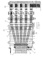
- FIG. 2 which is a view from above of the device.
- Fig. 1 shows As can be seen, the capsules 2 are replaced by a feeder 6, e.g. from Filter applicator supplied in several tracks next to each other. There are 10 tracks driven in parallel and synchronously.
- a feeder 6 e.g. from Filter applicator supplied in several tracks next to each other.
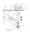
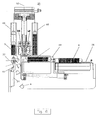
- the suction wheel 14 and the entire Saugrad unit 7 is shown in Fig. 3 in detail shown.
- the unit has a mechanism for generating one
- the up-down movement is effected via a lever by a motor 30, which a Crankshaft 10 for the suction wheel 14 drives, via a connecting rod 11 at one Lever 29 is struck.
- the lever arm 29 is about the axis of the shaft 12 for the Suction wheel 14 rotatably mounted, and the rotation of the crankshaft 10 causes accordingly an up-down movement of the suction wheel 14th
- the rotatability of the suction wheel 14 is ensured by a further motor 31, which drives a shaft 12.
- This shaft 12 is connected via a belt 13 with a corresponding, arranged on the suction wheel 14 roller connected, and it can over this Motor 31, the suction wheel to be rotated about its axis of rotation.
- the suction wheel 14 picks up the capsules 2 arriving from above.
- the suction wheel 14 is slightly up or moved down so that the capsules 2 are released from the feeder 6. Subsequently, the suction wheel 14 is turned by 180 °, so that the two at the suction wheel 14 fixed capsules 2 then with their opening down over the Transport clock belt 8 are arranged. They will then go through a downward movement between existing on the conveyor belt 8 transverse bands 28 in the between deposed existing depressions, so that the capsules on the conveyor belt 8th without being displaced in the conveying direction to be deflected in the lateral direction can (see below).
- the suction wheel 14 by movement of the lever 29 back to moved above and so on the band 8 capsules 3 at least as far Released that the conveyor belt 8 in a next step, the capsules can carry.
- the suction wheel 14 sets accordingly two each on a train located capsules 2 on the conveyor belt 8 from. Because ten such tracks are arranged side by side, are accordingly as already mentioned pro Operating cycle of the suction wheel 20 capsules folded.
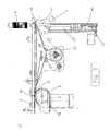
- the eddy current unit 16 is shown in Fig. 4 in detail.
- the measurement is not in the double clock, in which the capsules 3 of the Suction wheel unit 7 are placed on the conveyor belt 8, perform, but in a single cycle, d. H. with double frequency only one capsule 3 at a time measure.
- the eddy current unit 16 is moved in time via the supplied capsules 3.
- the Unit 16 accordingly has at least one eddy current measuring head 17, which has a cavity 35, which substantially the lower outer mold of the Corresponds to capsules.
- a test coil is arranged, which circular surrounds the capsule. It is also possible to have several test coils in one Provide measuring head.
- the individual measuring heads 17 are of a cross rail 36 (see. Also FIG. 2), so that all the measuring heads 17 for the side by side guided Lanes of capsules 3 at the same time and using only one Movement mechanism are slid over the capsules for each measurement can.
- FIG. 4 This movement mechanism is shown in FIG. 4.
- a motor 34 arranged which drives a shaft 18 for the eddy current unit 16.
- This wave is over a belt 19 connected to a crankshaft 20.
- a connecting rod 21 At this crankshaft 20 is eccentrically fastened a connecting rod 21, which then the rail 36th carrying unit is able to move up and down (see arrow).
- the band 8 in each case 2 to be measured Capsules 3 under the unit 16 this is then in the standstill phase of the Bandes 8 lowered onto the capsules 3 by means of the mechanism described above and made the eddy current measurement. After the measurement, which is typically approx.
- the measuring head is raised and the band 8 continued.
- 5 frequencies for example, 600 heart, 1.6 kHz, 4 kHz, 10 kHz, 25 kHz
- the equipment it is for example, a device of the type eddyliner®P from IBG, Ebermannstadt, DE, to use.
- the actual threshold values are, in particular, the Reference values of good capsules are actually not of interest, and also these values vary. From production series to production series due to different starting materials, production conditions etc .. Furthermore the reference values may be subject to drifts or other fluctuations.
- the measurement made on the capsules 3 not compared with absolute values, but it is also at least one (in the Figures not shown) reference device present, in which a reference capsule measured without defect (no structure defect, no spickel). It can now in this reference device either before the start of a series a plurality of Calibration parts (coffee capsules) are measured, and the corresponding Reference values are set. Together with given tolerance deviations Afterwards parts can be sorted out which are not in a window Reference value +/- tolerance value.
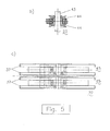
- FIG. 5 Behind the eddy current unit 16 are the measured capsules 3 of Transport clock belt 8 via a dead plate 51 to a continuously running Transfer conveyor 22. This is shown in detail in Fig. 5. It is about in each case by a pair of bands 37, which the capsule 3 only in the Support edge area from below. Between the two bands 37 remains according to a gap 45.
- the two bands 37 are of a Drive roller 23, which is shown in a section in Fig. 5b), driven, wherein in each case the bands 37 are guided in grooves 44.
- the bands 37 are over Guide rollers 38 held in a tensioned state.
- the gap 45 is occupied by the upper part 41 of the stacking pusher 24.
- the Aufstapelschieber 24 in turn comprises a motor 39 with a crankshaft 39, which moves a connecting rod 40 and one on from the movement of Aufstapelschiebers 24 causes. Now reaches a faultless capsule 3 at the end (in Fig. 5a) right) of the Conveyor belt 22 which arranged at the upper part 41 of the stacking slide 24 Nose 42, the further movement of the capsule 3 is prevented. At this moment will be the stacking slide 24 moves upward and the faultless capsule 3 from below in the stack 5 is inserted.
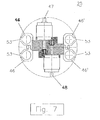
- a stacker 25 is arranged with a turning device. This one is in Detail shown in Fig. 6 and in Fig. 7.
- the stack 5 to the respective web of Capsules 3 is initially guided in a tube 46. Is this tube 46 in sufficient Mass filled with capsules, the unit 25 is rotated about the axis 52 by 180 °.
- two stacks 5 from the conveyor belt 22nd turned away, and then the two are in the unit 25 opposite arranged tubes 46 facing the conveyor belt 22 and can be filled. While now these second tubes are filled, which the conveyor belt 22nd facing away from tubes 46 ', as shown in Fig.
- the band 26 can initially only 2 positions be moved, and only if all arranged behind the stackers 25 Positions are filled, the tape are moved forward by a full width.
- Typical times for the described method can be set as follows. In the described method, only one capsule is passed through the measuring device at a time measured, and not two, as described above.
- the feeder 6 lowers to the suction wheel 14 in about 250 ms. Then there is a stop time of about 360 ms, the suction wheel 14 is then within about 160 ms rotated, where it is also lowered in the last 125 ms. Within about 10 ms the capsules are released and deposited by the suction wheel 14, then the Suction wheel 14 in turn raised within 125 ms.
- the transport clock band 8 is moved by one position (a Capsule) moved forward.
- the eddy current unit 16 is within about 150 ms lowered to the capsule 3, then the eddy current measurement during approx. 150 ms, and then the measuring head raised within about 150 ms.
- the transfer clock belt 8 is moved by one position (a Capsule) moved forward.
- the eddy current unit 16 will turn within about 150 ms lowered to the next capsule 3, then the Eddy current measurement carried out for about 150 ms, and then the measuring head raised within about 150 ms.
Landscapes
- Chemical & Material Sciences (AREA)
- Chemical Kinetics & Catalysis (AREA)
- Electrochemistry (AREA)
- Physics & Mathematics (AREA)
- Health & Medical Sciences (AREA)
- Life Sciences & Earth Sciences (AREA)
- Analytical Chemistry (AREA)
- Biochemistry (AREA)
- General Health & Medical Sciences (AREA)
- General Physics & Mathematics (AREA)
- Immunology (AREA)
- Pathology (AREA)
- Sorting Of Articles (AREA)
- Investigating Or Analyzing Materials By The Use Of Magnetic Means (AREA)
Applications Claiming Priority (2)
| Application Number | Priority Date | Filing Date | Title |
|---|---|---|---|
| CH01285/03A CH696372A5 (de) | 2003-07-23 | 2003-07-23 | Wirbelstrombasiertes Verfahren zur Qualitätsüberprüfung. |
| CH12852003 | 2003-07-23 |
Publications (1)
| Publication Number | Publication Date |
|---|---|
| EP1500928A1 true EP1500928A1 (fr) | 2005-01-26 |
Family
ID=33480365
Family Applications (1)
| Application Number | Title | Priority Date | Filing Date |
|---|---|---|---|
| EP04405450A Withdrawn EP1500928A1 (fr) | 2003-07-23 | 2004-07-14 | Méthode par courants de Foucault pour test de qualité |
Country Status (2)
| Country | Link |
|---|---|
| EP (1) | EP1500928A1 (fr) |
| CH (1) | CH696372A5 (fr) |
Cited By (2)
| Publication number | Priority date | Publication date | Assignee | Title |
|---|---|---|---|---|
| CN112495846A (zh) * | 2020-12-07 | 2021-03-16 | 浙江腾龙精线有限公司 | 一种涡流探伤检测装置 |
| WO2021092345A1 (fr) * | 2019-11-08 | 2021-05-14 | Ball Corporation | Inspection de récipients métalliques par courants de foucault |
Citations (3)
| Publication number | Priority date | Publication date | Assignee | Title |
|---|---|---|---|---|
| US3539006A (en) * | 1968-05-22 | 1970-11-10 | Lamson & Sessions Co | Method and apparatus for inspecting annular articles |
| US4002966A (en) * | 1975-02-21 | 1977-01-11 | National Can Corporation | Apparatus for detecting imperfections on the wall of cylindrical containers |
| US20020015768A1 (en) * | 1999-03-18 | 2002-02-07 | Petr Masek | Sealed cartridge for making a beverage |
-
2003
- 2003-07-23 CH CH01285/03A patent/CH696372A5/de not_active IP Right Cessation
-
2004
- 2004-07-14 EP EP04405450A patent/EP1500928A1/fr not_active Withdrawn
Patent Citations (3)
| Publication number | Priority date | Publication date | Assignee | Title |
|---|---|---|---|---|
| US3539006A (en) * | 1968-05-22 | 1970-11-10 | Lamson & Sessions Co | Method and apparatus for inspecting annular articles |
| US4002966A (en) * | 1975-02-21 | 1977-01-11 | National Can Corporation | Apparatus for detecting imperfections on the wall of cylindrical containers |
| US20020015768A1 (en) * | 1999-03-18 | 2002-02-07 | Petr Masek | Sealed cartridge for making a beverage |
Non-Patent Citations (1)
| Title |
|---|
| ANONYMOUS: "eddyliner P2/P3/P4/P16", INTERNET ARTICLE, 2002, XP002266838, Retrieved from the Internet <URL:http://www.ibgndt.de/html/eddylinerrpx.html> [retrieved on 20040113] * |
Cited By (2)
| Publication number | Priority date | Publication date | Assignee | Title |
|---|---|---|---|---|
| WO2021092345A1 (fr) * | 2019-11-08 | 2021-05-14 | Ball Corporation | Inspection de récipients métalliques par courants de foucault |
| CN112495846A (zh) * | 2020-12-07 | 2021-03-16 | 浙江腾龙精线有限公司 | 一种涡流探伤检测装置 |
Also Published As
| Publication number | Publication date |
|---|---|
| CH696372A5 (de) | 2007-05-15 |
Similar Documents
| Publication | Publication Date | Title |
|---|---|---|
| AT393198B (de) | Waffelteig, gebackenem backteig oder dergleichen | |
| EP1647487B1 (fr) | Procédé et dispositif pour placer des comprimés dans les alvéoles formés dans une feuille | |
| EP3909872B1 (fr) | Procédé de transport de produits | |
| AT400414B (de) | Produktabgabeeinrichtung | |
| DE19520191C2 (de) | Verfahren zur On-Line-Gewichtskontrolle von Kapseln | |
| DE102015111098A1 (de) | Verfahren und Vorrichtung zum Depalettieren von Reifen | |
| DE112005001352B4 (de) | Verfahren zum Überprüfen von Behältern | |
| EP3539739A1 (fr) | Coupe en tranche dans l'emballage | |
| DE3442462C1 (de) | Vorrichtung zum Zufuehren von Zigaretten zu einer Verpackungsstation | |
| DE19737527C2 (de) | Vorrichtung zur Herstellung von Kunststoffhohlkörpern | |
| DE69207136T2 (de) | Vorrichtung zur Bearbeitung von elektrischen Schaltungen | |
| DE1178755B (de) | Verfahren und Vorrichtung zum Stapeln von Zigaretten oder anderen stabfoermigen Gegenstaenden | |
| WO2014063788A1 (fr) | Procédé et dispositif pour la manipulation d'articles hygiéniques | |
| EP0591099B1 (fr) | Procédé et dispositif pour fabriquer des piles de produits en papier liées | |
| EP1500928A1 (fr) | Méthode par courants de Foucault pour test de qualité | |
| EP2062838B1 (fr) | Méthode et dispositif destinés au retrait de feuilles intermédiaires entre produits palettisés | |
| DE112019007796B4 (de) | Prüfvorrichtung für stangenförmiges Tabakprodukt | |
| DE102013226783A1 (de) | Verfahren und Vorrichtung zum Fördern und Gruppieren von stückigen Produkten | |
| DE102015105295A1 (de) | Einlegemaschine und Einlegeverfahren | |
| DE19523752C2 (de) | Vorrichtung zum Gruppieren von eine Ware enthaltenden Beuteln | |
| DE19510931C2 (de) | Verfahren und Vorrichtung zum Überprüfen der Länge eines Teigstranges | |
| WO2011113671A1 (fr) | Dispositif pour orienter des comprimés | |
| DE69305467T2 (de) | Gerät und Methode zum Einlegen eines zylindrischen Teiles in einem Behälter | |
| AT412849B (de) | Vorrichtung zum vereinzeln und wenden von brettern | |
| DE102024128993A1 (de) | Verfahren und Vorrichtung zur Prüfung der Dichtigkeit einer verschlossenen Packung |
Legal Events
| Date | Code | Title | Description |
|---|---|---|---|
| PUAI | Public reference made under article 153(3) epc to a published international application that has entered the european phase |
Free format text: ORIGINAL CODE: 0009012 |
|
| AK | Designated contracting states |
Kind code of ref document: A1 Designated state(s): AT BE BG CH CY CZ DE DK EE ES FI FR GB GR HU IE IT LI LU MC NL PL PT RO SE SI SK TR |
|
| AX | Request for extension of the european patent |
Extension state: AL HR LT LV MK |
|
| AKX | Designation fees paid | ||
| REG | Reference to a national code |
Ref country code: DE Ref legal event code: 8566 |
|
| STAA | Information on the status of an ep patent application or granted ep patent |
Free format text: STATUS: THE APPLICATION IS DEEMED TO BE WITHDRAWN |
|
| 18D | Application deemed to be withdrawn |
Effective date: 20050727 |