EP2062838B1 - Méthode et dispositif destinés au retrait de feuilles intermédiaires entre produits palettisés - Google Patents
Méthode et dispositif destinés au retrait de feuilles intermédiaires entre produits palettisés Download PDFInfo
- Publication number
- EP2062838B1 EP2062838B1 EP08020378A EP08020378A EP2062838B1 EP 2062838 B1 EP2062838 B1 EP 2062838B1 EP 08020378 A EP08020378 A EP 08020378A EP 08020378 A EP08020378 A EP 08020378A EP 2062838 B1 EP2062838 B1 EP 2062838B1
- Authority
- EP
- European Patent Office
- Prior art keywords
- goods
- intermediate layer
- suction
- commodities
- vacuum
- Prior art date
- Legal status (The legal status is an assumption and is not a legal conclusion. Google has not performed a legal analysis and makes no representation as to the accuracy of the status listed.)
- Active
Links
- 238000000034 method Methods 0.000 title claims abstract description 10
- 238000000926 separation method Methods 0.000 claims description 7
- 230000007704 transition Effects 0.000 claims description 4
- 230000005484 gravity Effects 0.000 claims 1
- 238000005259 measurement Methods 0.000 claims 1
- 239000002184 metal Substances 0.000 claims 1
- 239000010410 layer Substances 0.000 description 49
- 230000007246 mechanism Effects 0.000 description 5
- 230000008021 deposition Effects 0.000 description 2
- 230000008014 freezing Effects 0.000 description 2
- 238000007710 freezing Methods 0.000 description 2
- 230000000284 resting effect Effects 0.000 description 2
- 241000531116 Blitum bonus-henricus Species 0.000 description 1
- 235000008645 Chenopodium bonus henricus Nutrition 0.000 description 1
- 230000001154 acute effect Effects 0.000 description 1
- 230000006835 compression Effects 0.000 description 1
- 238000007906 compression Methods 0.000 description 1
- 239000004744 fabric Substances 0.000 description 1
- 239000011229 interlayer Substances 0.000 description 1
- 238000012423 maintenance Methods 0.000 description 1
- 230000014759 maintenance of location Effects 0.000 description 1
- 238000004519 manufacturing process Methods 0.000 description 1
- 230000000717 retained effect Effects 0.000 description 1
Images


Classifications
-
- B—PERFORMING OPERATIONS; TRANSPORTING
- B65—CONVEYING; PACKING; STORING; HANDLING THIN OR FILAMENTARY MATERIAL
- B65G—TRANSPORT OR STORAGE DEVICES, e.g. CONVEYORS FOR LOADING OR TIPPING, SHOP CONVEYOR SYSTEMS OR PNEUMATIC TUBE CONVEYORS
- B65G59/00—De-stacking of articles
- B65G59/005—De-stacking of articles by using insertions or spacers between the stacked layers
Definitions
- the subject matter of the present invention is a method and a device for removing intermediate layers of palletized goods and goods according to the preamble of patent claim 1.
- the goods taken upwards from the pallet by means of a suction gripper are then placed on a conveyor system which is able to serially separate the goods set in parallel on a conveyor system.
- the intermediate layer remains on the belt conveyor and the goods stored thereon are moved away with the Abschiebebalken.
- Another disadvantage is that a relatively expensive vacuum-assisted belt conveyor must be used, which leads to high manufacturing and maintenance costs.
- the invention is therefore based on the object, a method and an apparatus of the type mentioned in such a way that with much simpler means, more cost-effective and faster defined an intermediate layer can be separated from an overlying layer of goods.
- a method is characterized in that in the process step in which the intermediate layer rests on the suction table, the suction table is at least halved and folds down in the manner of a flap door to let the liner paper fall down defined.
- the vacuum table has two symmetrical vacuum plates and in the middle between the vacuum plates a dividing line is present, so that exactly the two vacuum plates in the manner of a trap door open downward.
- the central separating gap thus widens to a large-sized fürfallö réelle through which the liner paper weight falls down and falls into a shaft located there underneath and aligns there and stacked one above the other.
- this dividing line is perpendicular to the direction of movement of the Abschiebebalkens.
- the present invention is not limited to that the storage area for the storage of the intermediate layer works on a suction principle.
- other retaining mechanisms are used instead of the suction principle, with which the intermediate paper is held.
- Such retention mechanisms are e.g. a needle gripper having acute obliquely engaging in the position of the intermediate layer needles so as to hold this intermediate position. If the needles are withdrawn, then the intermediate layer is defined on this needle table, and it is then also provided that this needle table is designed as a trap door mechanism, so that when retracting the needles, the trap door is opened and the intermediate layer is placed vertically down due to weight.
- the basic principle of the present invention lies essentially in the fact that with the Abschiebebalken the goods to be separated from the interlayer deported so that you can push off the goods on the intermediate layer, which is held by the underlying holding table. It is relatively indifferent, which holding mechanism one uses, it is only important that the holding force for the liner is chosen so large that when you push the goods, the liner is not deported. For this reason, therefore, the plate on which the intermediate layer is formed as a suction plate, a needle plate or freeze gripper plate.
- Such a freeze gripper plate consists essentially of a number of uniformly distributed over the table arranged freeze grippers, which temporarily produce an ice sheet on the underside of the intermediate layer below the freezing temperature and thus hold the intermediate layer.
- the present invention relates to all the palletizing, in which a product is lifted in layers from a pallet and wherein the layered goods are separated by respective intermediate layers.
- the vacuum nozzles arranged in the table are controlled, depending on the area of the goods deposited on the table.
- the nozzles can be arranged in the conveying direction in bar form, for example, wherein in the conveying direction column-shaped nozzles are arranged, and each column can be switched on and off. In this way it is possible to shut down, for example, the left and right extreme column, if it turns out that the occupation area of the table is given only in the middle.
- the nozzles can be switched off line by line and column by column, and in another embodiment it is possible to individually control the nozzles and turn them on or off.
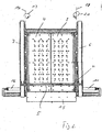
- FIG. 1 and 2 In general, an intermediate layer for table 1 is shown, which has two suction plates (2, 3), of which at least one of the suction plates (2, 3) is pivotable in a horizontal plane.
- Both arranged suction plates (2, 3) are pivotable in a horizontal plane.
- the suction plates 2, 3 are the same size and separated by a parting plane 13 from each other.
- Each suction plate 2, 3 has a number of suction nozzles 4, which may also be controlled separately.
- a Abschiebebalken 5 is arranged, which is driven displaceably in the direction of arrow 14 (Abschiebecardi) and in the opposite direction.
- the Abschiebebalken 5 at the two ends each fixed to a conveyor belt 6, 7, wherein each conveyor belt 6, 7 part of a belt conveyor 8.
- the Abschiebebalken is connected to a measuring device (not shown here), which depending on the measured value of the resistance when pushing the goods allows an assignment as a product or as an intermediate layer, since an intermediate layer forms a lower resistance compared to a product.
- the drive of the belt conveyor 8 with the two conveyor belts 6, 7 takes place by means of a drive 9 arranged below the table.
- each pivot cylinder is arranged at one end to the table and engages with its upper, piston-side end on the pivotable part of the respective suction plate 2, 3.
- each suction plate 2, 3 is pivoted into the pivot axis 17, 18 in the directions of arrows 19, 20, so that a kind of trap door results.
- a transition plate 15 is provided, with which the deported from the Abschiebebalken 5 in the direction of arrow 14 goods is conveyed to a subsequent conveyor system.
- FIG. 1 and 2 still shown that the goods are placed from above in the direction of arrow 16 on the surface of the suction plates 2, 3.
- FIG. 2 shows the top view of the arrangement FIG. 1
- FIG. 3 shows a practical application example, where it can be seen that the Abschiebebalken 5 is located in the forward position and on the intermediate separation table 1, a plurality of goods 21 are deposited, resting on an intermediate layer 22.
- the goods 21 are therefore promoted to a downstream belt system, while the intermediate layer 22 is held on the suction plates 2, 3.
- FIG. 5 open the two suction plates 2, 3 like a trap door in the Abschiebebalken 5 in the forward position and it can be seen that the intermediate layer 22 now falls due to the weight due to the resulting opening down.
- FIG. 6 shown, where it can be seen that the suction plates 2, 3 are completely open and the intermediate layer 22 has fallen down. It is important that the suction plate 2, 3 simultaneously form the lateral walls of a shaft and so at the same time form a guide for the intermediate layer 22 in the case down.
- the liner 22 is centered after dropped down and stacked under control in the lower area below the liner separator table 1.
Landscapes
- De-Stacking Of Articles (AREA)
- Sheets, Magazines, And Separation Thereof (AREA)
- Stacking Of Articles And Auxiliary Devices (AREA)
- Pallets (AREA)
Claims (11)
- Dispositif pour retirer des feuilles intermédiaires (22) entre des produits et des matériaux (21) palettisés, étant précisé que les produits et matériaux (21) sont placés sur la palette en étant superposés et présentent de préférence une feuille intermédiaire (22) entre les couches individuelles, laquelle feuille intermédiaire (22) est déposée par couches avec les produits et matériaux (21) sur un système de convoyeur qui sépare en série les produits et matériaux (21) déposés parallèlement, le système de convoyeur comportant un convoyeur à bande avec, comme table d'aspiration, une plate-forme d'aspiration (2, 3) qui immobilise à l'aide du vide la feuille intermédiaire (21), caractérisé en ce que la table d'aspiration se compose d'au moins deux plaques d'aspiration (2, 3) séparées, au moins une plaque d'aspiration (2, 3) étant apte à pivoter dans un plan horizontal à la manière d'une trappe.
- Dispositif selon la revendication 1, caractérisé en ce que les deux plaques d'aspiration (2, 3) ont à peu près la même taille et présentent un certain nombre de buses d'aspiration (4) aptes à être commandées séparément, les plaques d'aspiration (2, 3) étant séparées à l'aide d'un plan de séparation (13).
- Dispositif selon l'une des revendications 1 à 2 précédentes, caractérisé en ce qu'une barre pousseuse (5) disposée au-dessus de la plaque d'aspiration (2, 3) est apte à être entraînée pour coulisser dans le sens de la flèche (14) et en sens inverse, laquelle barre pousseuse (5) est reliée à deux bandes transporteuses (6, 7), chaque bande transporteuse (6, 7) faisant partie d'un convoyeur à bande (8) relié à un dynamomètre qui, en présence d'une valeur de mesure correspondante, assure une affectation des matériaux comme feuille intermédiaire ou comme produit.
- Dispositif selon l'une des revendications 1 à 3 précédentes, caractérisé en ce que la ou les plaques d'aspiration (2, 3) sont aptes à pivoter grâce à un vérin de pivotement (11, 12), chaque vérin de pivotement (11, 12) étant disposé à une extrémité de la table et agissant, à son extrémité supérieure située côté piston, sur la partie pivotante de la plaque d'aspiration (2, 3) correspondante.
- Dispositif selon l'une des revendications 1 à 4 précédentes, caractérisé en ce que le vérin de pivotement (11, 12) de la plaque d'aspiration (2, 3) est apte à pivoter respectivement dans le sens des flèches (19, 20) sur un axe de pivotement (17, 18), moyennant quoi ladite plaque d'aspiration (2, 3) est conçue comme une sorte de trappe.
- Dispositif selon l'une des revendications 1 à 5 précédentes, caractérisé en ce que la plaque d'aspiration (2, 3) présente à sa sortie une tôle de transition (15) qui amène sur un système de convoyeur prévu à la suite les matériaux (21) poussés dans le sens de la flèche (14) par la barre pousseuse (5), lesquels matériaux (21) sont au préalable déposés par le haut sur la surface des plaques d'aspiration (2, 3) dans le sens de la flèche (16).
- Dispositif selon l'une des revendications 1 à 6 précédentes, caractérisé en ce qu'un grand nombre de matériaux (21) est déposé sur une table de séparation de feuille intermédiaire (1), lesquels matériaux sont posés sur une feuille intermédiaire (22) quand la barre pousseuse (5) présente une position avant.
- Dispositif selon l'une des revendications 1 à 7 précédentes, caractérisé en ce que la plaque d'aspiration (2, 3) immobilise par aspiration la feuille intermédiaire (22) pendant que la barre pousseuse (5) se déplace dans le sens de poussée (14) sur ladite feuille intermédiaire (22).
- Dispositif selon l'une des revendications 1 à 8 précédentes, caractérisé en ce que la feuille intermédiaire (22) tombe vers le bas, par gravité, par une ouverture qui se forme, laquelle ouverture est formée par la ou les plaques d'aspiration (2, 3) qui s'ouvrent à la manière d'une trappe, la plaque d'aspiration (2, 3) ouverte formant une paroi qui définit un guidage pour la feuille intermédiaire (22) qui tombe, moyennant quoi les feuilles intermédiaires (22) sont empilées de manière commandée dans la zone inférieure de la table de séparation de feuille intermédiaire (1).
- Procédé pour retirer des feuilles intermédiaires entre des produits et des matériaux (21) palettisés, étant précisé que les produits et matériaux (21) sont placés sur la palette en étant superposés et présentent de préférence une feuille intermédiaire (22) entre les couches individuelles, laquelle feuille intermédiaire (22) est déposée par couches avec les produits et matériaux (21) sur un système de convoyeur qui sépare en série les produits et matériaux (21) déposés parallèlement, le système de convoyeur comportant un convoyeur à bande avec une plate-forme d'aspiration (2, 3) qui immobilise à l'aide du vide la feuille intermédiaire (21) pendant que les produits et matériaux (21) posés dessus sont expulsés de la feuille intermédiaire (22) à l'aide d'une barre pousseuse (5) dans le sens de transport du convoyeur à bande, et la feuille intermédiaire (22) est évacuée en sens inverse par rapport au sens de transport du convoyeur à bande à l'aide d'un convoyeur à aspiration à vide, caractérisé en ce que lors de l'étape pendant laquelle la feuille intermédiaire (22) se trouve sur la table d'aspiration (2, 3), la table d'aspiration (2, 3) est divisée en deux, au moins, et pivote vers le bas à la manière d'une trappe afin de laisser la feuille de papier intermédiaire (22) tomber vers le bas d'une manière définie.
- Procédé selon la revendication 10, qui comprend les étapes suivantes :a. dépôt, sur un système de convoyeur, d'une première couche de produits et matériaux (21) placés sur une palette, avec une feuille intermédiaire (22) disposée entre les couches individuelles,b. dépôt parallèle des produits et matériaux (21) sur un système de convoyeur,c. séparation en série des produits et matériaux (21)- aspiration de la feuille intermédiaire (22) à l'aide de buses d'aspiration (4) disposées sur les plaques d'aspiration (2, 3), sur le convoyeur à bande (8) du système de convoyeur ;- expulsion des produits et matériaux (21) disposés sur la feuille intermédiaire (22), à l'aide d'une barre pousseuse ;d. ouverture d'au moins une plaque d'aspiration (2, 3) par pivotement vers le bas ;e. empilage commandé, sous la table de séparation de feuille intermédiaire (1), des feuilles intermédiaires (22) qui tombent vers le bas.
Applications Claiming Priority (1)
| Application Number | Priority Date | Filing Date | Title |
|---|---|---|---|
| DE102007056826A DE102007056826A1 (de) | 2007-11-26 | 2007-11-26 | Verfahren und Vorrichtung zur Entfernung von Zwischenlagern von palettierten Waren und Gütern |
Publications (2)
| Publication Number | Publication Date |
|---|---|
| EP2062838A1 EP2062838A1 (fr) | 2009-05-27 |
| EP2062838B1 true EP2062838B1 (fr) | 2010-09-01 |
Family
ID=40225295
Family Applications (1)
| Application Number | Title | Priority Date | Filing Date |
|---|---|---|---|
| EP08020378A Active EP2062838B1 (fr) | 2007-11-26 | 2008-11-24 | Méthode et dispositif destinés au retrait de feuilles intermédiaires entre produits palettisés |
Country Status (4)
| Country | Link |
|---|---|
| EP (1) | EP2062838B1 (fr) |
| AT (1) | ATE479619T1 (fr) |
| DE (2) | DE102007056826A1 (fr) |
| ES (1) | ES2357298T3 (fr) |
Families Citing this family (3)
| Publication number | Priority date | Publication date | Assignee | Title |
|---|---|---|---|---|
| NL2006884C2 (nl) * | 2011-06-01 | 2012-12-04 | Vanderlande Ind Bv | Werkwijze en systeem voor het verwerken van een laag producten afkomstig van een pallet. |
| DE102016107384B4 (de) * | 2016-04-21 | 2019-11-21 | Martinmechanic Friedrich Martin Gmbh & Co. Kg | Entstapeleinrichtung zum lageweisen Entstapeln von Transportpaletten mit durch oder ohne durch Zwischenlagen getrennten Stapellagen |
| IT202200012140A1 (it) * | 2022-06-08 | 2023-12-08 | Flexlink Systems S P A | Dispositivo per il prelievo di prodotti impilati e metodo per prelevare prodotti impilati su pallet |
Family Cites Families (8)
| Publication number | Priority date | Publication date | Assignee | Title |
|---|---|---|---|---|
| DE1035572B (de) * | 1953-01-16 | 1958-07-31 | Fritz Ungerer Dipl Ing | Blechfoerderer fuer selbsttaetige Blechbandzerteilanlagen |
| NL6600462A (fr) * | 1966-01-13 | 1967-07-14 | ||
| DE2007113A1 (de) * | 1970-02-17 | 1971-09-02 | Ruhrtrans Internationale Befrach tungs und Transport GmbH & Co KG, 4630 Bochum | Anordnung zum Palettieren gefüllter Sacke |
| DE2222678C2 (de) * | 1972-05-09 | 1975-08-07 | Langguth & Co, Maschinenfabrik, 4400 Muenster | Entpalletieranlage für aus ferromagnetischem Werkstoff bestehende Behälter |
| US4787810A (en) * | 1987-09-04 | 1988-11-29 | Cawley Wesley D | Method and apparatus for handling stacks of loose sheet material |
| DE19515998C2 (de) * | 1995-05-02 | 1997-06-12 | Profinish Sa | Verfahren und Vorrichtung zum Depalettieren |
| DE102006019767A1 (de) * | 2006-04-28 | 2007-11-08 | Trumpf Werkzeugmaschinen Gmbh + Co. Kg | Verfahren und maschinelle Anordnung zum Handhaben eines Werkstücks mit zumindest einer Durchtrittsöffnung |
| US20080193272A1 (en) * | 2007-02-08 | 2008-08-14 | Sage Automation, Inc. | Process for depalletizing goods |
-
2007
- 2007-11-26 DE DE102007056826A patent/DE102007056826A1/de not_active Withdrawn
-
2008
- 2008-11-24 EP EP08020378A patent/EP2062838B1/fr active Active
- 2008-11-24 DE DE502008001247T patent/DE502008001247D1/de active Active
- 2008-11-24 ES ES08020378T patent/ES2357298T3/es active Active
- 2008-11-24 AT AT08020378T patent/ATE479619T1/de active
Also Published As
| Publication number | Publication date |
|---|---|
| DE502008001247D1 (de) | 2010-10-14 |
| ATE479619T1 (de) | 2010-09-15 |
| ES2357298T3 (es) | 2011-04-25 |
| DE102007056826A1 (de) | 2009-06-25 |
| EP2062838A1 (fr) | 2009-05-27 |
Similar Documents
| Publication | Publication Date | Title |
|---|---|---|
| DE2534819C2 (de) | Vorrichtung zum Entstapeln und Transportieren von Platinen | |
| EP2103556A1 (fr) | Dispositif de palettisation | |
| AT405640B (de) | Kommissionieranlage | |
| DE2952624A1 (de) | Vorrichtung zum gruppieren von gegenstaenden in stapelschichten zur beschickung von paletten | |
| EP4126719B1 (fr) | Procédé pour trier des articles et dispositif de tri | |
| EP0417503B1 (fr) | Procédé et dispositif pour le traitement ultérieur de produits imprimés empilés, de préférence pliés | |
| EP2062838B1 (fr) | Méthode et dispositif destinés au retrait de feuilles intermédiaires entre produits palettisés | |
| EP0713835B1 (fr) | Dispositif de palettisation | |
| DE2702724A1 (de) | Einrichtung zum sortieren und ablegen von zuschnitten bei plattenaufteilanlagen | |
| EP1389597B1 (fr) | Méthode et dispositif pour dépiler une pile d'articles disposés en plusieurs couches horizontales | |
| EP2918524A1 (fr) | Système destiné à désempiler manuellement et/ou à empiler des marchandises | |
| EP2176149B1 (fr) | Procédé de désempilement ou d'empilement de fûts | |
| DE2808948A1 (de) | Vorrichtung zum aufeinanderschichten von lagen aus papierbogen | |
| EP0465916B1 (fr) | Dispositif de convoyage pour unités en couches | |
| DE2831685A1 (de) | Zufuehrmechanismus fuer verpackungsmaterial | |
| EP1593633B1 (fr) | Dispositif pour empiler des articles imprimés | |
| DE102006058173A1 (de) | Vorrichtung zum Sortieren benutzter und in Stapeln gesammelter Paletten | |
| DE2558340C2 (de) | Vorrichtung zum Stapeln von blockförmigen Gütern | |
| DE10141964B4 (de) | Verfahren und Vorrichtung zum Stapeln von Riesen | |
| EP2243731A1 (fr) | Dispositif de palettisation d'articles par couches | |
| EP2323938B1 (fr) | Dispositif de collecte et de transport d'empilements formés de couches de feuilles | |
| DE4436075A1 (de) | Vorrichtung zum Palettieren von Stückgütern zu einem Stückgutstapel | |
| DE10302953B4 (de) | Abladeanordnung und Verfahren zum sortierten Abladen von in Format und/oder Aufdruck unterschiedlicher Lagen aus blattförmigen Materialien | |
| EP0870710A1 (fr) | Méthode et dispositif pour séparer et empiler du courant de transport des articles imprimés | |
| DE20220048U1 (de) | Vorrichtung zum schichtweisen Umsetzen von Behälterlagen |
Legal Events
| Date | Code | Title | Description |
|---|---|---|---|
| PUAI | Public reference made under article 153(3) epc to a published international application that has entered the european phase |
Free format text: ORIGINAL CODE: 0009012 |
|
| AK | Designated contracting states |
Kind code of ref document: A1 Designated state(s): AT BE BG CH CY CZ DE DK EE ES FI FR GB GR HR HU IE IS IT LI LT LU LV MC MT NL NO PL PT RO SE SI SK TR |
|
| AX | Request for extension of the european patent |
Extension state: AL BA MK RS |
|
| 17P | Request for examination filed |
Effective date: 20091111 |
|
| AKX | Designation fees paid |
Designated state(s): AT BE BG CH CY CZ DE DK EE ES FI FR GB GR HR HU IE IS IT LI LT LU LV MC MT NL NO PL PT RO SE SI SK TR |
|
| GRAP | Despatch of communication of intention to grant a patent |
Free format text: ORIGINAL CODE: EPIDOSNIGR1 |
|
| GRAS | Grant fee paid |
Free format text: ORIGINAL CODE: EPIDOSNIGR3 |
|
| GRAA | (expected) grant |
Free format text: ORIGINAL CODE: 0009210 |
|
| AK | Designated contracting states |
Kind code of ref document: B1 Designated state(s): AT BE BG CH CY CZ DE DK EE ES FI FR GB GR HR HU IE IS IT LI LT LU LV MC MT NL NO PL PT RO SE SI SK TR |
|
| REG | Reference to a national code |
Ref country code: GB Ref legal event code: FG4D Free format text: NOT ENGLISH |
|
| REG | Reference to a national code |
Ref country code: CH Ref legal event code: EP |
|
| REG | Reference to a national code |
Ref country code: IE Ref legal event code: FG4D Free format text: LANGUAGE OF EP DOCUMENT: GERMAN |
|
| REF | Corresponds to: |
Ref document number: 502008001247 Country of ref document: DE Date of ref document: 20101014 Kind code of ref document: P |
|
| REG | Reference to a national code |
Ref country code: NL Ref legal event code: T3 |
|
| PG25 | Lapsed in a contracting state [announced via postgrant information from national office to epo] |
Ref country code: NO Free format text: LAPSE BECAUSE OF FAILURE TO SUBMIT A TRANSLATION OF THE DESCRIPTION OR TO PAY THE FEE WITHIN THE PRESCRIBED TIME-LIMIT Effective date: 20101201 Ref country code: LT Free format text: LAPSE BECAUSE OF FAILURE TO SUBMIT A TRANSLATION OF THE DESCRIPTION OR TO PAY THE FEE WITHIN THE PRESCRIBED TIME-LIMIT Effective date: 20100901 Ref country code: FI Free format text: LAPSE BECAUSE OF FAILURE TO SUBMIT A TRANSLATION OF THE DESCRIPTION OR TO PAY THE FEE WITHIN THE PRESCRIBED TIME-LIMIT Effective date: 20100901 |
|
| LTIE | Lt: invalidation of european patent or patent extension |
Effective date: 20100901 |
|
| PG25 | Lapsed in a contracting state [announced via postgrant information from national office to epo] |
Ref country code: PL Free format text: LAPSE BECAUSE OF FAILURE TO SUBMIT A TRANSLATION OF THE DESCRIPTION OR TO PAY THE FEE WITHIN THE PRESCRIBED TIME-LIMIT Effective date: 20100901 Ref country code: SI Free format text: LAPSE BECAUSE OF FAILURE TO SUBMIT A TRANSLATION OF THE DESCRIPTION OR TO PAY THE FEE WITHIN THE PRESCRIBED TIME-LIMIT Effective date: 20100901 Ref country code: CY Free format text: LAPSE BECAUSE OF FAILURE TO SUBMIT A TRANSLATION OF THE DESCRIPTION OR TO PAY THE FEE WITHIN THE PRESCRIBED TIME-LIMIT Effective date: 20100901 Ref country code: HR Free format text: LAPSE BECAUSE OF FAILURE TO SUBMIT A TRANSLATION OF THE DESCRIPTION OR TO PAY THE FEE WITHIN THE PRESCRIBED TIME-LIMIT Effective date: 20100901 |
|
| REG | Reference to a national code |
Ref country code: IE Ref legal event code: FD4D |
|
| PG25 | Lapsed in a contracting state [announced via postgrant information from national office to epo] |
Ref country code: LV Free format text: LAPSE BECAUSE OF FAILURE TO SUBMIT A TRANSLATION OF THE DESCRIPTION OR TO PAY THE FEE WITHIN THE PRESCRIBED TIME-LIMIT Effective date: 20100901 Ref country code: SE Free format text: LAPSE BECAUSE OF FAILURE TO SUBMIT A TRANSLATION OF THE DESCRIPTION OR TO PAY THE FEE WITHIN THE PRESCRIBED TIME-LIMIT Effective date: 20100901 Ref country code: GR Free format text: LAPSE BECAUSE OF FAILURE TO SUBMIT A TRANSLATION OF THE DESCRIPTION OR TO PAY THE FEE WITHIN THE PRESCRIBED TIME-LIMIT Effective date: 20101202 |
|
| REG | Reference to a national code |
Ref country code: CH Ref legal event code: NV Representative=s name: LUCHS & PARTNER AG PATENTANWAELTE |
|
| REG | Reference to a national code |
Ref country code: ES Ref legal event code: FG2A Ref document number: 2357298 Country of ref document: ES Kind code of ref document: T3 Effective date: 20110425 |
|
| PG25 | Lapsed in a contracting state [announced via postgrant information from national office to epo] |
Ref country code: IE Free format text: LAPSE BECAUSE OF FAILURE TO SUBMIT A TRANSLATION OF THE DESCRIPTION OR TO PAY THE FEE WITHIN THE PRESCRIBED TIME-LIMIT Effective date: 20100901 |
|
| BERE | Be: lapsed |
Owner name: FPT PROJEKT G.M.B.H. Effective date: 20101130 |
|
| PG25 | Lapsed in a contracting state [announced via postgrant information from national office to epo] |
Ref country code: IT Free format text: LAPSE BECAUSE OF FAILURE TO SUBMIT A TRANSLATION OF THE DESCRIPTION OR TO PAY THE FEE WITHIN THE PRESCRIBED TIME-LIMIT Effective date: 20100901 Ref country code: CZ Free format text: LAPSE BECAUSE OF FAILURE TO SUBMIT A TRANSLATION OF THE DESCRIPTION OR TO PAY THE FEE WITHIN THE PRESCRIBED TIME-LIMIT Effective date: 20100901 Ref country code: EE Free format text: LAPSE BECAUSE OF FAILURE TO SUBMIT A TRANSLATION OF THE DESCRIPTION OR TO PAY THE FEE WITHIN THE PRESCRIBED TIME-LIMIT Effective date: 20100901 Ref country code: IS Free format text: LAPSE BECAUSE OF FAILURE TO SUBMIT A TRANSLATION OF THE DESCRIPTION OR TO PAY THE FEE WITHIN THE PRESCRIBED TIME-LIMIT Effective date: 20110101 Ref country code: RO Free format text: LAPSE BECAUSE OF FAILURE TO SUBMIT A TRANSLATION OF THE DESCRIPTION OR TO PAY THE FEE WITHIN THE PRESCRIBED TIME-LIMIT Effective date: 20100901 Ref country code: PT Free format text: LAPSE BECAUSE OF FAILURE TO SUBMIT A TRANSLATION OF THE DESCRIPTION OR TO PAY THE FEE WITHIN THE PRESCRIBED TIME-LIMIT Effective date: 20110103 Ref country code: SK Free format text: LAPSE BECAUSE OF FAILURE TO SUBMIT A TRANSLATION OF THE DESCRIPTION OR TO PAY THE FEE WITHIN THE PRESCRIBED TIME-LIMIT Effective date: 20100901 |
|
| PG25 | Lapsed in a contracting state [announced via postgrant information from national office to epo] |
Ref country code: MC Free format text: LAPSE BECAUSE OF NON-PAYMENT OF DUE FEES Effective date: 20101130 |
|
| PLBE | No opposition filed within time limit |
Free format text: ORIGINAL CODE: 0009261 |
|
| STAA | Information on the status of an ep patent application or granted ep patent |
Free format text: STATUS: NO OPPOSITION FILED WITHIN TIME LIMIT |
|
| 26N | No opposition filed |
Effective date: 20110606 |
|
| PG25 | Lapsed in a contracting state [announced via postgrant information from national office to epo] |
Ref country code: BE Free format text: LAPSE BECAUSE OF NON-PAYMENT OF DUE FEES Effective date: 20101130 Ref country code: DK Free format text: LAPSE BECAUSE OF FAILURE TO SUBMIT A TRANSLATION OF THE DESCRIPTION OR TO PAY THE FEE WITHIN THE PRESCRIBED TIME-LIMIT Effective date: 20100901 |
|
| REG | Reference to a national code |
Ref country code: DE Ref legal event code: R097 Ref document number: 502008001247 Country of ref document: DE Effective date: 20110606 |
|
| PG25 | Lapsed in a contracting state [announced via postgrant information from national office to epo] |
Ref country code: MT Free format text: LAPSE BECAUSE OF FAILURE TO SUBMIT A TRANSLATION OF THE DESCRIPTION OR TO PAY THE FEE WITHIN THE PRESCRIBED TIME-LIMIT Effective date: 20100901 |
|
| PG25 | Lapsed in a contracting state [announced via postgrant information from national office to epo] |
Ref country code: LU Free format text: LAPSE BECAUSE OF NON-PAYMENT OF DUE FEES Effective date: 20101124 Ref country code: BG Free format text: LAPSE BECAUSE OF FAILURE TO SUBMIT A TRANSLATION OF THE DESCRIPTION OR TO PAY THE FEE WITHIN THE PRESCRIBED TIME-LIMIT Effective date: 20100901 Ref country code: HU Free format text: LAPSE BECAUSE OF FAILURE TO SUBMIT A TRANSLATION OF THE DESCRIPTION OR TO PAY THE FEE WITHIN THE PRESCRIBED TIME-LIMIT Effective date: 20110302 |
|
| PG25 | Lapsed in a contracting state [announced via postgrant information from national office to epo] |
Ref country code: TR Free format text: LAPSE BECAUSE OF FAILURE TO SUBMIT A TRANSLATION OF THE DESCRIPTION OR TO PAY THE FEE WITHIN THE PRESCRIBED TIME-LIMIT Effective date: 20100901 |
|
| PG25 | Lapsed in a contracting state [announced via postgrant information from national office to epo] |
Ref country code: BG Free format text: LAPSE BECAUSE OF FAILURE TO SUBMIT A TRANSLATION OF THE DESCRIPTION OR TO PAY THE FEE WITHIN THE PRESCRIBED TIME-LIMIT Effective date: 20101201 |
|
| REG | Reference to a national code |
Ref country code: FR Ref legal event code: PLFP Year of fee payment: 8 |
|
| REG | Reference to a national code |
Ref country code: FR Ref legal event code: PLFP Year of fee payment: 9 |
|
| REG | Reference to a national code |
Ref country code: FR Ref legal event code: PLFP Year of fee payment: 10 |
|
| PGFP | Annual fee paid to national office [announced via postgrant information from national office to epo] |
Ref country code: NL Payment date: 20231122 Year of fee payment: 16 |
|
| PGFP | Annual fee paid to national office [announced via postgrant information from national office to epo] |
Ref country code: GB Payment date: 20231123 Year of fee payment: 16 |
|
| PGFP | Annual fee paid to national office [announced via postgrant information from national office to epo] |
Ref country code: ES Payment date: 20231215 Year of fee payment: 16 |
|
| PGFP | Annual fee paid to national office [announced via postgrant information from national office to epo] |
Ref country code: FR Payment date: 20231122 Year of fee payment: 16 Ref country code: DE Payment date: 20231120 Year of fee payment: 16 Ref country code: CH Payment date: 20231202 Year of fee payment: 16 Ref country code: AT Payment date: 20231117 Year of fee payment: 16 |