EP2062838B1 - Method and device for removing intermediate sheet between palletised goods - Google Patents
Method and device for removing intermediate sheet between palletised goods Download PDFInfo
- Publication number
- EP2062838B1 EP2062838B1 EP08020378A EP08020378A EP2062838B1 EP 2062838 B1 EP2062838 B1 EP 2062838B1 EP 08020378 A EP08020378 A EP 08020378A EP 08020378 A EP08020378 A EP 08020378A EP 2062838 B1 EP2062838 B1 EP 2062838B1
- Authority
- EP
- European Patent Office
- Prior art keywords
- goods
- intermediate layer
- suction
- commodities
- vacuum
- Prior art date
- Legal status (The legal status is an assumption and is not a legal conclusion. Google has not performed a legal analysis and makes no representation as to the accuracy of the status listed.)
- Active
Links
- 238000000034 method Methods 0.000 title claims abstract description 10
- 238000000926 separation method Methods 0.000 claims description 7
- 230000007704 transition Effects 0.000 claims description 4
- 230000005484 gravity Effects 0.000 claims 1
- 238000005259 measurement Methods 0.000 claims 1
- 239000002184 metal Substances 0.000 claims 1
- 239000010410 layer Substances 0.000 description 49
- 230000007246 mechanism Effects 0.000 description 5
- 230000008021 deposition Effects 0.000 description 2
- 230000008014 freezing Effects 0.000 description 2
- 238000007710 freezing Methods 0.000 description 2
- 230000000284 resting effect Effects 0.000 description 2
- 241000531116 Blitum bonus-henricus Species 0.000 description 1
- 235000008645 Chenopodium bonus henricus Nutrition 0.000 description 1
- 230000001154 acute effect Effects 0.000 description 1
- 230000006835 compression Effects 0.000 description 1
- 238000007906 compression Methods 0.000 description 1
- 239000004744 fabric Substances 0.000 description 1
- 239000011229 interlayer Substances 0.000 description 1
- 238000012423 maintenance Methods 0.000 description 1
- 230000014759 maintenance of location Effects 0.000 description 1
- 238000004519 manufacturing process Methods 0.000 description 1
- 230000000717 retained effect Effects 0.000 description 1
Images


Classifications
-
- B—PERFORMING OPERATIONS; TRANSPORTING
- B65—CONVEYING; PACKING; STORING; HANDLING THIN OR FILAMENTARY MATERIAL
- B65G—TRANSPORT OR STORAGE DEVICES, e.g. CONVEYORS FOR LOADING OR TIPPING, SHOP CONVEYOR SYSTEMS OR PNEUMATIC TUBE CONVEYORS
- B65G59/00—De-stacking of articles
- B65G59/005—De-stacking of articles by using insertions or spacers between the stacked layers
Definitions
- the subject matter of the present invention is a method and a device for removing intermediate layers of palletized goods and goods according to the preamble of patent claim 1.
- the goods taken upwards from the pallet by means of a suction gripper are then placed on a conveyor system which is able to serially separate the goods set in parallel on a conveyor system.
- the intermediate layer remains on the belt conveyor and the goods stored thereon are moved away with the Abschiebebalken.
- Another disadvantage is that a relatively expensive vacuum-assisted belt conveyor must be used, which leads to high manufacturing and maintenance costs.
- the invention is therefore based on the object, a method and an apparatus of the type mentioned in such a way that with much simpler means, more cost-effective and faster defined an intermediate layer can be separated from an overlying layer of goods.
- a method is characterized in that in the process step in which the intermediate layer rests on the suction table, the suction table is at least halved and folds down in the manner of a flap door to let the liner paper fall down defined.
- the vacuum table has two symmetrical vacuum plates and in the middle between the vacuum plates a dividing line is present, so that exactly the two vacuum plates in the manner of a trap door open downward.
- the central separating gap thus widens to a large-sized fürfallö réelle through which the liner paper weight falls down and falls into a shaft located there underneath and aligns there and stacked one above the other.
- this dividing line is perpendicular to the direction of movement of the Abschiebebalkens.
- the present invention is not limited to that the storage area for the storage of the intermediate layer works on a suction principle.
- other retaining mechanisms are used instead of the suction principle, with which the intermediate paper is held.
- Such retention mechanisms are e.g. a needle gripper having acute obliquely engaging in the position of the intermediate layer needles so as to hold this intermediate position. If the needles are withdrawn, then the intermediate layer is defined on this needle table, and it is then also provided that this needle table is designed as a trap door mechanism, so that when retracting the needles, the trap door is opened and the intermediate layer is placed vertically down due to weight.
- the basic principle of the present invention lies essentially in the fact that with the Abschiebebalken the goods to be separated from the interlayer deported so that you can push off the goods on the intermediate layer, which is held by the underlying holding table. It is relatively indifferent, which holding mechanism one uses, it is only important that the holding force for the liner is chosen so large that when you push the goods, the liner is not deported. For this reason, therefore, the plate on which the intermediate layer is formed as a suction plate, a needle plate or freeze gripper plate.
- Such a freeze gripper plate consists essentially of a number of uniformly distributed over the table arranged freeze grippers, which temporarily produce an ice sheet on the underside of the intermediate layer below the freezing temperature and thus hold the intermediate layer.
- the present invention relates to all the palletizing, in which a product is lifted in layers from a pallet and wherein the layered goods are separated by respective intermediate layers.
- the vacuum nozzles arranged in the table are controlled, depending on the area of the goods deposited on the table.
- the nozzles can be arranged in the conveying direction in bar form, for example, wherein in the conveying direction column-shaped nozzles are arranged, and each column can be switched on and off. In this way it is possible to shut down, for example, the left and right extreme column, if it turns out that the occupation area of the table is given only in the middle.
- the nozzles can be switched off line by line and column by column, and in another embodiment it is possible to individually control the nozzles and turn them on or off.
- FIG. 1 and 2 In general, an intermediate layer for table 1 is shown, which has two suction plates (2, 3), of which at least one of the suction plates (2, 3) is pivotable in a horizontal plane.
- Both arranged suction plates (2, 3) are pivotable in a horizontal plane.
- the suction plates 2, 3 are the same size and separated by a parting plane 13 from each other.
- Each suction plate 2, 3 has a number of suction nozzles 4, which may also be controlled separately.
- a Abschiebebalken 5 is arranged, which is driven displaceably in the direction of arrow 14 (Abschiebecardi) and in the opposite direction.
- the Abschiebebalken 5 at the two ends each fixed to a conveyor belt 6, 7, wherein each conveyor belt 6, 7 part of a belt conveyor 8.
- the Abschiebebalken is connected to a measuring device (not shown here), which depending on the measured value of the resistance when pushing the goods allows an assignment as a product or as an intermediate layer, since an intermediate layer forms a lower resistance compared to a product.
- the drive of the belt conveyor 8 with the two conveyor belts 6, 7 takes place by means of a drive 9 arranged below the table.
- each pivot cylinder is arranged at one end to the table and engages with its upper, piston-side end on the pivotable part of the respective suction plate 2, 3.
- each suction plate 2, 3 is pivoted into the pivot axis 17, 18 in the directions of arrows 19, 20, so that a kind of trap door results.
- a transition plate 15 is provided, with which the deported from the Abschiebebalken 5 in the direction of arrow 14 goods is conveyed to a subsequent conveyor system.
- FIG. 1 and 2 still shown that the goods are placed from above in the direction of arrow 16 on the surface of the suction plates 2, 3.
- FIG. 2 shows the top view of the arrangement FIG. 1
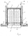
- FIG. 3 shows a practical application example, where it can be seen that the Abschiebebalken 5 is located in the forward position and on the intermediate separation table 1, a plurality of goods 21 are deposited, resting on an intermediate layer 22.
- the goods 21 are therefore promoted to a downstream belt system, while the intermediate layer 22 is held on the suction plates 2, 3.
- FIG. 5 open the two suction plates 2, 3 like a trap door in the Abschiebebalken 5 in the forward position and it can be seen that the intermediate layer 22 now falls due to the weight due to the resulting opening down.
- FIG. 6 shown, where it can be seen that the suction plates 2, 3 are completely open and the intermediate layer 22 has fallen down. It is important that the suction plate 2, 3 simultaneously form the lateral walls of a shaft and so at the same time form a guide for the intermediate layer 22 in the case down.
- the liner 22 is centered after dropped down and stacked under control in the lower area below the liner separator table 1.
Abstract
Description
Gegenstand der vorliegenden Erfindung ist ein Verfahren und eine Vorrichtung zur Entfernung von Zwischenlagen von palettierten Waren und Gütern nach dem Oberbegriff des Patentanspruches 1.The subject matter of the present invention is a method and a device for removing intermediate layers of palletized goods and goods according to the preamble of
Es ist z.B aus dem
Die mittels eines Sauggreifers nach oben von der Palette entnommenen Güter werden dann auf ein Fördersystem gesetzt, welches in der Lage ist, die parallel auf ein Fördersystem gesetzten Güter seriell zu vereinzeln.The goods taken upwards from the pallet by means of a suction gripper are then placed on a conveyor system which is able to serially separate the goods set in parallel on a conveyor system.
Bei der Entfernung der Zwischenlage gibt es die bekannte Möglichkeit, dass die schichtweise abgehobene Lage von Gütern auf eine Saugplattform gelegt wird, und diese Saugplattform hat vakuumunterstützte Gurtförderer. Es ist ein Abschieber vorhanden, der in der Lage ist, alle Waren über diese Saugplattform hinwegzuschieben.When removing the liner, there is the well-known possibility that the layer-by-layer attitude of goods is placed on a suction platform, and this suction platform has vacuum-assisted belt conveyors. There is a pusher that is able to move all goods over this suction platform.
Für eine Anwendung ist es bekannt, die Waren von oben auf die Saugplattform mit dem saugunterstützten Gurtförderer zu stellen, wobei die zu entfernende Zwischenlage direkt auf die Oberfläche des saugunterstützten Gurtförderers gelangt. Es wird sodann Vakuum an den Gurtförderer angelegt, und die Zwischenlage wird dank dieses Vakuums auf der Saugplattform festgehalten, während die auf der Zwischenlage lagernden Güter mit dem Abschiebebalken über diese Saugplattform abgeschoben werden.For an application, it is known to place the goods from above onto the suction platform with the suction-assisted belt conveyor, whereby the intermediate layer to be removed passes directly onto the surface of the suction-assisted belt conveyor. It is then applied vacuum to the belt conveyor, and the liner is held thanks to this vacuum on the suction platform, while the goods stored on the intermediate layer goods are deported with the Abschiebebalken about this suction platform.
Im abgeschobenen Zustand verbleibt deshalb die Zwischenlage auf dem Gurtförderer und die darauf lagernden Güter werden mit dem Abschiebebalken wegbewegt.In the de-stowed state, therefore, the intermediate layer remains on the belt conveyor and the goods stored thereon are moved away with the Abschiebebalken.
Es wird dann der vakuumunterstützte Saugförderer in Betrieb genommen und das auf ihm festgesaugte Papier in Gegenrichtung zur Abschiebebewegung nach hinten wegtransportiert.It is then taken the vacuum-assisted suction conveyor in operation and transported sucked on him paper in the opposite direction to the Abschiebebewegung backwards.
Bei dieser bekannten Entfernung einer Zwischenlage besteht allerdings der Nachteil, dass die Zwischenlage nur relativ undefiniert entfernt werden kann, denn sie wird in Richtung nach hinten entfernt, und zwar in gleicher Ebene, wie der Saugförderer arbeitet. Weil dieses Zwischenlagepapier bei angetriebenem Saugförderer nach hinten abtransportiert wird, bekommt es eine gewisse Relativgeschwindigkeit - wegen der Geschwindigkeit des Saugförderers - und beim Abheben vom Saugförderer segelt es zu Boden, was zu undefinierten Landungen der Zwischenlage führt. Es kommt deshalb zu einem undefinierten Ablegen des Zwischenlagepapiers, und damit besteht der Nachteil, dass dieses Zwischenlagepapier einen relativ hohen Platzbedarf beim Ablagern hat.In this known removal of an intermediate layer, however, there is the disadvantage that the intermediate layer can be removed only relatively undefined, because it is removed in the backward direction, in the same plane as the suction conveyor works. Because this liner paper is transported to the rear with a driven suction conveyor, it gets a certain relative speed - because of the speed of the suction conveyor - and when lifted from the suction conveyor it sails to the ground, resulting in undefined landings of the liner. It therefore comes to an undefined deposition of the liner paper, and thus there is the disadvantage that this liner paper has a relatively high footprint in the deposition.
Weiterer Nachteil ist, dass ein relativ teurer vakuumunterstützter Gurtförderer verwendet werden muss, was zu hohen Herstellungs- und Wartungskosten führt.Another disadvantage is that a relatively expensive vacuum-assisted belt conveyor must be used, which leads to high manufacturing and maintenance costs.
Der Erfindung liegt deshalb die Aufgabe zugrunde, ein Verfahren und eine Vorrichtung der eingangs genannten Art so weiterzubilden, dass mit wesentlich einfacheren Mitteln, kostengünstiger und schneller eine Zwischenlage definiert von einer darüber lagernden Warenschicht abgetrennt werden kann.The invention is therefore based on the object, a method and an apparatus of the type mentioned in such a way that with much simpler means, more cost-effective and faster defined an intermediate layer can be separated from an overlying layer of goods.
Zur Lösung der gestellten Aufgabe ist ein Verfahren dadurch gekennzeichnet, dass in dem Verfahrensschritt, bei dem die Zwischenlage auf dem Saugtisch aufliegt, der Saugtisch mindestens halbiert ist und in der Art einer Klapptür nach unten wegklappt, um das Zwischenlagepapier definiert nach unten abfallen zu lassen.To achieve the object, a method is characterized in that in the process step in which the intermediate layer rests on the suction table, the suction table is at least halved and folds down in the manner of a flap door to let the liner paper fall down defined.
Mit der gegebenen technischen Lehre ergibt sich der wesentliche Vorteil, dass auf einen vakuumunterstützten Förderer verzichtet werden kann und dass vor allem der Nachteil entfällt, dass der Förderer das Papier in Förderrichtung transportieren muss, wodurch es eine Längsgeschwindigkeit erhält und undefiniert zu Boden segelt.With the given technical teaching, there is the significant advantage that can be dispensed with a vacuum-assisted conveyor and that especially eliminates the disadvantage that the conveyor must transport the paper in the conveying direction, whereby it receives a longitudinal speed and sails undefined to the ground.
Bei der vorliegenden Erfindung wird vielmehr eine Art Klapptür oder Falttür geöffnet, und die Zwischenlage fällt gewichtsbedingt gerade und unbeschleunigt und durch keinerlei Fördermechanismen beeinflusst nach unten in einen Schacht, wo es definiert abgelegt wird.In the present invention, rather, a kind of hinged door or folding door is opened, and the intermediate layer falls by weight straight and unaccelerated and influenced by any conveyor mechanisms down into a shaft, where it is stored defined.
Damit ergibt sich der wesentliche Vorteil, dass nun durch die definierte Ablage der Zwischenlage eine sehr gute Stapelung und Verdichtung aller Zwischenlagen möglich ist, weil diese genau definiert übereinandergelegt einen sehr komprimierten Stapel bilden. Es können deshalb eine Vielzahl von Zwischenlagen auf einem sehr engen Platzbedarf gestapelt werden. Damit können also sehr viele Zwischenlagen auf engem Raum gestapelt werden, und der Ablageraum für die Zwischenlagen ist sehr platzsparend direkt unterhalb dem Vakuumtisch angeordnet und nicht mehr neben oder seitlich des Vakuumtisches, wie es beim Stand der Technik der Fall war.This results in the significant advantage that a very good stacking and compression of all intermediate layers is now possible by the defined storage of the intermediate layer, because these define exactly defined superimposed form a very compressed stack. It can therefore be stacked a variety of liners in a very small footprint. So that many interleaves can be stacked in a small space, and the storage space for the intermediate layers is very space-saving directly below the vacuum table and no longer next to or side of the vacuum table, as was the case in the prior art.
In einer bevorzugten Ausgestaltung der vorliegenden Erfindung wird es bevorzugt, wenn der Vakuumtisch zwei symmetrische Vakuumplatten aufweist und in der Mitte zwischen den Vakuumplatten eine Trennlinie vorhanden ist, so dass genau die beiden Vakuumplatten in der Art einer Falltür sich nach unten liegend öffnen. Der mittige Trennspalt erweitert sich so zu einer groß dimensionierten Durchfallöffnung, durch welche das Zwischenlagepapier gewichtsbedingt herunterfällt und in einen dort darunter angeordneten Schacht hineinfällt und sich dort ausrichtet und stapelweise übereinander ablegt.In a preferred embodiment of the present invention, it is preferred if the vacuum table has two symmetrical vacuum plates and in the middle between the vacuum plates a dividing line is present, so that exactly the two vacuum plates in the manner of a trap door open downward. The central separating gap thus widens to a large-sized Durchfallöffnung through which the liner paper weight falls down and falls into a shaft located there underneath and aligns there and stacked one above the other.
Statt der Ausbildung einer Trennlinie parallel zur Förderrichtung des Abschiebebalkens ist es in einer anderen Ausgestaltung der Erfindung vorgesehen, dass diese Trennlinie senkrecht zur Bewegungsrichtung des Abschiebebalkens verläuft.Instead of forming a dividing line parallel to the conveying direction of the Abschiebebalkens, it is provided in another embodiment of the invention that this dividing line is perpendicular to the direction of movement of the Abschiebebalkens.
In einer dritten Ausgestaltung kann es vorgesehen werden, dass anstatt zwei schwenkbar ausgebildeten Vakuumplatten auch mehr als zwei schwenkbare Vakuumplatten angeordnet sind, z. B. drei oder mehrere.In a third embodiment, it may be provided that instead of two pivotally formed vacuum plates and more than two pivotable vacuum plates are arranged, for. B. three or more.
Die vorliegende Erfindung ist nicht darauf beschränkt, dass die Ablagefläche für die Ablage der Zwischenlage auf einem Saugprinzip arbeitet. In einer anderen Ausgestaltung der Erfindung kann es vorgesehen sein, dass statt des Saugprinzips, mit dem das Zwischenlagepapier festgehalten wird, auch andere Festhaltemechanismen verwendet werden. Solche Festhaltemechanismen sind z.B. ein Nadelgreifer, der spitz schräg in die Lage der Zwischenlage eingreifende Nadeln aufweist, um so diese Zwischenlage festzuhalten. Werden die Nadeln zurückgezogen, dann liegt die Zwischenlage definiert auf diesem Nadeltisch, und es ist dann ebenfalls vorgesehen, dass dieser Nadeltisch als Falltürmechanismus ausgebildet ist, so dass beim Zurückziehen der Nadeln die Falltür geöffnet und die Zwischenlage gewichtsbedingt vertikal nach unten abgelegt wird.The present invention is not limited to that the storage area for the storage of the intermediate layer works on a suction principle. In another embodiment of the invention, it may be provided that instead of the suction principle, with which the intermediate paper is held, other retaining mechanisms are used. Such retention mechanisms are e.g. a needle gripper having acute obliquely engaging in the position of the intermediate layer needles so as to hold this intermediate position. If the needles are withdrawn, then the intermediate layer is defined on this needle table, and it is then also provided that this needle table is designed as a trap door mechanism, so that when retracting the needles, the trap door is opened and the intermediate layer is placed vertically down due to weight.
Das Grundprinzip der vorliegenden Erfindung liegt im Wesentlichen darin, dass man mit dem Abschiebebalken die von der Zwischenlage zu trennenden Güter so abschiebt, dass man die Güter über die Zwischenlage abschieben kann, die von dem darunter liegenden Haltetisch festgehalten wird. Hierbei ist es relativ gleichgültig, welchen Haltemechanismus man verwendet, es ist nur wichtig, dass die Haltekraft für die Zwischenlage so groß gewählt ist, dass beim Abschieben der Güter die Zwischenlage nicht mit abgeschoben wird. Aus diesem Grund kann deshalb die Platte, auf der die Zwischenlage liegt, als Saugplatte, als Nadelplatte oder auch Gefriergreiferplatte ausgebildet sein.The basic principle of the present invention lies essentially in the fact that with the Abschiebebalken the goods to be separated from the interlayer deported so that you can push off the goods on the intermediate layer, which is held by the underlying holding table. It is relatively indifferent, which holding mechanism one uses, it is only important that the holding force for the liner is chosen so large that when you push the goods, the liner is not deported. For this reason, therefore, the plate on which the intermediate layer is formed as a suction plate, a needle plate or freeze gripper plate.
Eine solche Gefriergreiferplatte besteht im Wesentlichen aus einer Anzahl von gleichmäßig über den Tisch verteilt angeordneten Gefriergreifern, die unterhalb der Gefriertemperatur einen Eispanzer an der Unterseite der Zwischenlage temporär erzeugen und so die Zwischenlage festhalten. Sobald die Ware über die Zwischenlage abgeschoben ist, wird die Gefriertemperatur gelöst und die Vereisung an der Unterseite der Zwischenlage entfernt, wodurch dann wiederum durch das beschriebene Falltürprinzip die Zwischenlage gesteuert vertikal nach unten in einen unterhalb des Tisches angeordneten Schacht hineinfällt.Such a freeze gripper plate consists essentially of a number of uniformly distributed over the table arranged freeze grippers, which temporarily produce an ice sheet on the underside of the intermediate layer below the freezing temperature and thus hold the intermediate layer. Once the product has been deported through the intermediate layer, the freezing temperature is released and the icing removed on the underside of the intermediate layer, which then in turn by the described trapdoor principle, the intermediate layer controlled vertically falls down into a below the table arranged shaft.
Demzufolge bezieht sich die vorliegende Erfindung auf alle die Palettiereinrichtungen, bei denen eine Ware schichtweise von einer Palette abgehoben wird und wobei die schichtweise angeordneten Waren durch jeweils Zwischenlagen voneinander getrennt sind.Accordingly, the present invention relates to all the palletizing, in which a product is lifted in layers from a pallet and wherein the layered goods are separated by respective intermediate layers.
In einer Weiterbildung der vorliegenden Erfindung ist es im Übrigen vorgesehen, dass - bei der Ausbildung des Tisches mit Falltür als Saugtisch - dafür gesorgt ist, dass ein möglichst geringer Vakuumverbrauch gegeben ist.In one embodiment of the present invention, it is also provided that - in the design of the table with trap door as a suction table - it is ensured that the lowest possible vacuum consumption is given.
Zu diesem Zweck ist vorgesehen, dass die im Tisch angeordneten Unterdruckdüsen gesteuert sind, und zwar in Abhängigkeit von der Fläche der auf den Tisch abgesetzten Güter. Es erfolgt also eine Steuerung der Düsen in Abhängigkeit vom Belegungsgrad des Saugtisches. Hierbei gibt es verschiedene Möglichkeiten, die Düsenzuführung zu steuern. Die Düsen können beispielsweise in Förderrichtung in Balkenform angeordnet werden, wobei in Förderrichtung spaltenförmige Düsen angeordnet sind, und jede Spalte kann ein- und ausgeschaltet werden. Auf diese Weise ist es möglich, beispielsweise die linke und rechte äußerste Spalte stillzulegen, wenn sich herausstellt, dass die Belegungsfläche des Tisches nur in der Mitte gegeben ist.For this purpose, it is provided that the vacuum nozzles arranged in the table are controlled, depending on the area of the goods deposited on the table. Thus, there is a control of the nozzles depending on the degree of occupancy of the suction table. There are several ways to control the nozzle feed. The nozzles can be arranged in the conveying direction in bar form, for example, wherein in the conveying direction column-shaped nozzles are arranged, and each column can be switched on and off. In this way it is possible to shut down, for example, the left and right extreme column, if it turns out that the occupation area of the table is given only in the middle.
Dass heißt, die Düsen können zeilen- und spaltenweise abgeschaltet werden, und in einer anderen Ausgestaltung ist es möglich, die Düsen auch einzeln anzusteuern und einzuschalten oder abzuschalten.That is, the nozzles can be switched off line by line and column by column, and in another embodiment it is possible to individually control the nozzles and turn them on or off.
Der Erfindungsgegenstand der vorliegenden Erfindung ergibt sich nicht nur aus dem Gegenstand der einzelnen Patentansprüche, sondern auch aus der Kombination der einzelnen Patentansprüche untereinander.The subject of the present invention results not only from the subject matter of the individual claims, but also from the combination of the individual claims with each other.
Im Folgenden wird die Erfindung anhand von lediglich einen Ausführungsweg darstellenden Zeichnungen näher erläutert. Hierbei gehen aus den Zeichnungen und ihrer Beschreibung weitere erfindungswesentliche Merkmale und Vorteile der Erfindung hervor.In the following the invention will be explained in more detail with reference to drawings showing only one embodiment. Here are from the drawings and their description further features essential to the invention and advantages of the invention.
Es zeigen:
- Figur 1:
- perspektivische Ansicht eines Zwischenlage-Vereinzelungstisches, bei dem die Ware bereits schon abgeschoben ist
- Figur 2:
- die Draufsicht auf die Anordnung nach
Figur 1 - Figur 3:
- zeigt einen Zwischenlage-Vereinzelungstisch mit darauf abgelegten Gütern, die auf einer Zwischenlage ruhen
- Figur 4:
- zeigt das Abschieben der Güter von der Zwischenlage, wobei die Zwischenlage auf den Saugplatten festgehalten wird
- Figur 5:
- zeigt die teilweise nach unten gefallene Zwischenlage, wenn die Saugplatten geöffnet sind
- Figur 6:
- zeigt die vollkommen nach unten abgefallene Zwischenlage, die definiert auf einem Stapel aufgestapelt wird
- FIG. 1:
- perspective view of an intermediate separation table in which the goods have already been deported
- FIG. 2:
- the top view of the arrangement according to
FIG. 1 - FIG. 3:
- shows an intermediate separation table with goods stored thereon, resting on an intermediate layer
- FIG. 4:
- shows the removal of the goods from the intermediate layer, wherein the intermediate layer is held on the suction plates
- FIG. 5:
- shows the partially fallen down intermediate layer when the suction plates are open
- FIG. 6:
- shows the completely fallen down intermediate layer, which is stacked defined on a pile
In
In der dargestellten
Die Saugplatten 2, 3 sind gleich groß ausgebildet und durch eine Trennebene 13 voneinander getrennt.The
Jede Saugplatte 2, 3 weist eine Anzahl von Saugdüsen 4 auf, die möglicherweise auch getrennt ansteuerbar sind.Each
Oberhalb der Saugplatte 2, 3 ist ein Abschiebebalken 5 angeordnet, der in Pfeilrichtung 14 (Abschieberichtung) und in Gegenrichtung verschiebbar angetrieben ist. Zu diesem Zweck ist der Abschiebebalken 5 an den beiden Enden jeweils fest mit einem Förderband 6, 7 verbunden, wobei jedes Förderband 6, 7 Teil eines Gurtförderers 8 ist.Above the
Zusätzlich ist der Abschiebebalken mit einer Messeinrichtung verbunden (hier nicht näher dargestellt), welche je nach gemessenen Messwert des Widerstandes beim Abschieben der Güter eine Zuordnung als Ware oder als Zwischenlage zulässt, da eine Zwischenlage einen geringeren Widerstand im Vergleich zu einem Produkt ausbildet.In addition, the Abschiebebalken is connected to a measuring device (not shown here), which depending on the measured value of the resistance when pushing the goods allows an assignment as a product or as an intermediate layer, since an intermediate layer forms a lower resistance compared to a product.
Der Antrieb des Gurtförderers 8 mit den beiden Förderbändern 6, 7 erfolgt durch einen unterhalb am Tisch angeordneten Antrieb 9.The drive of the
Der Schwenkantrieb der Saugplatte 2, 3 erfolgt im gezeigten Ausführungsbeispiel über einen Schwenkzylinder 11, 12, wobei jeder Schwenkzylinder an dem einen Ende an dem Tisch angeordnet ist und mit seinem oberen, kolbenseitigen Ende an dem schwenkbaren Teil der jeweiligen Saugplatte 2, 3 angreift.The pivot drive of the
Mit der Ansteuerung des Schwenkzylinders 11, 12 wird demzufolge jede Saugplatte 2, 3 jeweils in die Schwenkachse 17, 18 in den Pfeilrichtungen 19, 20 verschwenkt, so dass sich eine Art Falltür ergibt.Accordingly, with the actuation of the
Man erkennt, dass am Auslauf der Saugplatten 2, 3 ein Übergangsblech 15 vorhanden ist, mit dem die vom Abschiebebalken 5 in Pfeilrichtung 14 abgeschobene Ware auf ein anschließendes Fördersystem gefördert wird. Im Übrigen ist in
Die
Wichtig ist nun der Übergang zur
Die Güter 21 werden demzufolge auf ein nachgeschaltetes Bandsystem gefördert, während die Zwischenlage 22 auf den Saugplatten 2, 3 festgehalten wird.The
In
Zeichnungslegendedrawing Legend
- 11
- Zwischenlage-VereinzelungstischLiner separation table
- 22
- Saugplattesuction plate
- 33
- Saugplattesuction plate
- 44
- Saugdüsesuction nozzle
- 55
- AbschiebebalkenAbschiebebalken
- 66
- Förderbandconveyor belt
- 77
- Förderbandconveyor belt
- 88th
- GurtfördererBelt conveyors
- 99
- Antrieb (für 5)Drive (for 5)
- 1010
- Maschinengestellmachine frame
- 1111
- Schwenkzylinderswing cylinders
- 1212
- Schwenkzylinderswing cylinders
- 1313
- Trennebeneparting plane
- 1414
- AbschieberichtungAbschieberichtung
- 1515
- ÜbergangsblechTransition plate
- 1616
- Pfeilrichtungarrow
- 1717
- Schwenkachseswivel axis
- 1818
- Schwenkachseswivel axis
- 1919
- Pfeilrichtungarrow
- 2020
- Pfeilrichtungarrow
- 2121
- Gütergoods
- 2222
- Zwischenlageliner
Claims (11)
- Device for the removal of intermediate layers (22) from palletised commodities and goods (21), the commodities and goods (21) being stored in a mutually overlapping arrangement on the pallet and preferably having an intermediate layer (22) between the individual layers, said intermediate layer (22) being laid down in layers together with the commodities and goods (21) on a conveyor system which serially separates the commodities and goods (21) which are set down in parallel, the conveyor system comprising a belt conveyor having a vacuum platform (2, 3) as a vacuum table, said vacuum platform (2, 3) holding the intermediate layer (21) in place by vacuum, characterised in that the vacuum table is formed from at least two mutually separated suction plates (2, 3), at least one suction plate (2, 3) being pivotable in a horizontal plane in the manner of an arranged flap door.
- Device according to claim 1, characterised in that the two suction plates (2, 3) are of approximately the same size and comprise a number of suction nozzles (4) which can be activated separately, the suction plates (2, 3) being separated from one another by a dividing plane (13).
- Device according to either of the preceding claims 1 to 2, characterised in that a pusher beam (5) arranged above the suction plate (2, 3) is displaceably driven in the direction of the arrow (14) and in the opposite direction, said pusher beam (5) being connected to two conveyor belts (6, 7), each conveyor belt (6, 7) being part of a belt conveyor (8) which is connected via a force measurement means which assigns the goods as an intermediate layer or as commodities at a corresponding measured value.
- Device according to any one of the preceding claims 1 to 3, characterised in that the at least one suction plate (2, 3) is pivotable by means of an arranged pivot cylinder (11, 12), each pivot cylinder (11, 12) being arranged on one end of the table and the upper, piston-side end thereof engaging on the pivotable part of the respective suction plate (2, 3).
- Device according to any one of the preceding claims 1 to 4, characterised in that the pivot cylinder (11, 12) of the suction plate (2, 3) is in each case pivotable about a pivot axis (17, 18) in the directions of the arrows (19, 20), the suction plate (2, 3) thus being formed as a type of trap door.
- Device according to any one of the preceding claims 1 to 5, characterised in that the suction plate (2, 3) comprises on the ramp thereof a metal transition sheet (15), which conveys the goods (21), pushed in the arrow direction (14) by the pusher beam (5), onto an adjacent conveyor system, said goods (21) having previously been set down on the surface of the suction plates (2, 3) from above in the direction of the arrow (16).
- Device according to any one of the preceding claims 1 to 6, characterised in that a large number of the goods (21) are set down on the intermediate-layer separation table (1), and rest on an intermediate layer (22) when the pusher beam (5) is in a forward position.
- Device according to any one of the preceding claims 1 to 7, characterised in that the suction plate (2, 3) holds the intermediate layer (22) in place by suction, whilst the pusher beam (5) slides over the intermediate layer (22) in the pushing direction (14).
- Device according to any one of the preceding claims 1 to 8, characterised in that the intermediate layer (22) falls downwards under gravity through an opening which is produced, said opening being formed by the at least one suction plate (2, 3) which opens in the manner of a trap door, the open suction plate (2, 3) forming a wall which forms a guide for the falling intermediate layer (22) in such a way that the intermediate layers (22) are stacked in a controlled manner in the lower region of the intermediate-layer separation table (1).
- Method for the removal of intermediate layers from palletised commodities and goods (21), the commodities and goods (21) being stored in a mutually overlapping arrangement on the pallet and preferably having an intermediate layer (22) between the individual layers, said intermediate layer (22) being laid down in layers together with the commodities and goods (21) on a conveyor system which serially separates the commodities and goods (21) which are set down in parallel, the conveyor system comprising a belt conveyor having a vacuum platform (2, 3), said vacuum platform (2, 3) holding the intermediate layer (22) in place by vacuum, whilst the commodities and goods (21) placed thereon are pushed from the intermediate layer (22) in the conveying direction of the belt conveyor by means of a pusher beam (5) and the intermediate layer (22) is transported away by a vacuum-assisted suction conveyor in the opposite conveying direction of the belt conveyor, characterised in
that in the method step in which the intermediate layer (22) is positioned on the vacuum table (2, 3), the vacuum table (2, 3) is divided into at least two parts and folds downwards in the manner of a flap door so as to allow the intermediate layer paper (22) to fall downwards in a defined manner. - Method according to claim 10, comprising the following method steps:a. laying down a first layer of commodities and goods (21) stored on a pallet, together with an intermediate layer (22) arranged between the individual layers, on a conveyor system;b. laying down the commodities and goods (21) in parallel on a conveyor system;c. serially separating the commodities and goods (21)- suctioning the intermediate layer (22) by means of suction nozzles (4), arranged on suction plates (2, 3), on the belt conveyor (8) of the conveyor system;- pushing the commodities and goods (21) arranged on the intermediate layer (22) by means of a pusher beam;d. pivoting at least one suction plate (2, 3) downwards,e. stacking the intermediate layers (22) which fall downwards underneath the intermediate-layer separation table (1) in a controlled manner.
Applications Claiming Priority (1)
| Application Number | Priority Date | Filing Date | Title |
|---|---|---|---|
| DE102007056826A DE102007056826A1 (en) | 2007-11-26 | 2007-11-26 | Method and device for removing intermediate storage of palletised goods and goods |
Publications (2)
| Publication Number | Publication Date |
|---|---|
| EP2062838A1 EP2062838A1 (en) | 2009-05-27 |
| EP2062838B1 true EP2062838B1 (en) | 2010-09-01 |
Family
ID=40225295
Family Applications (1)
| Application Number | Title | Priority Date | Filing Date |
|---|---|---|---|
| EP08020378A Active EP2062838B1 (en) | 2007-11-26 | 2008-11-24 | Method and device for removing intermediate sheet between palletised goods |
Country Status (4)
| Country | Link |
|---|---|
| EP (1) | EP2062838B1 (en) |
| AT (1) | ATE479619T1 (en) |
| DE (2) | DE102007056826A1 (en) |
| ES (1) | ES2357298T3 (en) |
Families Citing this family (3)
| Publication number | Priority date | Publication date | Assignee | Title |
|---|---|---|---|---|
| NL2006884C2 (en) * | 2011-06-01 | 2012-12-04 | Vanderlande Ind Bv | METHOD AND SYSTEM FOR PROCESSING A LAYER OF PRODUCTS FROM A PALLET. |
| DE102016107384B4 (en) * | 2016-04-21 | 2019-11-21 | Martinmechanic Friedrich Martin Gmbh & Co. Kg | Unstacking device for unstacking transport pallets in layers with stacking layers separated by or without intermediate layers |
| WO2023238008A1 (en) * | 2022-06-08 | 2023-12-14 | Flexlink Systems S.P.A. | Device for picking up products stacked on pallets and method for picking up products stacked on pallets |
Family Cites Families (8)
| Publication number | Priority date | Publication date | Assignee | Title |
|---|---|---|---|---|
| DE1035572B (en) * | 1953-01-16 | 1958-07-31 | Fritz Ungerer Dipl Ing | Sheet metal conveyor for automatic sheet metal cutting systems |
| NL6600462A (en) * | 1966-01-13 | 1967-07-14 | ||
| DE2007113A1 (en) * | 1970-02-17 | 1971-09-02 | Ruhrtrans Internationale Befrach tungs und Transport GmbH & Co KG, 4630 Bochum | Arrangement for palletizing filled sacks |
| DE2222678C2 (en) * | 1972-05-09 | 1975-08-07 | Langguth & Co, Maschinenfabrik, 4400 Muenster | Depalletizing system for containers made of ferromagnetic material |
| US4787810A (en) * | 1987-09-04 | 1988-11-29 | Cawley Wesley D | Method and apparatus for handling stacks of loose sheet material |
| DE19515998C2 (en) * | 1995-05-02 | 1997-06-12 | Profinish Sa | Method and device for depalletizing |
| DE102006019767A1 (en) * | 2006-04-28 | 2007-11-08 | Trumpf Werkzeugmaschinen Gmbh + Co. Kg | Method and machine arrangement for handling a workpiece with at least one passage opening |
| US20080193272A1 (en) * | 2007-02-08 | 2008-08-14 | Sage Automation, Inc. | Process for depalletizing goods |
-
2007
- 2007-11-26 DE DE102007056826A patent/DE102007056826A1/en not_active Withdrawn
-
2008
- 2008-11-24 DE DE502008001247T patent/DE502008001247D1/en active Active
- 2008-11-24 ES ES08020378T patent/ES2357298T3/en active Active
- 2008-11-24 AT AT08020378T patent/ATE479619T1/en active
- 2008-11-24 EP EP08020378A patent/EP2062838B1/en active Active
Also Published As
| Publication number | Publication date |
|---|---|
| ES2357298T3 (en) | 2011-04-25 |
| DE102007056826A1 (en) | 2009-06-25 |
| ATE479619T1 (en) | 2010-09-15 |
| EP2062838A1 (en) | 2009-05-27 |
| DE502008001247D1 (en) | 2010-10-14 |
Similar Documents
| Publication | Publication Date | Title |
|---|---|---|
| DE2534819C2 (en) | Device for destacking and transporting blanks | |
| EP2103556A1 (en) | Paletting device | |
| AT405640B (en) | PICKING SYSTEM | |
| DE2952624A1 (en) | DEVICE FOR GROUPING OBJECTS IN STACKED LAYERS FOR LOADING PALLETS | |
| EP4126719B1 (en) | Method for sorting articles, and sorting device | |
| EP0417503B1 (en) | Method and means for handling piled, preferably folded printed products | |
| EP2062838B1 (en) | Method and device for removing intermediate sheet between palletised goods | |
| EP0713835B1 (en) | Palletizer | |
| DE2702724A1 (en) | Equipment for sorting and stacking cut sections of plates - has stacking equipment for moving sections on lifting table and distributor with number of roller tracks (OE 15.4.77) | |
| EP1389597B1 (en) | Method and apparatus for destacking a stack of articles arranged in a plurality of horizontal layers | |
| EP2918524A1 (en) | Assembly for the manual unstacking and/or stacking of goods | |
| EP2176149B1 (en) | Method for unstacking or stacking packages | |
| DE2808948A1 (en) | DEVICE FOR LAYING UP LAYERS OF PAPER SHEETS | |
| EP0465916B1 (en) | Conveying device for stapled units | |
| DE2831685A1 (en) | FEEDING MECHANISM FOR PACKAGING MATERIAL | |
| EP1593633B1 (en) | Device for piling printing products | |
| DE102006058173A1 (en) | Device e.g. for sorting used and on piles collected pallets, gradually moves pallet to height with overall height being resettable and first batch is moved by horizontal conveyor | |
| DE2558340C2 (en) | Device for stacking block-shaped goods | |
| DE10141964B4 (en) | Method and apparatus for stacking giants | |
| EP2243731A1 (en) | Device for palletizing articles layer by layer | |
| EP2323938B1 (en) | Collecting and transport device for a stack formed by layers of sheets | |
| DE4436075A1 (en) | Method of palletising individual goods | |
| DE10302953B4 (en) | Abladeanordnung and method for sorted unloading in format and / or printing of different layers of sheet-like materials | |
| EP0870710A1 (en) | Method and device for separating and piling printing products from a transport stream | |
| DE20220048U1 (en) | Device for layered transfer of container layers consisting of containers with collar has in region of container delivery area a storage device for conveyor to hold whole container layer hanging on collar |
Legal Events
| Date | Code | Title | Description |
|---|---|---|---|
| PUAI | Public reference made under article 153(3) epc to a published international application that has entered the european phase |
Free format text: ORIGINAL CODE: 0009012 |
|
| AK | Designated contracting states |
Kind code of ref document: A1 Designated state(s): AT BE BG CH CY CZ DE DK EE ES FI FR GB GR HR HU IE IS IT LI LT LU LV MC MT NL NO PL PT RO SE SI SK TR |
|
| AX | Request for extension of the european patent |
Extension state: AL BA MK RS |
|
| 17P | Request for examination filed |
Effective date: 20091111 |
|
| AKX | Designation fees paid |
Designated state(s): AT BE BG CH CY CZ DE DK EE ES FI FR GB GR HR HU IE IS IT LI LT LU LV MC MT NL NO PL PT RO SE SI SK TR |
|
| GRAP | Despatch of communication of intention to grant a patent |
Free format text: ORIGINAL CODE: EPIDOSNIGR1 |
|
| GRAS | Grant fee paid |
Free format text: ORIGINAL CODE: EPIDOSNIGR3 |
|
| GRAA | (expected) grant |
Free format text: ORIGINAL CODE: 0009210 |
|
| AK | Designated contracting states |
Kind code of ref document: B1 Designated state(s): AT BE BG CH CY CZ DE DK EE ES FI FR GB GR HR HU IE IS IT LI LT LU LV MC MT NL NO PL PT RO SE SI SK TR |
|
| REG | Reference to a national code |
Ref country code: GB Ref legal event code: FG4D Free format text: NOT ENGLISH |
|
| REG | Reference to a national code |
Ref country code: CH Ref legal event code: EP |
|
| REG | Reference to a national code |
Ref country code: IE Ref legal event code: FG4D Free format text: LANGUAGE OF EP DOCUMENT: GERMAN |
|
| REF | Corresponds to: |
Ref document number: 502008001247 Country of ref document: DE Date of ref document: 20101014 Kind code of ref document: P |
|
| REG | Reference to a national code |
Ref country code: NL Ref legal event code: T3 |
|
| PG25 | Lapsed in a contracting state [announced via postgrant information from national office to epo] |
Ref country code: NO Free format text: LAPSE BECAUSE OF FAILURE TO SUBMIT A TRANSLATION OF THE DESCRIPTION OR TO PAY THE FEE WITHIN THE PRESCRIBED TIME-LIMIT Effective date: 20101201 Ref country code: LT Free format text: LAPSE BECAUSE OF FAILURE TO SUBMIT A TRANSLATION OF THE DESCRIPTION OR TO PAY THE FEE WITHIN THE PRESCRIBED TIME-LIMIT Effective date: 20100901 Ref country code: FI Free format text: LAPSE BECAUSE OF FAILURE TO SUBMIT A TRANSLATION OF THE DESCRIPTION OR TO PAY THE FEE WITHIN THE PRESCRIBED TIME-LIMIT Effective date: 20100901 |
|
| LTIE | Lt: invalidation of european patent or patent extension |
Effective date: 20100901 |
|
| PG25 | Lapsed in a contracting state [announced via postgrant information from national office to epo] |
Ref country code: PL Free format text: LAPSE BECAUSE OF FAILURE TO SUBMIT A TRANSLATION OF THE DESCRIPTION OR TO PAY THE FEE WITHIN THE PRESCRIBED TIME-LIMIT Effective date: 20100901 Ref country code: SI Free format text: LAPSE BECAUSE OF FAILURE TO SUBMIT A TRANSLATION OF THE DESCRIPTION OR TO PAY THE FEE WITHIN THE PRESCRIBED TIME-LIMIT Effective date: 20100901 Ref country code: CY Free format text: LAPSE BECAUSE OF FAILURE TO SUBMIT A TRANSLATION OF THE DESCRIPTION OR TO PAY THE FEE WITHIN THE PRESCRIBED TIME-LIMIT Effective date: 20100901 Ref country code: HR Free format text: LAPSE BECAUSE OF FAILURE TO SUBMIT A TRANSLATION OF THE DESCRIPTION OR TO PAY THE FEE WITHIN THE PRESCRIBED TIME-LIMIT Effective date: 20100901 |
|
| REG | Reference to a national code |
Ref country code: IE Ref legal event code: FD4D |
|
| PG25 | Lapsed in a contracting state [announced via postgrant information from national office to epo] |
Ref country code: LV Free format text: LAPSE BECAUSE OF FAILURE TO SUBMIT A TRANSLATION OF THE DESCRIPTION OR TO PAY THE FEE WITHIN THE PRESCRIBED TIME-LIMIT Effective date: 20100901 Ref country code: SE Free format text: LAPSE BECAUSE OF FAILURE TO SUBMIT A TRANSLATION OF THE DESCRIPTION OR TO PAY THE FEE WITHIN THE PRESCRIBED TIME-LIMIT Effective date: 20100901 Ref country code: GR Free format text: LAPSE BECAUSE OF FAILURE TO SUBMIT A TRANSLATION OF THE DESCRIPTION OR TO PAY THE FEE WITHIN THE PRESCRIBED TIME-LIMIT Effective date: 20101202 |
|
| REG | Reference to a national code |
Ref country code: CH Ref legal event code: NV Representative=s name: LUCHS & PARTNER AG PATENTANWAELTE |
|
| REG | Reference to a national code |
Ref country code: ES Ref legal event code: FG2A Ref document number: 2357298 Country of ref document: ES Kind code of ref document: T3 Effective date: 20110425 |
|
| PG25 | Lapsed in a contracting state [announced via postgrant information from national office to epo] |
Ref country code: IE Free format text: LAPSE BECAUSE OF FAILURE TO SUBMIT A TRANSLATION OF THE DESCRIPTION OR TO PAY THE FEE WITHIN THE PRESCRIBED TIME-LIMIT Effective date: 20100901 |
|
| BERE | Be: lapsed |
Owner name: FPT PROJEKT G.M.B.H. Effective date: 20101130 |
|
| PG25 | Lapsed in a contracting state [announced via postgrant information from national office to epo] |
Ref country code: IT Free format text: LAPSE BECAUSE OF FAILURE TO SUBMIT A TRANSLATION OF THE DESCRIPTION OR TO PAY THE FEE WITHIN THE PRESCRIBED TIME-LIMIT Effective date: 20100901 Ref country code: CZ Free format text: LAPSE BECAUSE OF FAILURE TO SUBMIT A TRANSLATION OF THE DESCRIPTION OR TO PAY THE FEE WITHIN THE PRESCRIBED TIME-LIMIT Effective date: 20100901 Ref country code: EE Free format text: LAPSE BECAUSE OF FAILURE TO SUBMIT A TRANSLATION OF THE DESCRIPTION OR TO PAY THE FEE WITHIN THE PRESCRIBED TIME-LIMIT Effective date: 20100901 Ref country code: IS Free format text: LAPSE BECAUSE OF FAILURE TO SUBMIT A TRANSLATION OF THE DESCRIPTION OR TO PAY THE FEE WITHIN THE PRESCRIBED TIME-LIMIT Effective date: 20110101 Ref country code: RO Free format text: LAPSE BECAUSE OF FAILURE TO SUBMIT A TRANSLATION OF THE DESCRIPTION OR TO PAY THE FEE WITHIN THE PRESCRIBED TIME-LIMIT Effective date: 20100901 Ref country code: PT Free format text: LAPSE BECAUSE OF FAILURE TO SUBMIT A TRANSLATION OF THE DESCRIPTION OR TO PAY THE FEE WITHIN THE PRESCRIBED TIME-LIMIT Effective date: 20110103 Ref country code: SK Free format text: LAPSE BECAUSE OF FAILURE TO SUBMIT A TRANSLATION OF THE DESCRIPTION OR TO PAY THE FEE WITHIN THE PRESCRIBED TIME-LIMIT Effective date: 20100901 |
|
| PG25 | Lapsed in a contracting state [announced via postgrant information from national office to epo] |
Ref country code: MC Free format text: LAPSE BECAUSE OF NON-PAYMENT OF DUE FEES Effective date: 20101130 |
|
| PLBE | No opposition filed within time limit |
Free format text: ORIGINAL CODE: 0009261 |
|
| STAA | Information on the status of an ep patent application or granted ep patent |
Free format text: STATUS: NO OPPOSITION FILED WITHIN TIME LIMIT |
|
| 26N | No opposition filed |
Effective date: 20110606 |
|
| PG25 | Lapsed in a contracting state [announced via postgrant information from national office to epo] |
Ref country code: BE Free format text: LAPSE BECAUSE OF NON-PAYMENT OF DUE FEES Effective date: 20101130 Ref country code: DK Free format text: LAPSE BECAUSE OF FAILURE TO SUBMIT A TRANSLATION OF THE DESCRIPTION OR TO PAY THE FEE WITHIN THE PRESCRIBED TIME-LIMIT Effective date: 20100901 |
|
| REG | Reference to a national code |
Ref country code: DE Ref legal event code: R097 Ref document number: 502008001247 Country of ref document: DE Effective date: 20110606 |
|
| PG25 | Lapsed in a contracting state [announced via postgrant information from national office to epo] |
Ref country code: MT Free format text: LAPSE BECAUSE OF FAILURE TO SUBMIT A TRANSLATION OF THE DESCRIPTION OR TO PAY THE FEE WITHIN THE PRESCRIBED TIME-LIMIT Effective date: 20100901 |
|
| PG25 | Lapsed in a contracting state [announced via postgrant information from national office to epo] |
Ref country code: LU Free format text: LAPSE BECAUSE OF NON-PAYMENT OF DUE FEES Effective date: 20101124 Ref country code: BG Free format text: LAPSE BECAUSE OF FAILURE TO SUBMIT A TRANSLATION OF THE DESCRIPTION OR TO PAY THE FEE WITHIN THE PRESCRIBED TIME-LIMIT Effective date: 20100901 Ref country code: HU Free format text: LAPSE BECAUSE OF FAILURE TO SUBMIT A TRANSLATION OF THE DESCRIPTION OR TO PAY THE FEE WITHIN THE PRESCRIBED TIME-LIMIT Effective date: 20110302 |
|
| PG25 | Lapsed in a contracting state [announced via postgrant information from national office to epo] |
Ref country code: TR Free format text: LAPSE BECAUSE OF FAILURE TO SUBMIT A TRANSLATION OF THE DESCRIPTION OR TO PAY THE FEE WITHIN THE PRESCRIBED TIME-LIMIT Effective date: 20100901 |
|
| PG25 | Lapsed in a contracting state [announced via postgrant information from national office to epo] |
Ref country code: BG Free format text: LAPSE BECAUSE OF FAILURE TO SUBMIT A TRANSLATION OF THE DESCRIPTION OR TO PAY THE FEE WITHIN THE PRESCRIBED TIME-LIMIT Effective date: 20101201 |
|
| REG | Reference to a national code |
Ref country code: FR Ref legal event code: PLFP Year of fee payment: 8 |
|
| REG | Reference to a national code |
Ref country code: FR Ref legal event code: PLFP Year of fee payment: 9 |
|
| REG | Reference to a national code |
Ref country code: FR Ref legal event code: PLFP Year of fee payment: 10 |
|
| PGFP | Annual fee paid to national office [announced via postgrant information from national office to epo] |
Ref country code: NL Payment date: 20231122 Year of fee payment: 16 |
|
| PGFP | Annual fee paid to national office [announced via postgrant information from national office to epo] |
Ref country code: GB Payment date: 20231123 Year of fee payment: 16 |
|
| PGFP | Annual fee paid to national office [announced via postgrant information from national office to epo] |
Ref country code: ES Payment date: 20231215 Year of fee payment: 16 |
|
| PGFP | Annual fee paid to national office [announced via postgrant information from national office to epo] |
Ref country code: FR Payment date: 20231122 Year of fee payment: 16 Ref country code: DE Payment date: 20231120 Year of fee payment: 16 Ref country code: CH Payment date: 20231202 Year of fee payment: 16 Ref country code: AT Payment date: 20231117 Year of fee payment: 16 |