EP1500850B1 - Fahrsteuervorrichtung für hydraulisch angetriebenes fahrzeug, hydraulisch angetriebenes fahrzeug und hydraulischer bagger auf rädern - Google Patents
Fahrsteuervorrichtung für hydraulisch angetriebenes fahrzeug, hydraulisch angetriebenes fahrzeug und hydraulischer bagger auf rädern Download PDFInfo
- Publication number
- EP1500850B1 EP1500850B1 EP20030717566 EP03717566A EP1500850B1 EP 1500850 B1 EP1500850 B1 EP 1500850B1 EP 20030717566 EP20030717566 EP 20030717566 EP 03717566 A EP03717566 A EP 03717566A EP 1500850 B1 EP1500850 B1 EP 1500850B1
- Authority
- EP
- European Patent Office
- Prior art keywords
- motor
- travel motion
- rotation rate
- displacement volume
- travel
- Prior art date
- Legal status (The legal status is an assumption and is not a legal conclusion. Google has not performed a legal analysis and makes no representation as to the accuracy of the status listed.)
- Expired - Lifetime
Links
- 230000002265 prevention Effects 0.000 claims abstract description 12
- 238000001514 detection method Methods 0.000 claims abstract description 10
- 238000006073 displacement reaction Methods 0.000 claims description 116
- 230000007423 decrease Effects 0.000 claims description 8
- 230000003247 decreasing effect Effects 0.000 claims description 6
- 230000005540 biological transmission Effects 0.000 description 13
- 230000001105 regulatory effect Effects 0.000 description 10
- 238000010586 diagram Methods 0.000 description 8
- ZZUFCTLCJUWOSV-UHFFFAOYSA-N furosemide Chemical compound C1=C(Cl)C(S(=O)(=O)N)=CC(C(O)=O)=C1NCC1=CC=CO1 ZZUFCTLCJUWOSV-UHFFFAOYSA-N 0.000 description 6
- 230000002706 hydrostatic effect Effects 0.000 description 5
- 230000007935 neutral effect Effects 0.000 description 5
- 230000000694 effects Effects 0.000 description 3
- 230000001276 controlling effect Effects 0.000 description 2
- 230000005484 gravity Effects 0.000 description 2
- 230000035939 shock Effects 0.000 description 2
- 230000000994 depressogenic effect Effects 0.000 description 1
- 238000005086 pumping Methods 0.000 description 1
- 239000003381 stabilizer Substances 0.000 description 1
Images


Classifications
-
- F—MECHANICAL ENGINEERING; LIGHTING; HEATING; WEAPONS; BLASTING
- F16—ENGINEERING ELEMENTS AND UNITS; GENERAL MEASURES FOR PRODUCING AND MAINTAINING EFFECTIVE FUNCTIONING OF MACHINES OR INSTALLATIONS; THERMAL INSULATION IN GENERAL
- F16H—GEARING
- F16H61/00—Control functions within control units of change-speed- or reversing-gearings for conveying rotary motion ; Control of exclusively fluid gearing, friction gearing, gearings with endless flexible members or other particular types of gearing
- F16H61/38—Control of exclusively fluid gearing
- F16H61/40—Control of exclusively fluid gearing hydrostatic
- F16H61/42—Control of exclusively fluid gearing hydrostatic involving adjustment of a pump or motor with adjustable output or capacity
- F16H61/421—Motor capacity control by electro-hydraulic control means, e.g. using solenoid valves
-
- F—MECHANICAL ENGINEERING; LIGHTING; HEATING; WEAPONS; BLASTING
- F16—ENGINEERING ELEMENTS AND UNITS; GENERAL MEASURES FOR PRODUCING AND MAINTAINING EFFECTIVE FUNCTIONING OF MACHINES OR INSTALLATIONS; THERMAL INSULATION IN GENERAL
- F16H—GEARING
- F16H61/00—Control functions within control units of change-speed- or reversing-gearings for conveying rotary motion ; Control of exclusively fluid gearing, friction gearing, gearings with endless flexible members or other particular types of gearing
- F16H61/38—Control of exclusively fluid gearing
- F16H61/40—Control of exclusively fluid gearing hydrostatic
- F16H61/4008—Control of circuit pressure
- F16H61/4017—Control of high pressure, e.g. avoiding excess pressure by a relief valve
-
- F—MECHANICAL ENGINEERING; LIGHTING; HEATING; WEAPONS; BLASTING
- F16—ENGINEERING ELEMENTS AND UNITS; GENERAL MEASURES FOR PRODUCING AND MAINTAINING EFFECTIVE FUNCTIONING OF MACHINES OR INSTALLATIONS; THERMAL INSULATION IN GENERAL
- F16H—GEARING
- F16H61/00—Control functions within control units of change-speed- or reversing-gearings for conveying rotary motion ; Control of exclusively fluid gearing, friction gearing, gearings with endless flexible members or other particular types of gearing
- F16H61/38—Control of exclusively fluid gearing
- F16H61/40—Control of exclusively fluid gearing hydrostatic
- F16H61/4148—Open loop circuits
-
- F—MECHANICAL ENGINEERING; LIGHTING; HEATING; WEAPONS; BLASTING
- F16—ENGINEERING ELEMENTS AND UNITS; GENERAL MEASURES FOR PRODUCING AND MAINTAINING EFFECTIVE FUNCTIONING OF MACHINES OR INSTALLATIONS; THERMAL INSULATION IN GENERAL
- F16H—GEARING
- F16H61/00—Control functions within control units of change-speed- or reversing-gearings for conveying rotary motion ; Control of exclusively fluid gearing, friction gearing, gearings with endless flexible members or other particular types of gearing
- F16H61/38—Control of exclusively fluid gearing
- F16H61/40—Control of exclusively fluid gearing hydrostatic
- F16H61/4157—Control of braking, e.g. preventing pump over-speeding when motor acts as a pump
-
- F—MECHANICAL ENGINEERING; LIGHTING; HEATING; WEAPONS; BLASTING
- F16—ENGINEERING ELEMENTS AND UNITS; GENERAL MEASURES FOR PRODUCING AND MAINTAINING EFFECTIVE FUNCTIONING OF MACHINES OR INSTALLATIONS; THERMAL INSULATION IN GENERAL
- F16H—GEARING
- F16H61/00—Control functions within control units of change-speed- or reversing-gearings for conveying rotary motion ; Control of exclusively fluid gearing, friction gearing, gearings with endless flexible members or other particular types of gearing
- F16H61/38—Control of exclusively fluid gearing
- F16H61/40—Control of exclusively fluid gearing hydrostatic
- F16H61/46—Automatic regulation in accordance with output requirements
- F16H61/47—Automatic regulation in accordance with output requirements for achieving a target output speed
-
- B—PERFORMING OPERATIONS; TRANSPORTING
- B60—VEHICLES IN GENERAL
- B60W—CONJOINT CONTROL OF VEHICLE SUB-UNITS OF DIFFERENT TYPE OR DIFFERENT FUNCTION; CONTROL SYSTEMS SPECIALLY ADAPTED FOR HYBRID VEHICLES; ROAD VEHICLE DRIVE CONTROL SYSTEMS FOR PURPOSES NOT RELATED TO THE CONTROL OF A PARTICULAR SUB-UNIT
- B60W30/00—Purposes of road vehicle drive control systems not related to the control of a particular sub-unit, e.g. of systems using conjoint control of vehicle sub-units
- B60W30/14—Adaptive cruise control
- B60W30/143—Speed control
- B60W30/146—Speed limiting
-
- F—MECHANICAL ENGINEERING; LIGHTING; HEATING; WEAPONS; BLASTING
- F16—ENGINEERING ELEMENTS AND UNITS; GENERAL MEASURES FOR PRODUCING AND MAINTAINING EFFECTIVE FUNCTIONING OF MACHINES OR INSTALLATIONS; THERMAL INSULATION IN GENERAL
- F16H—GEARING
- F16H59/00—Control inputs to control units of change-speed- or reversing-gearings for conveying rotary motion
- F16H59/68—Inputs being a function of gearing status
- F16H2059/6838—Sensing gearing status of hydrostatic transmissions
- F16H2059/6876—Sensing gearing status of hydrostatic transmissions the motor speed
-
- F—MECHANICAL ENGINEERING; LIGHTING; HEATING; WEAPONS; BLASTING
- F16—ENGINEERING ELEMENTS AND UNITS; GENERAL MEASURES FOR PRODUCING AND MAINTAINING EFFECTIVE FUNCTIONING OF MACHINES OR INSTALLATIONS; THERMAL INSULATION IN GENERAL
- F16H—GEARING
- F16H59/00—Control inputs to control units of change-speed- or reversing-gearings for conveying rotary motion
- F16H59/36—Inputs being a function of speed
- F16H59/38—Inputs being a function of speed of gearing elements
- F16H59/40—Output shaft speed
-
- Y—GENERAL TAGGING OF NEW TECHNOLOGICAL DEVELOPMENTS; GENERAL TAGGING OF CROSS-SECTIONAL TECHNOLOGIES SPANNING OVER SEVERAL SECTIONS OF THE IPC; TECHNICAL SUBJECTS COVERED BY FORMER USPC CROSS-REFERENCE ART COLLECTIONS [XRACs] AND DIGESTS
- Y10—TECHNICAL SUBJECTS COVERED BY FORMER USPC
- Y10T—TECHNICAL SUBJECTS COVERED BY FORMER US CLASSIFICATION
- Y10T137/00—Fluid handling
- Y10T137/7722—Line condition change responsive valves
- Y10T137/7771—Bi-directional flow valves
Definitions
- the present invention relates to a travel motion control apparatus for a hydraulically driven vehicle such as a wheel hydraulic excavator, a hydraulically driven vehicle and a wheel hydraulic excavator.
- the apparatus disclosed in the publication mentioned above adopts the structure described below.
- the operating state of a travel motion control valve is detected and also, the switch-over position of a travel motion transmission that can be switched to a high-speed setting or a low-speed setting is detected.
- the control valve is detected to be at a neutral position and the transmission is detected to be at the high-speed setting, the displacement volume of the travel motion motor is increased to the maximum displacement volume.
- the motor displacement volume increases to the maximum level to achieve a great braking force when the vehicle travels downhill with the control valve at the neutral position without the operator stepping on the accelerator pedal.
- the apparatus disclosed in the publication does not increase the displacement volume of the travel motion motor and thus, a sufficient level of braking force cannot be achieved if the vehicle is made to travel downhill while the operator is stepping on the pedal. For this reason, the risk of an over rotation of the travel motion motor arises.
- German patent publication DE 4234826 (C1 ) which discloses the features of the preamble of claim 1, to have a hydrostatic transmission that has at least one hydro pump and at least one adjustable hydro motor coupled to two work lines. At least one of these two work lines leads to the hydro pump, as well as to a regulating member adapted to be regulated between two regulating range limits for regulating the displacement volume of the hydro motor.
- the regulating range limits for regulating the hydro motor correspond to a minimum and to a maximum displacement volume.
- a positioning arrangement controllable by a regulating signal adjusts at least one of the regulating range limits and a control arrangement adjusts the regulating signal during the override condition of the hydrostatic transmission.
- the positioning arrangement adjusts the adjustable regulating range limit so as to increase the displacement volume of the hydro motor.
- the present invention provides a travel motion control apparatus for a hydraulically driven vehicle, a hydraulically driven vehicle and a wheel hydraulic excavator, which are capable of preventing over rotation of a travel motion motor regardless of the position assumed by the travel motion control valve.
- a travel motion control apparatus for a hydraulically driven vehicle comprises: a hydraulic pump that is driven by a driving motor; a travel motion motor that is driven with pressure oil supplied from the hydraulic pump; a travel motion control valve that controls a flow rate of the pressure oil supplied from the hydraulic pump to the travel motion motor; a means for operation with which the travel motion control valve is operated; a means for rotation rate detection that detects a rotation rate of the travel motion motor; and a means for motor over rotation prevention that reduces the rotation rate of the travel motion motor if the means for rotation rate detection detects a rotation rate equal to or higher than a predetermined rotation rate upper limit.
- the rotation rate of the travel motion motor is reduced when the rotation rate of the travel motion motor is equal to or greater than the rotation rate upper limit and, as a result, over rotation of the travel motion motor is prevented.
- a variable displacement travel motion motor may be utilized for the travel motion motor so as to control the motor displacement in correspondence to the travel pressure of the travel motion motor.
- the displacement of the travel motion motor may be increased by employing the means for motor over rotation prevention. In such a case, it is preferable to increase the displacement of the travel motion motor to a range of 40% to 70% of the maximum displacement of the travel motion motor. In addition, it is preferable to gradually increase the displacement of the travel motion motor.
- the travel motion control apparatus may include a variable relief valve that allows the relief pressure of the pressure oil from the travel motion motor to be adjusted and the relief pressure at the variable relief valve may be increased by employing the means for motor over rotation prevention. In such a case, it is preferable to gradually increase the relief pressure at the variable relief valve.
- the travel motion control apparatus described above achieves particularly notable advantages when installed in a hydraulically driven vehicle and especially in a wheel hydraulic excavator.
- FIG. 1 shows a wheel hydraulic excavator in which the present invention may be adopted.
- This wheel hydraulic excavator includes a traveling undercarriage (a lower traveling body) 81 and an upper revolving superstructure 82 rotatably mounted on top of the traveling undercarriage 81.
- An operator's cab 83 and a work front attachment 84 are disposed at the upper revolving superstructure 82.
- the front attachment 84 is constituted with a boom 84a rotatably connected to the main body of the upper revolving superstructure 82, an arm 84b rotatably connected to the boom 84a and a bucket 84c rotatably connected to the arm 84b.
- the boom 84a is raised and lowered with a boom cylinder 84d
- the arm 84b is raised and lowered with an arm cylinder 84e
- the bucket 84c is engaged in digging and dumping operations via a bucket cylinder 84f.
- a travel motion hydraulic motor 85, a transmission 86 and a drive shaft 87 are provided and the drive shaft 87 drives front tires 88F and rear tires 88R.
- Reference numeral 90 indicates a fender cover.
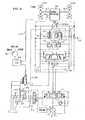
- FIG. 2 shows the travel motion hydraulic circuit in the hydraulically driven vehicle achieved in the first embodiment of the present invention.
- This hydraulic circuit includes a hydraulic pump 10 that is driven by the engine, a travel motion control valve 11 that is operated through a pilot hydraulic circuit 20 to be detailed later and controls the flow rate and the flow direction of the oil output from the hydraulic pump 10, a travel motion variable displacement hydraulic motor 12 (corresponds to 85 in FIG.
- the regulator 14 includes a piston 141 and a servo valve 142.
- a rod chamber 141a at the piston 141 is connected via a pipeline L11 with a shuttle valve 18 used to select the high pressure oil either in the main pipeline L1A or in the main pipeline L1B.
- a bottom chamber 141b at the piston 141 is connected to the servo valve 142 via a pipeline L12.
- the servo valve 142 is switched with a pilot pressure from the pipeline L11 or from a pipeline L20.
- the bottom chamber 141b comes into communication with a drain circuit of the hydraulic motor 12 via a pipeline LD, whereas as the servo valve 142 is switched to a P1 position, the bottom chamber 141b comes into communication with the shuttle valve 18 via the pipeline L11.
- the structural features characterizing the travel motion control apparatus in the embodiment include a rotation rate sensor 95 that is mounted at the transmission 86 and detects the rotation rate of the hydraulic motor 12, a detection line L90 through which a signal output from the rotation rate sensor 95 is extracted, a controller 32 that executes the processing to be detailed later based upon the signal provided through the detection line L90 and an electromagnetic proportional valve 17 that is driven in response to a signal provided by the controller 32.
- the controller 32 is constituted with a CPU, a RAM, an input/output interface and the like.
- the pilot hydraulic circuit 20 includes a pilot hydraulic pump 21, a travel motion pilot valve 22 operated through an accelerator pedal 22a and a forward/reverse switching valve 23 which is switched to a forward position, a reverse position or a neutral position in response to an operation of a forward/reverse change-over switch (not shown).
- the switching direction and the stroke quantity of the control valve 11 are controlled with the pilot pressure supplied from the pilot hydraulic circuit 20.
- the direction and the flow rate of the pressure oil output from the hydraulic pump 10 are controlled through the control valve 11, and the controlled pressure oil is supplied to the hydraulic motor 12 through the counterbalance valve 13.
- the pressure oil supplied to the hydraulic motor 12 causes the hydraulic motor 12 to rotate.
- the rotation of the hydraulic motor 12 is first communicated to the transmission 86 where the rotation speed is reduced at a predetermined gear ratio, and then is communicated to the tires 88F and 88R via the drive shaft 87.
- the hydraulic excavator is thus caused to travel.
- the forward/reverse switching valve 23 assumes the neutral (N) position and the pilot valve 22 is not in an operated state. Under these circumstances, no pilot pressure is applied to the control valve 11 and the control valve 11 is at the neutral position. Thus, the pressure oil from the hydraulic pump 10 is not supplied to the hydraulic motor 12 and the vehicle is in a stopped state.
- the hydraulic circuit in FIG. 2 engages in operation as described below.
- the forward/reverse switching valve 23 As the forward/reverse switching valve 23 is switched to the forward (F) position or the reverse (R) position and the accelerator pedal 22a is depressed, the pilot pressure oil output from the pilot valve 22 travels to a pilot port at the control valve 11, which is switched to the F position or the R position with a stroke quantity corresponding to the pilot pressure. In response, the hydraulic motor 12 is driven and the vehicle engages in travel motion.
- a travel pressure the level of which corresponds to the load, is generated in the pipeline L1A or L1B disposed between the control valve 11 and the counterbalance valve 13.
- This pressure is guided as a torque control pressure to the regulator 14 from the shuttle valve 18 via the pipeline L11.
- the servo valve 142 is switched to the P1 position.
- the rod chamber 141a and the bottom chamber 141b at the piston 141 come into communication with each other and the torque control pressure is guided into both chambers. Since the pressure receiving area in the bottom chamber 141b is greater than the pressure receiving area in the rod chamber 141a, causing the piston to extend, thereby increasing the displacement volume q of the hydraulic motor 12, under these circumstances.
- the servo valve 142 is switched to the maximum position on the P1 side to allow the hydraulic motor 12 to achieve a maximum displacement volume qmax.
- the torque control pressure applied to the regulator 14 becomes lowered, and the servo valve 142 is switched to the P2 position side with the force applied by a spring 142c.
- This change-over in the position of the servo valve causes the bottom chamber 141b to communicate with the drain circuit via the pipeline LD, thereby causing the piston to retract.
- the displacement volume q of the hydraulic motor 12 becomes smaller.
- the operation described above is executed while the vehicle travels on a flat surface, for instance. While the vehicle travels on a flat surface, the rotation rate of the hydraulic motor 12 is kept to a level equal to or less than a rotation rate limit NLim which is a tolerable rotation rate value and the electromagnetic proportional valve 17 is switched to the P2 position as explained later.
- the pilot pressure inside the pipeline L20 is equal to the tank pressure
- the torque control pressure from the shuttle valve 18 alone is applied to the regulator 14, and the displacement volume q of the hydraulic motor 12 is controlled so as not to deviate from a range between the minimum volume qmin and the maximum volume qmax, in correspondence to the level of the traveling pressure.
- FIG. 3 presents a flowchart of an example of the processing executed in the controller 32 in the first embodiment.
- a decision is made by checking a flag in step S1 as to whether or not the motor displacement volume control is currently implemented. If the flag is set to 0, it is judged that the motor displacement volume control is not in progress and the operation proceeds to step S2 to make a decision as to whether or not the motor rotation rate N detected by the rotation rate sensor 95 is equal to or higher than a maximum rotation rate Nmax set in advance.
- the operation proceeds to step S3 if it is decided in step S2 that N ⁇ Nmax, whereas the operation proceeds to step S7 if it is decided that N ⁇ Nmax.
- the flag is set to 1 to start the motor displacement volume control.
- step S4 the operation proceeds to step S4 to make a decision as to whether or not the voltage V output to the electromagnetic proportional valve 17 is equal to a maximum output voltage Vmax.
- the operation proceeds to step S5 if a negative decision is made in step S4, whereas the operation skips step S5 and returns to the start if an affirmative decision is made in step S4.
- step S5 the output voltage V to the electromagnetic proportional valve 17 is increased by a slight quantity ⁇ V. ⁇ V, which is a time function, is set so as to decrease gradually as time passes.
- ⁇ V which is a time function
- step S1 If, on the other hand, it is decided in step S1 that the flag is set to 1, i.e., if it is decided that the motor displacement volume control is currently in effect, the operation proceeds to step S6 to make a decision as to whether or not the motor rotation rate N detected by the rotation rate sensor 95 is equal to or less than a predetermined minimum rotation rate Nmin.
- step S7 the voltage V output to the electromagnetic proportional valve 17 is reduced to 0 and then the flag is set to 0 in the following step S8 to halt the motor displacement volume control.
- the motor rotates at the rotation rate N equaled or less than the maximum rotation rate Nmax when the vehicle travels on a flat surface under normal circumstances.
- the electromagnetic proportional valve 17 is switched to the P2 position through the processing (step S7) described earlier to control the displacement volume q of the hydraulic motor 12 with the travel pressure alone.
- the motor displacement volume control according to the present invention is not implemented to prevent motor over rotation in this situation.
- the motor displacement volume q becomes equal to, for instance, the minimum volume qmin and thus, the motor rotation rate N increases. Then, as the motor rotation rate N becomes equal to the maximum rotation rate Nmax, the motor displacement volume control for over rotation prevention starts and the voltage V output to the electromagnetic proportional valve 17 is gradually increased from the minimum volume qmin through the processing explained earlier (step S5).
- the pressure (the torque control pressure) in the pipeline L20 increases, thereby switching the servo valve 142 to the P1 position, and the motor displacement volume q gradually increases, as shown in FIG. 4(b) .
- the pressure inside the pipeline L20 reaches the maximum level as well and the displacement volume q increases up to a predetermined value qa. This causes an increase in the hydraulic braking force at the hydraulic motor 12 and the over rotation of the hydraulic motor 12 is thus prevented.
- the predetermined value qa is determined in conformance to the maximum pressure level in the pipeline L20, the maximum pressure inside the pipeline L20 is adjusted so as to ensure that the predetermined value qa is smaller than the value of the maximum volume qmax and preferably the predetermined value qa is 40% to 70% of the maximum volume value qmax.
- step S7 the voltage V output to the electromagnetic proportional valve 17 is set to 0 through the processing (step S7) explained earlier.
- the pressure inside the pipeline L20 becomes equal to the tank pressure
- the increase in the motor displacement volume q achieved by using the pressure oil inside the pipeline L20 stops and the motor displacement volume control is halted.
- the displacement volume q of the hydraulic motor 12 is controlled in correspondence to the traveling pressure. As a result, it becomes possible to run the vehicle at an appropriate speed by reducing the hydraulic braking force at the hydraulic motor 12.
- the motor rotation rate N becomes equal to the maximum rotation rate Nmax, the same operation is repeatedly executed.
- FIG. 5 is a diagram of the motor rotation rate N, the motor displacement volume q and the hydraulic braking force at the hydraulic motor 12, measured while the vehicle travels downhill. It is to be noted that the characteristics achieved by implementing the motor displacement volume control are indicated by solid lines and the characteristics manifesting when the motor displacement volume control is not implemented are indicated by dotted lines in the figure.
- the motor displacement volume control is started as the motor rotation rate N reaches the maximum rotation rate level Nmax at a time point t1, and the motor displacement volume q increases until the volume becomes equal to the predetermined value qa as indicated by the solid line in the figure. In response, the motor rotation rate N is decreased, the braking force increases and the vehicle speed is lowered.
- the motor rotation rate N is decreased to a level equal to the minimum rotation rate Nmin at a time point t2, the motor displacement volume control stops and the motor displacement volume q is decreased. As a result, the motor rotation rate N increases to ensure that abrupt braking is not applied to the vehicle.
- the motor displacement volume control when the motor displacement volume control is not implemented, the motor displacement volume q does not increase even if the motor rotation rate N reaches the level equal to the maximum rotation rate Nmax, as indicated by the dotted line in the figure.
- the risk of the motor rotation rate N becoming higher than the maximum rotation rate Nmax as well as the risk of failure to achieve the necessary braking force to result in an increase in the traveling speed arises.
- the motor displacement volume control is implemented so as to increase the motor displacement volume q when the rotation rate N of the hydraulic motor 12 is equal to or greater than the maximum rotation rate Nmax in the first embodiment.
- the braking force applied to the hydraulic motor 12 increases to prevent over rotation of the motor 12, regardless of the specific position assumed by the control valve 11. Since the motor displacement volume control for over rotation prevention is halted once the motor rotation rate N is reduced to a level equal to or lower than the minimum rotation rate Nmin, the vehicle is not allowed to slow down to an excessive extent.
- the motor displacement volume q is gradually increased from the minimum volume qmin to a volume equal to the predetermined value qa which is smaller than the maximum volume qmax through the motor displacement volume control, the extent of the shock occurring as the displacement volume q changes is minimized.
- the hydraulic brake is engaged by increasing the motor displacement volume q through the motor displacement volume control, it is not necessary to add a special braking device and thus, the travel motion control apparatus can be achieved at low cost.
- FIG. 6 is a circuit diagram of the travel motion hydraulic circuit in the hydraulically driven vehicle achieved in the second embodiment. It is to be noted that the same reference numerals are assigned to components identical to those in FIG. 2 and the following explanation focuses on the differences from FIG. 2 .
- the relief valves 15 and 16 are variable relief valves and their relief pressures P15 and P16 change in correspondence to the hydraulic forces applied to oil chambers 15a and 16a respectively.
- the oil chambers 15a and 16a are each connected to an electromagnetic switching valve 17 via the pipeline L20, and the pressures inside the oil chambers 15a and 16a, i.e., the relief pressures P15 and P16, are controlled by switching the electromagnetic switching valve 17.
- the relief pressures P15 and P16 increase in response to the switchover, whereas if the electromagnetic switching valve 17 is switched to the P2 position, the relief pressures P15 and P16 are lowered to the level of a minimum relief pressure Pmin.
- the relief pressures P15 and P16 regulate the hydraulic braking force at the motor 12, and if the relief pressures P15 and P16 are low, the hydraulic braking force, too, is low.
- the minimum relief pressure Pmin is set to a value which is greater than, at least, the relief pressure at a relief valve 19 disposed on the downstream side of the hydraulic pump 10.
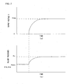
- the processing executed by the controller 32 is basically similar to that shown in FIG. 3 . Namely, as the motor rotation rate N becomes equal to or greater than the maximum rotation rate Nmax, the voltage V output from the controller 32 gradually increases to the level of the maximum output voltage Vmax, as shown in FIG. 7 (a) (step S4, step S5). In response, the relief pressures P15 and P16 gradually increased from the level of the minimum relief pressure Pmin to the level equal to a predetermined value Pa, as shown in FIG. 7(b) .
- the predetermined value Pa is set to a value greater than the minimum relief pressure Pmin by 10 to 30%, by taking into consideration the pressure withstanding performance and the like of the hydraulic parts.
- FIG. 8 shows an example of the operating characteristics manifesting while the vehicle travels downhill.
- the solid lines indicate the characteristics manifesting when the relief pressure control is implemented, whereas the dotted lines indicate the characteristics manifesting when the relief pressure control is not implemented.
- the electromagnetic switching valve 17 is switched toward the P1 position and the relief pressures P15 and P16 increase as indicated by the solid line in the figure.
- the vehicle While traveling downhill, the vehicle is accelerated by gravity and the pressure in the output-side pipeline L1A or L1B increases due to the pumping function of the motor 12.
- the pressure inside the pipeline L1A or L1B is controlled with relief valves 15 and 16, and the higher the relief pressures P15 and P16, the greater the output-side pressure at the motor 12, i.e., the force resisting the rotation of the motor increases as the relief pressures P15 and P16 become higher.
- the hydraulic braking force increases as indicated by the solid line in the figure, slowing down the vehicle.
- the motor rotation rate N becomes lowered to the minimum rotation rate Nmin at a time point t2
- the relief pressures P15 and P16 are reduced to the level of the minimum relief pressure Pmin, thereby decreasing the hydraulic braking force.
- an excessively large braking force is not applied to the vehicle when traveling at low speed to cause it to stop abruptly.
- the hydraulic motor 12 used in the second embodiment does not need to be a variable displacement type motor and instead, it may be a fixed displacement motor.
- the wheel hydraulic excavator shown in FIG. 1 can be mounted with various types of front attachments 84 depending upon the types of work it needs to perform. As the vehicle weight changes when a different attachment 84 is mounted, the inertial force of the vehicle traveling downhill also changes, altering the factor affecting the motor over rotation.
- the third embodiment is achieved by taking into consideration this point.
- the extent to which the motor displacement volume q increases is adjusted in correspondence to the type of front attachment 84 mounted on the vehicle in the third embodiment.
- FIG. 9 is a circuit diagram of the travel motion hydraulic circuit achieved in the third embodiment. It is to be noted that the same reference numerals are assigned to components identical to those in FIG. 2 and the following explanation focuses on the differences from FIG. 2 .
- a dial 33 for attachment selection is connected to the controller 32.
- the dial 33 is switched in correspondence to the specific type of front attachment 84 (e.g., a crusher or a bucket). To facilitate the explanation, it is assumed that the dial is switched to one of three stages, i.e., small, medium and large, in correspondence to the weight of the front attachment 84 mounted on the vehicle.
- the controller 32 executes the following processing based upon signals provided from the dial 33 and the rotation rate sensor 95.
- FIG. 10 presents a flowchart of an example of the processing executed in the controller 32 in the third embodiment. It is to be noted that the same step numbers are assigned to steps in which processing identical to that in FIG. 3 is executed and the following explanation focuses on the differences.
- step S2 After judging in step S2 that the motor rotation rate N is equal to or higher than the maximum rotation rate Nmax and setting the flag to 1 in step S3, the operation proceeds to step S10 to make a decision on the position to which the dial 33 is currently set. If it is decided that the dial is set at "small", i.e., if it is decided that the attachment weight is small, the operation proceeds to step S11.
- step S12 If it is decided that the dial is set at "medium”, i.e., if it is decided that the attachment weight is medium, the operation proceeds to step S12. If it is decided that the dial is set at "large”, i.e., if it is decided that the attachment weight is large, the operation proceeds to step S13.
- steps S11 to S13 a decision is made as to whether or not the voltage V output to the electromagnetic proportional valve 17 is equal to one of predetermined output voltages V1max to V3max. It is to be noted that these predetermined output voltage values are set so as to achieve a relationship express as V1max ⁇ V2max ⁇ V3max. If an affirmative decision is made in steps S11 to S13, the operation returns to the start point. If a negative decision is made in step S11, the operation proceeds to step S14 to increase the voltage output to the electromagnetic proportional valve 17 by a slight extent ⁇ V1. If a negative decision is made in step S12, the operation proceeds to step S15 to increase the output voltage by a slight extent ⁇ V2.
- step S13 If a negative decision is made in step S13, the operation proceeds to step S16 to increase the output by a slight extent ⁇ V3.
- ⁇ V1 to ⁇ V3 are each a time function which is set so as to gradually decrease as time passes, and they are set so as to satisfy ⁇ V1 ⁇ ⁇ V2 ⁇ ⁇ V3.
- the output voltage V gradually increases and the output voltage V reaches the level corresponding to the predetermined value V1max, V2max or V3max when a predetermined length of time ⁇ t elapses following the motor displacement volume control start, as shown in FIG. 11(a) .
- the motor displacement volume q gradually increases so that the motor displacement volume q becomes equal to a predetermined value qa1, qa2 or qa3 when the predetermined length of time ⁇ t elapses following the motor displacement volume control start, as shown in FIG. 11 (b) .
- the operator first switches the dial 33 in correspondence to the specific type of front attachment 84 mounted on the vehicle. For instance, he switches the dial to the "small” position if the vehicle has been mounted with a lightweight front attachment 84, whereas he switches the dial to the "large” position if the vehicle has been mounted with a heavy front attachment 84. If the vehicle travels downhill while the dial is set at "small” or “large” and the motor rotation rate N reaches a level equal to or higher than the maximum rotation rate Nmax, the motor displacement volume q gradually increases through the processing explained earlier (steps S11 and S14 or steps S13 and S16) to become equal to the predetermined value V1max or V3max after the predetermined length of time ⁇ t. Thus, the braking force applied to the hydraulic motor 12 is increased to prevent motor over rotation.
- the displacement volume q is made to increase by a greater extent as the vehicle weight becomes greater (qa3 > qa1) in this situation, a desirable level of braking force corresponding to the inertial force can be imparted. Namely, the braking force is lowered if the inertial force is small so as to ensure that the operator does not experience discomfort due to excessive braking. In addition, if the inertial force is significant, the braking force is increased so as to prevent over rotation of the hydraulic motor 12 with a high degree of reliability.
- the braking force is made to increase to a greater extent as the inertial force becomes larger and, as a result, over rotation of the motor 12 can be reliably prevented without imparting and excessive braking force.
- the motor displacement volume q is made to increase by a greater extent as the weight of the front attachment 84 becomes larger, the motor displacement volume q stops increasing when the predetermined length of time ⁇ t elapses following the motor displacement volume control start.
- the voltage V output from the controller 32 may manifest characteristics different from those shown in FIG. 11(a) .
- the output voltage V may manifest characteristics so that the output voltage V becomes equal to the predetermined value V1max, V2max or V3max sooner as the weight of the front attachment 84 becomes greater, i.e., ⁇ t1 > ⁇ t2 > ⁇ t3, as shown in FIG. 12(a) , instead of becoming equal to the predetermined value V1max, V2max or V3max after the predetermined length of time ⁇ t.
- the increase rate of the output voltage V alone may be adjusted so as to allow the output voltage V to increase up to a predetermined level Vmax, as shown in FIG. 12(b) .
- the patterns with which the output voltage V may increase are not limited to those described above, and the output voltage V may instead be made to increase in steps, for instance.
- the motor rotation rate Nmax detected at the motor displacement volume control start in step S2 and the motor rotation rate Nmin detected at the motor displacement volume control end in step S6 may be adjusted in correspondence to the level of the inertial force of the vehicle.
- the characteristics of the output voltage V may be adjusted based upon the mounting state of another component (e.g., an outrigger (a stabilizer) or a blade) that affects the inertial force of the vehicle.
- the characteristics may be adjusted based upon the state of inclination of the vehicle.
- a tilt sensor for instance, may be installed in the vehicle to detect the angle of inclination of the vehicle so as to enable the controller 32 to select the characteristics whereby the output voltage V increases to a greater degree as the downhill slope becomes steeper.
- the downhill grade of the road may be ascertained from road information or the like provided by a navigation apparatus and the characteristics of the output voltage V to be achieved while the vehicle travels downhill may be adjusted based upon the downhill grade.
- feedback control of the motor rotation N is executed so as to set the motor rotation rate N to a target rotation rate Na in the event of a motor over rotation.
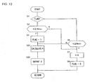
- FIG. 13 presents a flowchart of an example of the processing executed in the controller 32 in the fourth embodiment. It is to be noted that the same step numbers are assigned to steps in which processing identical to that in FIG. 3 is executed and the following explanation focuses on the differences.
- step S2 After judging in step S2 that the motor rotation rate N is equal to or higher than the maximum rotation rate Nmax and setting the flag to 1 in step S3, the operation proceeds to step S21.
- step S21 a target displacement volume qA corresponding to a deviation ⁇ N of the motor rotation rate N relative to the target rotation rate Nmax is calculated as detailed later.
- an output voltage V corresponding to the target displacement volume qA is output to the electromagnetic proportional valve 17 in step S22.
- the motor displacement volume q becomes equal to the target displacement volume qA, thereby equalizing the motor rotation rate N with the target rotation rate Na through the control.
- FIG. 14 is a block diagram of the details of the processing executed in step S21.
- a subtractor 51 subtracts the target rotation rate Na determined in advance for the motor 12 from the motor rotation rate N detected by the rotation rate sensor 95 and thus ascertains a motor rotation rate difference ⁇ N.
- the target rotation rate Na may be set equal to, for instance, the maximum rotation rate Nmax.
- the motor displacement volume q is controlled in correspondence to the deviation ⁇ N of the motor rotation rate N relative to the target rotation rate Na, it is possible to implement accurate control on the motor rotation rate N to set it equal to the target rotation rate Na.
- the function generator 52 ensures that the motor displacement volume q is increased by a greater extent as the motor rotation rate difference ⁇ N becomes larger, the motor rotation rate N reaches a level close to the target rotation rate Na quickly.
- the present invention which is characterized in that the brakes are engaged when an over rotation of the travel motion motor 12 occurs, may be realized in any of various modes other than those adopted in the embodiments explained above.
- the hydraulic breaking force is increased by increasing the motor displacement volume q or increasing the relief pressures P15 and P16 at the relief valves 15 and 16 in the embodiments described above, a means for motor over rotation prevention other than these may be adopted.
- the breaking force may be increased as the service break is engaged or as the transmission 86 is forcibly switched to the low gear position. If there are at least three speed levels at the transmission, the gears may be shifted from a high gear to a medium gear and from the medium gear to a low gear.
- the means for operation may be constituted by using a member other than the pedal member.
- the rotation rate sensor 95 is used as the means for rotation rate detection so as to directly detect the motor rotation rate N
- the motor rotation rate N may be detected indirectly based upon a physical quantity having a correlation with the motor rotation rate N.
- the motor rotation rate N may be indirectly detected in correspondence to the gear ratio at the transmission 86 and the vehicle speed.
- the means for motor displacement volume control such as the regulator 14 does not need to be provided if the breaking force is increased through control other than motor displacement volume control.
- the displacement volume q may also be changed gradually when the motor displacement volume q is decreased (the time point t2 in FIG. 5 ) as well as when the motor displacement volume q is increased (the time point t1 in FIG. 5 ).
- the pressure in the pipeline L20 may be gradually increased with a restrictor formed at the pipeline L20 as well so that the electromagnetic proportional valve 17 can be switched to on or off.
- the present invention may also be adopted in other types of work vehicles that are driven with a hydraulic motor 12, including wheel loaders and truck cranes.
- the present invention may be realized by using a so-called HST (hydrostatic transmission) hydraulic circuit achieved through a closed circuit connection of a hydraulic pump and a hydraulic motor, as long as the displacement volume control on the hydraulic motor is achieved based upon the drive pressure.
- HST hydrostatic transmission
Landscapes
- Engineering & Computer Science (AREA)
- General Engineering & Computer Science (AREA)
- Mechanical Engineering (AREA)
- Operation Control Of Excavators (AREA)
- Control Of Fluid Gearings (AREA)
- Motor Power Transmission Devices (AREA)
- Fluid-Pressure Circuits (AREA)
Claims (6)
- Fortbewegungssteuerungsvorrichtung für ein hydraulisch angetriebenes Fahrzeug, umfassend:eine Hydraulikpumpe (10), die von einem Antriebsmotor angetrieben wird;einen Fortbewegungsmotor (12), der mit Hydrauliköl angetrieben wird, das von der Hydraulikpumpe (10) geliefert wird;ein Mittel zur Motorfördervolumensteuerung (14), die ein Fördervolumen des Fortbewegungsmotors (12) so steuert, dass das Fördervolumen abnimmt, wenn ein Fortbewegungsdruck des Fortbewegungsmotors (12) abnimmt, und das Fördervolumen zunimmt, wenn der Fortbewegungsdruck des Fortbewegungsmotors (12) zunimmt;ein Fortbewegungsmotor-Steuerventil (11), das eine Strömungsrate des von der Hydraulikpumpe (10) an den Fortbewegungsmotor (12) gelieferten Hydrauliköls steuert;ein Mittel zur Betätigung (20), mit dem das Fortbewegungs-Steuerventil (11) betätigt wird, um in einer von dem Fortbewegungs-Steuerventil (11) zum Fortbewegungsmotor (12) führenden Leitung (L1A, L1B) durch das von der Hydraulikpumpe (10) geförderte Hydrauliköl den Fortbewegungsdruck zu erzeugen, wobei der Fortbewegungsdruck je nach einer Last variiert und abnimmt, wenn sich das Fahrzeug bergab fortbewegt;ein Mittel zur Drehzahlerfassung (95, 32), das eine Drehzahl des Fortbewegungsmotors (12) erfasst; und gekennzeichnet durchein Mittel zum Motorüberdrehschutz (32, 17), das das Fördervolumen des Fortbewegungsmotors (12) auf ein Niveau erhöht, das gleich einem vorbestimmten Wert ist, der kleiner als ein maximales Fördervolumen ist, wenn das Mittel zur Drehzahlerfassung (95, 32) eine Drehzahl erfasst, die größer oder gleich einem vorbestimmten oberen Drehzahlgrenzwert ist, der kleiner oder gleich einem zugelassenen Drehzahlgrenzwert des Fortbewegungsmotors (12) ist, und zwar unabhängig von einer Steuerung des Mittels zur Motorfördervolumensteuerung (14), das in Reaktion darauf, dass der gemäß einer Betätigung des Mittels zur Betätigung (20) erzeugte Fortbewegungsdruck abnimmt, wenn sich das Fahrzeug bergab fortbewegt, eine Steuerung ausführt, um ein Fördervolumen des Fortbewegungsmotors (12) zu verringern, wobei:das Mittel zum Motorüberdrehschutz (32, 17) eine Steuerung zum Erhöhen des Fördervolumens des Fortbewegungsmotors (12) stoppt, nachdem die Drehzahl des Fortbewegungsmotors (12) kleiner oder gleich einem vorbestimmten unteren Drehzahlgrenzwert geworden ist, der mindestens kleiner als der obere Drehzahlgrenzwert ist, und das Fördervolumen des Fortbewegungsmotors (12) von dem Mittel zur Motorfördervolumensteuerung (14) in Entsprechung zu dem Fortbewegungsdruck gesteuert wird.
- Fortbewegungssteuerungsvorrichtung für ein hydraulisch angetriebenes Fahrzeug nach Anspruch 1, ferner umfassend:ein Ausgleichsventil (13), das zwischen dem Fortbewegungsmotor (12) und dem Fortbewegungs-Steuerventil (11) angeordnet ist, das von einem von der Hydraulikpumpe (10) ausgegebenen Fortbewegungsdruck gesteuert wird.
- Fortbewegungssteuerungsvorrichtung für ein hydraulisch angetriebenes Fahrzeug nach einem der Ansprüche 1 bis 2, wobei:wenn das Mittel zur Drehzahlerfassung (95, 32) eine Drehzahl erfasst, die größer oder gleich dem oberen Drehzahlgrenzwert ist, das Mittel zum Motorüberdrehschutz (32, 17) allmählich die Förderleistung des Fortbewegungsmotors (12) erhöht.
- Fortbewegungssteuerungsvorrichtung für ein hydraulisch angetriebenes Fahrzeug nach einem der Ansprüche 1 bis 3, wobei:das Mittel zum Motorüberdrehschutz (32, 17) das Fördervolumen des Fortbewegungsmotors (12) so erhöht, dass das Fördervolumen des Fortbewegungsmotors (12) schließlich 40% - 70% eines maximalen Fördervolumens des Fortbewegungsmotors (12) beträgt.
- Hydraulisch angetriebenes Fahrzeug, umfassend eine Fortbewegungssteuerungsvorrichtung nach einem der Ansprüche 1 bis 4.
- Hydraulischer Radbagger, umfassend eine Fortbewegungssteuerungsvorrichtung nach einem der Ansprüche 1 bis 4.
Applications Claiming Priority (3)
| Application Number | Priority Date | Filing Date | Title |
|---|---|---|---|
| JP2002126313 | 2002-04-26 | ||
| JP2002126313 | 2002-04-26 | ||
| PCT/JP2003/004634 WO2003091606A1 (en) | 2002-04-26 | 2003-04-11 | Travel control device of hydraulically driven vehicle, hydraulically driven vehicle, and wheel hydraulic shovel |
Publications (3)
| Publication Number | Publication Date |
|---|---|
| EP1500850A1 EP1500850A1 (de) | 2005-01-26 |
| EP1500850A4 EP1500850A4 (de) | 2008-08-13 |
| EP1500850B1 true EP1500850B1 (de) | 2011-06-08 |
Family
ID=29267595
Family Applications (1)
| Application Number | Title | Priority Date | Filing Date |
|---|---|---|---|
| EP20030717566 Expired - Lifetime EP1500850B1 (de) | 2002-04-26 | 2003-04-11 | Fahrsteuervorrichtung für hydraulisch angetriebenes fahrzeug, hydraulisch angetriebenes fahrzeug und hydraulischer bagger auf rädern |
Country Status (6)
| Country | Link |
|---|---|
| US (2) | US20050161090A1 (de) |
| EP (1) | EP1500850B1 (de) |
| JP (1) | JP4216200B2 (de) |
| CN (1) | CN100383434C (de) |
| AT (1) | ATE512327T1 (de) |
| WO (1) | WO2003091606A1 (de) |
Families Citing this family (22)
| Publication number | Priority date | Publication date | Assignee | Title |
|---|---|---|---|---|
| JP5247025B2 (ja) * | 2006-12-28 | 2013-07-24 | 日立建機株式会社 | 油圧式走行車両の走行制御装置 |
| JP5135169B2 (ja) * | 2008-10-31 | 2013-01-30 | 日立建機株式会社 | 建設機械の油圧駆動装置 |
| JP5301509B2 (ja) * | 2010-08-31 | 2013-09-25 | 日立建機株式会社 | 作業車両の走行制御装置 |
| CN102052363B (zh) * | 2010-12-29 | 2013-06-19 | 北京市三一重机有限公司 | 可控低速大扭矩动力头马达 |
| JP5333511B2 (ja) * | 2011-05-02 | 2013-11-06 | コベルコ建機株式会社 | 旋回式作業機械 |
| JP5738674B2 (ja) | 2011-05-25 | 2015-06-24 | コベルコ建機株式会社 | 旋回式作業機械 |
| FI124159B (fi) * | 2011-06-27 | 2014-04-15 | John Deere Forestry Oy | Työkoneen hydraulisen ajovoimansiirron järjestelmä ja menetelmä |
| US8776511B2 (en) * | 2011-06-28 | 2014-07-15 | Caterpillar Inc. | Energy recovery system having accumulator and variable relief |
| US8919113B2 (en) | 2011-06-28 | 2014-12-30 | Caterpillar Inc. | Hydraulic control system having energy recovery kit |
| KR101908547B1 (ko) * | 2011-08-26 | 2018-12-18 | 볼보 컨스트럭션 이큅먼트 에이비 | 유압구동 작업기계를 작동시키는 시스템 및 구동제어 방법 |
| JP5356476B2 (ja) * | 2011-09-06 | 2013-12-04 | 住友建機株式会社 | 建設機械 |
| US20140100743A1 (en) * | 2012-10-04 | 2014-04-10 | Cnh America Llc | Travel speed control system for work vehicle |
| US20140260224A1 (en) * | 2013-03-14 | 2014-09-18 | Clark Equipment Company | Control System for Variable Displacement Hydraulic Motor |
| US9512918B2 (en) * | 2013-06-14 | 2016-12-06 | Danfoss Power Solutions Inc. | Speed control system for a hydrostatic transmission |
| JP6738782B2 (ja) * | 2017-09-14 | 2020-08-12 | 日立建機株式会社 | 建設機械の駆動装置 |
| JP7156806B2 (ja) * | 2018-02-23 | 2022-10-19 | 株式会社小松製作所 | 作業車両、及び、作業車両の制御方法 |
| JP7033036B2 (ja) * | 2018-08-29 | 2022-03-09 | Kyb株式会社 | 反転防止弁 |
| WO2021055917A1 (en) | 2019-09-19 | 2021-03-25 | Clark Equipment Company | Drive motor displacement control |
| CN111691492B (zh) * | 2020-06-30 | 2022-06-28 | 徐州徐工挖掘机械有限公司 | 挖掘机的液压系统和挖掘机 |
| CA3188396A1 (en) * | 2020-08-04 | 2022-02-10 | John S. Moley | Generator motor flow control valve |
| US11198988B1 (en) * | 2020-12-23 | 2021-12-14 | Cnh Industrial America Llc | Speed-limiting calibration control for a hydraulic system |
| CN116176635A (zh) * | 2023-03-03 | 2023-05-30 | 中铁工程机械研究设计院有限公司 | 一种驱动力自适应液压系统及轨道平板车 |
Family Cites Families (14)
| Publication number | Priority date | Publication date | Assignee | Title |
|---|---|---|---|---|
| FR1123608A (fr) * | 1953-12-19 | 1956-09-25 | Transmission hydraulique, en particulier pour véhicules | |
| DE1931533A1 (de) * | 1969-06-21 | 1971-01-07 | Hako Werke Hans Koch & Sohn | Einrichtung zur Steuerung von hydraulischen Antrieben |
| US3864910A (en) * | 1972-05-24 | 1975-02-11 | Poclain Sa | Device for supplying fluid under pressure to two reversible load elements |
| JPS57107666U (de) * | 1980-12-24 | 1982-07-02 | ||
| JPH01116371A (ja) * | 1987-10-28 | 1989-05-09 | Mitsubishi Heavy Ind Ltd | 雪上車の車両走行速度切換装置 |
| DE4212983C1 (en) * | 1992-04-18 | 1993-05-13 | Man Nutzfahrzeuge Ag, 8000 Muenchen, De | Drive transmission for lorry or bus with all-wheel retarding system - includes hydrostatic machines assigned to front wheels also used for pump and braking action |
| DE4234826C1 (de) * | 1992-10-15 | 1993-10-28 | Hydromatik Gmbh | Hydrostatisches Getriebe |
| JP3266348B2 (ja) * | 1992-12-24 | 2002-03-18 | 日立建機株式会社 | 作業車両の走行用油圧モータ駆動回路 |
| US5435131A (en) * | 1994-04-11 | 1995-07-25 | Caterpillar Inc. | Adaptive overspeed control for a hydrostatic transmission |
| JP3400178B2 (ja) * | 1995-03-31 | 2003-04-28 | 日立建機株式会社 | 油圧駆動車両の走行制御装置 |
| JP3631620B2 (ja) * | 1998-08-26 | 2005-03-23 | 新キャタピラー三菱株式会社 | 車両の走行速度制御装置 |
| US6321867B1 (en) * | 1998-11-05 | 2001-11-27 | New Holland North America, Inc. | Charge flow supplement circuit for tractors |
| JP3884178B2 (ja) * | 1998-11-27 | 2007-02-21 | 日立建機株式会社 | 旋回制御装置 |
| JP2001304409A (ja) * | 2000-04-21 | 2001-10-31 | Komatsu Ltd | 油圧モータの容量制御装置 |
-
2003
- 2003-04-11 CN CNB038092972A patent/CN100383434C/zh not_active Expired - Lifetime
- 2003-04-11 WO PCT/JP2003/004634 patent/WO2003091606A1/ja not_active Ceased
- 2003-04-11 JP JP2003588111A patent/JP4216200B2/ja not_active Expired - Fee Related
- 2003-04-11 EP EP20030717566 patent/EP1500850B1/de not_active Expired - Lifetime
- 2003-04-11 US US10/512,146 patent/US20050161090A1/en not_active Abandoned
- 2003-04-11 AT AT03717566T patent/ATE512327T1/de not_active IP Right Cessation
-
2007
- 2007-08-13 US US11/889,426 patent/US7698891B2/en not_active Expired - Fee Related
Also Published As
| Publication number | Publication date |
|---|---|
| US20050161090A1 (en) | 2005-07-28 |
| JP4216200B2 (ja) | 2009-01-28 |
| CN1650123A (zh) | 2005-08-03 |
| EP1500850A1 (de) | 2005-01-26 |
| ATE512327T1 (de) | 2011-06-15 |
| US20070289639A1 (en) | 2007-12-20 |
| US7698891B2 (en) | 2010-04-20 |
| CN100383434C (zh) | 2008-04-23 |
| JPWO2003091606A1 (ja) | 2005-09-02 |
| EP1500850A4 (de) | 2008-08-13 |
| WO2003091606A1 (en) | 2003-11-06 |
Similar Documents
| Publication | Publication Date | Title |
|---|---|---|
| US7698891B2 (en) | Travel motion control apparatus for hydraulically driven vehicle, hydraulically driven vehicle and wheel hydraulic excavator | |
| EP1674766B1 (de) | Fahrsteuervorrichtung für hydraulisch angetriebenes fahrzeug und hydraulisch angetriebenes fahrzeug | |
| US7987941B2 (en) | Construction vehicle with controller for suppressing reduction of traction force under low speed traveling condition | |
| JP5072926B2 (ja) | 作業車両 | |
| JP5192601B1 (ja) | 作業車両及び作業車両の制御方法 | |
| JP5092060B1 (ja) | 作業車両及び作業車両の制御方法 | |
| JP5092061B1 (ja) | 作業車両及び作業車両の制御方法 | |
| CN101535687B (zh) | 液压式行驶车辆的行驶控制装置 | |
| KR20040038657A (ko) | 유압구동차량 | |
| JP2011052794A (ja) | 作業車両 | |
| EP3795755B1 (de) | Nutzfahrzeug für frachtumschlag | |
| US7506717B2 (en) | Hydraulically driven vehicle | |
| JP4121687B2 (ja) | 油圧走行車両 | |
| JP3999618B2 (ja) | 油圧駆動車両の走行制御装置および油圧駆動車両 | |
| KR100682565B1 (ko) | 유압 구동 차량의 주행 제어 장치, 유압 구동 차량, 및휠식 유압 셔블 |
Legal Events
| Date | Code | Title | Description |
|---|---|---|---|
| PUAI | Public reference made under article 153(3) epc to a published international application that has entered the european phase |
Free format text: ORIGINAL CODE: 0009012 |
|
| 17P | Request for examination filed |
Effective date: 20041026 |
|
| AK | Designated contracting states |
Kind code of ref document: A1 Designated state(s): AT BE BG CH CY CZ DE DK EE ES FI FR GB GR HU IE IT LI LU MC NL PT RO SE SI SK TR |
|
| A4 | Supplementary search report drawn up and despatched |
Effective date: 20080714 |
|
| RIC1 | Information provided on ipc code assigned before grant |
Ipc: F16H 61/42 20060101AFI20031113BHEP Ipc: F16H 61/40 20060101ALI20080708BHEP Ipc: F16H 61/46 20060101ALI20080708BHEP |
|
| 17Q | First examination report despatched |
Effective date: 20090615 |
|
| RIC1 | Information provided on ipc code assigned before grant |
Ipc: F16H 61/4157 20100101ALI20101007BHEP Ipc: F16H 61/421 20100101ALI20101007BHEP Ipc: F16H 61/47 20100101ALI20101007BHEP Ipc: F16H 61/4017 20100101AFI20101007BHEP |
|
| GRAP | Despatch of communication of intention to grant a patent |
Free format text: ORIGINAL CODE: EPIDOSNIGR1 |
|
| GRAS | Grant fee paid |
Free format text: ORIGINAL CODE: EPIDOSNIGR3 |
|
| GRAA | (expected) grant |
Free format text: ORIGINAL CODE: 0009210 |
|
| AK | Designated contracting states |
Kind code of ref document: B1 Designated state(s): AT BE BG CH CY CZ DE DK EE ES FI FR GB GR HU IE IT LI LU MC NL PT RO SE SI SK TR |
|
| REG | Reference to a national code |
Ref country code: GB Ref legal event code: FG4D |
|
| REG | Reference to a national code |
Ref country code: CH Ref legal event code: EP |
|
| REG | Reference to a national code |
Ref country code: IE Ref legal event code: FG4D |
|
| REG | Reference to a national code |
Ref country code: DE Ref legal event code: R096 Ref document number: 60337331 Country of ref document: DE Effective date: 20110721 |
|
| REG | Reference to a national code |
Ref country code: NL Ref legal event code: VDEP Effective date: 20110608 |
|
| PG25 | Lapsed in a contracting state [announced via postgrant information from national office to epo] |
Ref country code: SE Free format text: LAPSE BECAUSE OF FAILURE TO SUBMIT A TRANSLATION OF THE DESCRIPTION OR TO PAY THE FEE WITHIN THE PRESCRIBED TIME-LIMIT Effective date: 20110608 |
|
| PG25 | Lapsed in a contracting state [announced via postgrant information from national office to epo] |
Ref country code: ES Free format text: LAPSE BECAUSE OF FAILURE TO SUBMIT A TRANSLATION OF THE DESCRIPTION OR TO PAY THE FEE WITHIN THE PRESCRIBED TIME-LIMIT Effective date: 20110919 Ref country code: FI Free format text: LAPSE BECAUSE OF FAILURE TO SUBMIT A TRANSLATION OF THE DESCRIPTION OR TO PAY THE FEE WITHIN THE PRESCRIBED TIME-LIMIT Effective date: 20110608 Ref country code: SI Free format text: LAPSE BECAUSE OF FAILURE TO SUBMIT A TRANSLATION OF THE DESCRIPTION OR TO PAY THE FEE WITHIN THE PRESCRIBED TIME-LIMIT Effective date: 20110608 Ref country code: GR Free format text: LAPSE BECAUSE OF FAILURE TO SUBMIT A TRANSLATION OF THE DESCRIPTION OR TO PAY THE FEE WITHIN THE PRESCRIBED TIME-LIMIT Effective date: 20110909 Ref country code: AT Free format text: LAPSE BECAUSE OF FAILURE TO SUBMIT A TRANSLATION OF THE DESCRIPTION OR TO PAY THE FEE WITHIN THE PRESCRIBED TIME-LIMIT Effective date: 20110608 Ref country code: CY Free format text: LAPSE BECAUSE OF FAILURE TO SUBMIT A TRANSLATION OF THE DESCRIPTION OR TO PAY THE FEE WITHIN THE PRESCRIBED TIME-LIMIT Effective date: 20110608 |
|
| PG25 | Lapsed in a contracting state [announced via postgrant information from national office to epo] |
Ref country code: BE Free format text: LAPSE BECAUSE OF FAILURE TO SUBMIT A TRANSLATION OF THE DESCRIPTION OR TO PAY THE FEE WITHIN THE PRESCRIBED TIME-LIMIT Effective date: 20110608 Ref country code: NL Free format text: LAPSE BECAUSE OF FAILURE TO SUBMIT A TRANSLATION OF THE DESCRIPTION OR TO PAY THE FEE WITHIN THE PRESCRIBED TIME-LIMIT Effective date: 20110608 |
|
| PG25 | Lapsed in a contracting state [announced via postgrant information from national office to epo] |
Ref country code: CZ Free format text: LAPSE BECAUSE OF FAILURE TO SUBMIT A TRANSLATION OF THE DESCRIPTION OR TO PAY THE FEE WITHIN THE PRESCRIBED TIME-LIMIT Effective date: 20110608 Ref country code: EE Free format text: LAPSE BECAUSE OF FAILURE TO SUBMIT A TRANSLATION OF THE DESCRIPTION OR TO PAY THE FEE WITHIN THE PRESCRIBED TIME-LIMIT Effective date: 20110608 Ref country code: PT Free format text: LAPSE BECAUSE OF FAILURE TO SUBMIT A TRANSLATION OF THE DESCRIPTION OR TO PAY THE FEE WITHIN THE PRESCRIBED TIME-LIMIT Effective date: 20111010 |
|
| PG25 | Lapsed in a contracting state [announced via postgrant information from national office to epo] |
Ref country code: RO Free format text: LAPSE BECAUSE OF FAILURE TO SUBMIT A TRANSLATION OF THE DESCRIPTION OR TO PAY THE FEE WITHIN THE PRESCRIBED TIME-LIMIT Effective date: 20110608 Ref country code: SK Free format text: LAPSE BECAUSE OF FAILURE TO SUBMIT A TRANSLATION OF THE DESCRIPTION OR TO PAY THE FEE WITHIN THE PRESCRIBED TIME-LIMIT Effective date: 20110608 |
|
| PLBE | No opposition filed within time limit |
Free format text: ORIGINAL CODE: 0009261 |
|
| STAA | Information on the status of an ep patent application or granted ep patent |
Free format text: STATUS: NO OPPOSITION FILED WITHIN TIME LIMIT |
|
| 26N | No opposition filed |
Effective date: 20120309 |
|
| PG25 | Lapsed in a contracting state [announced via postgrant information from national office to epo] |
Ref country code: DK Free format text: LAPSE BECAUSE OF FAILURE TO SUBMIT A TRANSLATION OF THE DESCRIPTION OR TO PAY THE FEE WITHIN THE PRESCRIBED TIME-LIMIT Effective date: 20110608 |
|
| REG | Reference to a national code |
Ref country code: DE Ref legal event code: R097 Ref document number: 60337331 Country of ref document: DE Effective date: 20120309 |
|
| PG25 | Lapsed in a contracting state [announced via postgrant information from national office to epo] |
Ref country code: MC Free format text: LAPSE BECAUSE OF NON-PAYMENT OF DUE FEES Effective date: 20120430 |
|
| REG | Reference to a national code |
Ref country code: CH Ref legal event code: PL |
|
| REG | Reference to a national code |
Ref country code: IE Ref legal event code: MM4A |
|
| PG25 | Lapsed in a contracting state [announced via postgrant information from national office to epo] |
Ref country code: IE Free format text: LAPSE BECAUSE OF NON-PAYMENT OF DUE FEES Effective date: 20120411 Ref country code: LI Free format text: LAPSE BECAUSE OF NON-PAYMENT OF DUE FEES Effective date: 20120430 Ref country code: CH Free format text: LAPSE BECAUSE OF NON-PAYMENT OF DUE FEES Effective date: 20120430 |
|
| PG25 | Lapsed in a contracting state [announced via postgrant information from national office to epo] |
Ref country code: BG Free format text: LAPSE BECAUSE OF FAILURE TO SUBMIT A TRANSLATION OF THE DESCRIPTION OR TO PAY THE FEE WITHIN THE PRESCRIBED TIME-LIMIT Effective date: 20110908 |
|
| PG25 | Lapsed in a contracting state [announced via postgrant information from national office to epo] |
Ref country code: TR Free format text: LAPSE BECAUSE OF FAILURE TO SUBMIT A TRANSLATION OF THE DESCRIPTION OR TO PAY THE FEE WITHIN THE PRESCRIBED TIME-LIMIT Effective date: 20110608 |
|
| PG25 | Lapsed in a contracting state [announced via postgrant information from national office to epo] |
Ref country code: LU Free format text: LAPSE BECAUSE OF NON-PAYMENT OF DUE FEES Effective date: 20120411 |
|
| PG25 | Lapsed in a contracting state [announced via postgrant information from national office to epo] |
Ref country code: HU Free format text: LAPSE BECAUSE OF FAILURE TO SUBMIT A TRANSLATION OF THE DESCRIPTION OR TO PAY THE FEE WITHIN THE PRESCRIBED TIME-LIMIT Effective date: 20030411 |
|
| REG | Reference to a national code |
Ref country code: FR Ref legal event code: PLFP Year of fee payment: 14 |
|
| REG | Reference to a national code |
Ref country code: FR Ref legal event code: PLFP Year of fee payment: 15 |
|
| REG | Reference to a national code |
Ref country code: FR Ref legal event code: PLFP Year of fee payment: 16 |
|
| PGFP | Annual fee paid to national office [announced via postgrant information from national office to epo] |
Ref country code: GB Payment date: 20180329 Year of fee payment: 16 |
|
| PGFP | Annual fee paid to national office [announced via postgrant information from national office to epo] |
Ref country code: FR Payment date: 20180315 Year of fee payment: 16 |
|
| PGFP | Annual fee paid to national office [announced via postgrant information from national office to epo] |
Ref country code: IT Payment date: 20180420 Year of fee payment: 16 |
|
| GBPC | Gb: european patent ceased through non-payment of renewal fee |
Effective date: 20190411 |
|
| PG25 | Lapsed in a contracting state [announced via postgrant information from national office to epo] |
Ref country code: GB Free format text: LAPSE BECAUSE OF NON-PAYMENT OF DUE FEES Effective date: 20190411 |
|
| PG25 | Lapsed in a contracting state [announced via postgrant information from national office to epo] |
Ref country code: FR Free format text: LAPSE BECAUSE OF NON-PAYMENT OF DUE FEES Effective date: 20190430 |
|
| PG25 | Lapsed in a contracting state [announced via postgrant information from national office to epo] |
Ref country code: IT Free format text: LAPSE BECAUSE OF NON-PAYMENT OF DUE FEES Effective date: 20190411 |
|
| PGFP | Annual fee paid to national office [announced via postgrant information from national office to epo] |
Ref country code: DE Payment date: 20220302 Year of fee payment: 20 |
|
| REG | Reference to a national code |
Ref country code: DE Ref legal event code: R071 Ref document number: 60337331 Country of ref document: DE |