EP1500619B1 - Verfahren und Vorrichtung zum Herstellen einer Garnspule - Google Patents
Verfahren und Vorrichtung zum Herstellen einer Garnspule Download PDFInfo
- Publication number
- EP1500619B1 EP1500619B1 EP20040016735 EP04016735A EP1500619B1 EP 1500619 B1 EP1500619 B1 EP 1500619B1 EP 20040016735 EP20040016735 EP 20040016735 EP 04016735 A EP04016735 A EP 04016735A EP 1500619 B1 EP1500619 B1 EP 1500619B1
- Authority
- EP
- European Patent Office
- Prior art keywords
- package
- yarn
- winding
- rotations
- total
- Prior art date
- Legal status (The legal status is an assumption and is not a legal conclusion. Google has not performed a legal analysis and makes no representation as to the accuracy of the status listed.)
- Expired - Lifetime
Links
- 238000004519 manufacturing process Methods 0.000 title claims description 7
- 238000004804 winding Methods 0.000 claims description 143
- 238000000034 method Methods 0.000 claims description 40
- 238000012937 correction Methods 0.000 description 120
- 238000003860 storage Methods 0.000 description 24
- 230000006870 function Effects 0.000 description 14
- 238000001514 detection method Methods 0.000 description 8
- 238000004891 communication Methods 0.000 description 5
- 238000010586 diagram Methods 0.000 description 5
- 230000007547 defect Effects 0.000 description 3
- 238000010977 unit operation Methods 0.000 description 3
- UUQHAAWMCLITRZ-KEOOTSPTSA-N 2-[(3S,6S,12S,20R,23S)-20-carbamoyl-12-[3-(diaminomethylideneamino)propyl]-3-(1H-indol-3-ylmethyl)-2,5,8,11,14,22-hexaoxo-17,18-dithia-1,4,7,10,13,21-hexazabicyclo[21.3.0]hexacosan-6-yl]acetic acid Chemical compound N1C(=O)[C@H](CC(O)=O)NC(=O)CNC(=O)[C@H](CCCN=C(N)N)NC(=O)CCSSC[C@@H](C(N)=O)NC(=O)[C@@H]2CCCN2C(=O)[C@@H]1CC1=CNC2=CC=CC=C12 UUQHAAWMCLITRZ-KEOOTSPTSA-N 0.000 description 2
- 238000005520 cutting process Methods 0.000 description 1
- 230000007423 decrease Effects 0.000 description 1
- 230000002950 deficient Effects 0.000 description 1
- 230000003111 delayed effect Effects 0.000 description 1
- 239000000284 extract Substances 0.000 description 1
- 230000001939 inductive effect Effects 0.000 description 1
- 238000009987 spinning Methods 0.000 description 1
Images






Classifications
-
- B—PERFORMING OPERATIONS; TRANSPORTING
- B65—CONVEYING; PACKING; STORING; HANDLING THIN OR FILAMENTARY MATERIAL
- B65H—HANDLING THIN OR FILAMENTARY MATERIAL, e.g. SHEETS, WEBS, CABLES
- B65H63/00—Warning or safety devices, e.g. automatic fault detectors, stop-motions ; Quality control of the package
- B65H63/08—Warning or safety devices, e.g. automatic fault detectors, stop-motions ; Quality control of the package responsive to delivery of a measured length of material, completion of winding of a package, or filling of a receptacle
- B65H63/084—Warning or safety devices, e.g. automatic fault detectors, stop-motions ; Quality control of the package responsive to delivery of a measured length of material, completion of winding of a package, or filling of a receptacle responsive to a predetermined weight of the package
-
- B—PERFORMING OPERATIONS; TRANSPORTING
- B65—CONVEYING; PACKING; STORING; HANDLING THIN OR FILAMENTARY MATERIAL
- B65H—HANDLING THIN OR FILAMENTARY MATERIAL, e.g. SHEETS, WEBS, CABLES
- B65H2701/00—Handled material; Storage means
- B65H2701/30—Handled filamentary material
- B65H2701/31—Textiles threads or artificial strands of filaments
Definitions
- the present invention relates to a method of manufacturing a package in an automatic winder and a yarn winder according to the preamble of claim 1 and 3, respectively..
- An automatic winder as disclosed in the Unexamined Japanese Utility Model Application Publication No. 5-5768 comprises a plurality of winding units each of which splices a large number of yarns together which are wound around yarn supplying bobbins, while eliminating defects in the yarns, to rewind the spliced yarns around a cone-like winding bobbin.
- each winding unit when the yarn is rewound around the winding bobbin, the length of the yarn is measured. Then, once a package with a predetermined length of yarn is obtained, this package is cut off. Then, the package is weighed to determine whether or not it has a predetermined package weight. If, for example, the weight of the package is insufficient, a timer is used to increase (correct) the amount of yarn rewound so as to compensate for the insufficiency.
- DE-A-2 216 960 discloses a method for continuously determining the yarn length rewound. Each winding unit stops when the target yarn length is wound on the package. When all packages have reached the target yarn length the whole winding operation is terminated, meaning after the last finished package. Since the rotation number of a winding drum is determined by an inductive sensor, a slippage between the drum and the corresponding package is not considered. Additional factors as yarn tension affecting the yarn length are also not considered.
- US-A-3 739 996 discloses a measuring apparatus for estimating the total yarn length of a full package on the basis of measuring the total number of rotations of the yarn traversing drum or its drive motor with reduced error to consider a slippage.
- the package weight obtained after the completion of the rewinding decreases consistently with the total number of package rotations during the rewinding and that the package weight obtained after the completion of the rewinding increases consistently with the total number of package rotations during the rewinding.
- a variation in package weight among the winding units is assumed to be a result of a mechanical error in each winding unit, which causes a slip page between the package and the winding drum driving the surface of the package to prevent the rotation of the winding drum and the rotation of the package from having a one-to-one correspondence.
- the above configuration enables a reduction in a variation in weight among a plurality of packages produced in parallel. This makes it possible to prevent the package weight from being excessively large or small. Further, since the amount of yarn rewound is corrected during rewinding, the productivity is improved.
- the amount of yarn rewound is corrected on the basis of a standard deviation of the total number of package rotations during rewinding. This configuration enables a variation in package weight to be sufficiently reduced.
- the package weight obtained after the completion of the rewinding can be predicted on the basis of a variation in package weight during rewinding.
- the amount of yarn rewound in each winding unit it is possible to reduce a variation in package weight among the winding units in each group. Further, since the amount of yarn rewound is corrected during the rewinding, the productivity is improved.
- the variation determining means determines the variation from a standard deviation of the total number of package rotations.
- the frame control device has rewinding amount correcting means for correcting the amount of yarn rewound for each winding unit on the basis of the variation in package weight determined by the variation determining means so as to reduce a variation in package weight which may remain after the rewinding has been completed.
- This configuration enables a variation in package weight among the winding units to be automatically reduced without the intervention of an operator. Further, since the amount of yarn rewound is corrected during the rewinding, the productivity is improved.
- the frame control device has preferably variation coefficient determining means for determining a coefficient of variation among the winding units in the group on the basis of the total numbers of package rotations and if the coefficient of variation is less than a predetermined value, prohibiting the rewinding amount correcting means from correcting the amount of yarn rewound.
- variation coefficient determining means for determining a coefficient of variation among the winding units in the group on the basis of the total numbers of package rotations and if the coefficient of variation is less than a predetermined value, prohibiting the rewinding amount correcting means from correcting the amount of yarn rewound.
- the frame control device has preferably variation displaying means for directly and/or indirectly displaying, in a graph, the total number of package rotations for each of the winding units in the group. This configuration enables the operator to easily understand the degree of the deviation of the total number of package rotations in each winding unit.
- the frame control device has preferably error notifying means for identifying a winding unit for which the total number of package rotations deviates, by at least a predetermined value, from an average of the total numbers of package rotations for all the winding units in the group and notifying an operator of this winding unit.
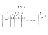
- a yarn winder comprises a one-line frame 61 including a plurality of winding units 1 provided in line and a frame control device 4 which can individually set operational conditions for the winding units 1 and which can monitor each winding unit 1 for its operations.
- the present embodiment will be described in connection with the one line of frame 61.
- plural lines of frames 61 and a higher control device such as a production management device may be connected together so that the control device can transmit and receive data to and from the frames 61.
- the higher control device can centrally manage the frames 61.
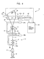
- the winding unit 1 comprises an unwinding assisting device 2, a tensioning device 3 also used as a twist stopping device, a yarn splicing device 5, a slab catcher 6, and a winding drum 7 arranged in this order in a direction in which a yarn Y wound around a yarn supplying package B (yarn supplying body) such as a spinning bobbin is taken up. That is, the automatic winder is configured so that the winding drum 7 is rotated to unwind the yarn Y from the yarn supplying package B, while a package P wound around a bobbin Bf is rotated in contact with the winding drum 7 to wind the yarn Y into the package P.
- the automatic winder is configured so that the winding drum 7 is rotated to unwind the yarn Y from the yarn supplying package B, while a package P wound around a bobbin Bf is rotated in contact with the winding drum 7 to wind the yarn Y into the package P.
- the tensioning device 3 is placed above the yarn supplying package B via the unwinding assisting device 2.
- the tensioning device 3 is of a gate type in which fixed comb teeth 11 alternate with movable comb teeth 12.
- the yarn splicing device 5 executes a yarn splicing process of splicing the cut-off yarn Y on the yarn supplying package B to the yarn Y on the package P.
- the yarn splicing device 5 comprises a yarn splicing device main body 35, a lower yarn sucking and guiding member 36 that guides the yarn Y on the yarn supplying package B to the yarn splicing device main body 35, and an upper yarn sucking and guiding member 37 that guides the yarn Y on the package P to the yarn splicing device main body 35.
- the lower yarn sucking and guiding member 36 has a suction port 36a that can be opened and closed.
- the lower yarn sucking and guiding member 36 can be pivoted around a shaft 36b.
- the suction port 36a is opened.
- the tensioning device 3 also used as the twist stopping device is also opened to suck a supplying-side yarn end into the suction port 36a.
- the suction port 36a holds the yarn end and the lower yarn sucking and guiding member 36 is pivoted from a lower yarn end catching position to an upper yarn end guiding position. Then, the lower end is guided into the yarn splicing main body 35 and into the tensioning device 3.
- the lower yarn sucking and guiding member 36 When the suction port 36a lies between the yarn supplying package B and the tensioning device 3, the lower yarn sucking and guiding member 36 is in a standby position. Accordingly, after being activated, the lower yarn sucking and guiding member 36 can quickly catch the supplying-side yarn end.
- the upper yarn sucking and guiding member 37 has a suction port 37a and can be pivoted around a shaft 37b. When the yarn Y is forcedly cut, the upper yarn sucking and guiding member 37 is pivoted to an upper yarn end catching position. The upper yarn sucking and guiding member 37 uses the suction port 37a to suck a yarn end rewound into the package P. Further, while catching the upper yarn, the upper yarn sucking and guiding member 37 is pivoted downward to guide the upper yarn to the yarn splicing main body 35. The yarn splicing device main body 35 then splices the upper yarn to the lower yarn.
- the slab catcher 6 is, for example, a capacitance-type or optical-type yarn thickness detecting device.
- a signal from the slab catcher 6 is processed using an analyzer (not shown) to detect a yarn defect such as a slab.
- an attached cutter 6a cuts the yarn Y being taken up.
- the yarn splicing device 5 removes the defective part during a yarn splicing process.
- the yarn splicing device 5 splices the yarn Y on the yarn supplying package B to the yarn Y on the package P.
- the winding drum 7 is configured as a traversing drum comprising a traversing groove.
- the winding drum 7 contacts with the package P to rotate it and traverses the yarn Y being rewound into the package P.
- the winding drum 7 is rotatively driven by a motor 41.
- the motor 41 has its rotation speed controlled, via a drum rotation control device 42 , by a control signal outputted by a unit control device 50.
- a drum rotation number measuring sensor 43 is provided near a rotating shaft 41a of the motor 41 to detect the number of rotations of the rotating shaft 41a.
- the drum rotation number measuring sensor 43 outputs a detection signal to the unit control device 50 for every rotation of the rotating shaft 41.
- the bobbin Bf, around which the package P is formed, is rotatably supported by a shaft member 44.
- a package rotation number measuring sensor 45 is provided near the shaft member 44 to detect the number of rotations of the shaft member 44.
- the package rotation number measuring sensor 45 outputs a detection signal to the unit control device 50 for every rotation of the rotating member 44.
- the unit control device 50 comprises a communication section 52 connected to the frame control device 4 so as to enable data communications with the frame control device 4, as well as a total drum rotation number default value storage section 53, a correction value storage section 54, and a total drum rotation number final value storage section 55, and a package total rotation number output section 56 connected to the communication section 52.
- the total drum rotation number default value storage section 53 is a storage area provided in a memory so as to store a total drum rotation number default value transmitted by the frame control device 4.
- the "total drum rotation number default value” means the total number of drum rotations counted when the amount of yarn rewound (package weight) reaches, for example, 400g during while the yarn Y is rewound.
- the weight is not limited to 400g provided that a rewinding operation is being performed.
- the correction value storage section 54 is a storage area provided in the memory so as to store a correction value transmitted by the frame control device 4.
- the total drum rotation number final value storage section 55 is a storage area provided in the memory so as to store a total drum rotation number full package value transmitted by the frame control device 4. If a correction value is stored in the correction value storage section 54, the total drum rotation number final value storage section 55 adds or subtracts the correction value to or from the total drum rotation number full package value and stores the result obtained.
- the "correction value” means a value (the amount of yarn rewound) set to reduce a variation in package weight among the winding unit 1 in each group after rewinding has been completed.
- the “total drum number final value” is the total number of drum rotations required for the final weight of a full package (rewinding completion); with this value, the winding unit 1 is stopped.
- the total package rotation number output section 56 has a function to output the total number of package rotations to the frame control device 4 via the communication section 52 during rewinding and after the rewinding has been completed.
- a total package rotation number counting section 57 is connected to the total package rotation number output section 56.
- the total package rotation number counting section 57 connects to an input and output section 58, a first total drum rotation number comparing section 59, and a second total drum rotation number comparing section 60.
- the input and output section 58 is connected to a total drum rotation number counting section 61.
- the total drum rotation number counting section 61 connects to the first total drum rotation number comparing section 59 and the second total drum rotation number comparing section 60.
- the second total drum rotation number comparing section 60 is connected to the total package rotation number counting section 57 and to the input and output section 58 via a stopping section 62.
- the input and output section 58 has a function to transmit and receive an output and input signals to and from the winding unit main body 51.
- the input and output section 58 has, for example, a function to output a control signal to the drum rotation control device 42 of the winding unit main body 51 to rotate the motor 41 (winding drum 7), a function to receive an input signal from the package rotation number measuring sensor 45 to output the signal to the total package rotation number counting section 57, and a function to receive an input signal from the drum rotation number measuring sensor 43 to output the signal to the total drum rotation number counting section 61.
- the total package rotation number counting section 57 has a function to increment its count every time the package rotation number measuring sensor 45 inputs a detection signal to the total package rotation number counting section 57 via the input and output section 58, to count the total number of rotations of the package P (the total number of package rotations) from start to completion of rewinding, and a function to output the total number of package rotations counted when the section is brought into the data output state, to the total package rotation number output section 56.
- the total drum rotation number counting section 61 has a function to increment its count every time the drum rotation number measuring sensor 43 inputs a detection signal to the total drum rotation number counting section 61 via the input and output section 58, to count the total number of rotations of the winding drum 7 (the total number of drum rotations) from start to completion of rewinding, and a function to output the total number of drum rotations to the first total drum rotation number comparing section 59 and the second total drum rotation number comparing section 60.
- the first total drum rotation number comparing section 59 has a function to compare a total drum rotation number count in the total drum rotation number counting section 61 with a total drum rotation number default value in the total drum rotation number default value storage section 53, and when both values are equal, to set the operational state of the total package rotation number counting section 57 to the data output state.
- the second total drum rotation number comparing section 60 has a function to compare a total drum rotation number count in the total drum rotation number counting section 61 with a total drum rotation number final value in the total drum rotation number final value storage section 55, and when both values are equal, to set the operational state of the total package rotation number counting section 57 to the data output state, while bringing the stopping section 62 into an operative state.
- the stopping section 62 has a function to stop the winding unit main body 51 via the input and output section 58 when activated.
- the total package rotation number output section 56, the total package rotation number counting section 57, the first total drum rotation number comparing section 59, and the first total drum rotation number comparing section 60 may be composed of hardware or software. That is, these sections may be constructed using programs consisting of winding unit operation routines in Figure, so as to provide the same functions.
- the unit control device 50 configured as described above is connected to the frame control section 4 so as to transmit and receive data to and from it.
- the frame control device 4 has a storage section and a central control section (not shown).
- the storage section is composed of a mass storage device and has a correction value setting base table in Figure 6 , a correction calculation table in Figure 7 , and a correction execution table in Figure 8 .
- the correction value setting base table has a "total drum rotation number default value”, a “total drum rotation number full package value”, a “simple correction value”, a “ ⁇ correction value”, a “CV reference value”, and a "warning value” for each yarn type. Data is pre-registered in the correction value setting base table so as to be rewritten as required.
- the “total drum rotation number default value” indicates the total number of drum rotations during rewinding as described above.
- the “total drum rotation number full package value” is obtained when the package P regularly becomes full.
- the "simple correction value” indicates the amount of yarn rewound and is transmitted to the winding unit 1 as a correction value when the total number of package rotations during rewinding deviates from the appropriate value by at least ⁇ 1.2 ⁇ .
- ⁇ is a standard deviation value.
- the threshold is set at ⁇ 1.2 ⁇ but is not limited to this value.
- the " ⁇ correctin value” indicates the amount of yarn rewound which is set on the basis of the relationship between each threshold ⁇ 0.8 ⁇ , ⁇ 1.2 ⁇ , ⁇ 1.6 ⁇ and the total number of package rotations during rewinding. For example, for the yarn type A (GT-30), if the deviation of the total number of package rotation is between + 0.8 ⁇ and + 1.2 ⁇ , "-a4" is transmitted as a correction value. If the diviation of the total number of package rotations is between +1.2 ⁇ and +1.6 ⁇ , "-a5" is transmitted as a correction value. If the total number of package rotations deviates from the appropriate value by at least + 1.6 ⁇ , "-a6" is transmitted as a correction value.
- the "CV reference value" is a threshold compared with the coefficient of variation calculated from the total number of package rotations during rewinding to determined whether or not to carry out the above simple correction and ⁇ correction.
- the "warning value” is a threshold compared with the total number of package rotations in each winding unit 1 during rewinding to determine that a rewinding error is occurring in the winding unit 1 for which the total number of package rotations deviates from the average of the total number of package rotations by at least the warning value.
- the correction calculation table is a data table provided for calculations. As shown in Figure 7 , the correction calculation table has a "group”, a “unit number”, a “total number of drum rotations", an "average value”, a “deviation”, a “standard deviation”, and a “coefficient of variation” so that all of these are rewritable.
- the “group” means an operation unit for a plurality of winding units 1 which is set so as to produce packages P for the same lot.
- the “unit number” is an identification number inherent in the winding unit 1.
- the “total number of package rotations” is the number of rotations of the package P during rewinding.
- the "average value”, the "deviation, the "standard deviation”, and the "coefficient of variation” are calculated on the basis of the total number of package rotations for each group.
- the correction execution table is a data table provided in order to manage the operational status of each group.
- the correction execution table has a "group", a “yarn type", an “automatic correction”, a “total number of drum rotations default value”, a “correction method”, a "simple correction value”, a “ ⁇ correction value”, a “ ⁇ reference value”, and a “warning value”.
- the "automatic correction” is used to set whether or not to carry out automatic corrections. When this is set to "ON”, the correction is permitted. When this is set to "OFF”, the correction is prohibited.
- the “correction method” is used to set whether the simple correction or the ⁇ correction is to be carried out. For example, for the "simple correction”, the “simple correction value” corresponding to the "yarn type” is read from the correction value setting base table in Figure 8 for setting.
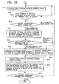
- the central control section of the unit control device 50 is adapted to execute a frame control correcting process routine as shown in Figure 2 .
- the frame control correcting process routine enables the package weight obtained in each winding unit 1 after the completion of rewinding to be predicted on the total numbers of package rotations in the group using the above described table.
- the frame control correcting process routine also corrects the amount of yarn rewound so as to reduce a variation in package weight among the winding units 1 which may remain after the completion of the rewinding.
- the central control section may comprise a function corresponding to the frame control correcting process routine, in hardware form.
- an operator operates the frame control device 4 to display an automatic correction ON/OFF setting screen in Figure 9 .
- the automatic correction ON/OFF setting screen is formed on the basis of the data stored in the correction execution table in Figure 8 . Specifically, groups (GR1, GR2, GR3, ...), yarn types produced by the groups (GT-30, GT-40, GT-12, ...), and an automatic correction setting status (ON, OFF) are displayed (S1) as shown in Figure 9 .
- the switch target group is initialized. Specifically, as shown in Figure 8 , given that the automatic correction for the group G1 has been switched on, the total drum rotation number default value, simple correction value, ⁇ correction value, CV reference value, and warning value corresponding to the yarn type A (GT30) handled by the group G2 are read from the correction value base table in Figure 6 . These values are then stored in the corresponding areas in the correction execution table (S5).
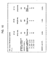
- a correction content setting screen S6 If the operator performs an operation required to display the correction content setting screen (S3, YES), the correction content setting screen in Figure 10 is displayed.
- the correction content setting screen is desirably displayed on condition that a password is inputted. The contents of corrections in the correction content setting screen will be described in detail.
- this screen displays the display items "monitor gram (g)", “automatic correction method”, “correction value”, and “monitor rpm-CV" in association with each group.
- the "monitor gram (g)” indicates the amount of yarn rewound during rewinding from which the total number of package rotations is acquired. This value is normally set at 400g. Then, the total number of drum rotations corresponding to the monitor gram is set as a total drum rotation number default value.
- the "automatic correction method” indicates either the simple correction or the ⁇ correction. Then, the contents of the “automatic correction method” and a correction value set on the basis of the ON/OFF of the automatic correction are displayed.
- the “monitor rpm-CV” displays the coefficient of variation calculated on the basis of the total number of package rotations corresponding to the package weight obtained during rewinding, for example, 400g (S7).
- the winding units 1 of each group are executing the winding unit operation routine as shown in Figure 3 .
- each of the winding units 1 stores the total drum rotation number default value contained in this signal, in the total drum rotation number default value storage section 53 in Figure 1 (G1).
- the operation of the winding unit main body 51 is started to rotate the winding drum 7.
- the yarn Y is wound around the bobbin Bf to obtain the package P (G2).
- the winding detection signals are loaded from the drum rotation number measuring sensor 43 and package rotation number measuring sensor 45 as shown in Figure 1 .
- the total drum rotation number counting section 61 and the total package rotation number counting section 57 counts up the total number of drum rotations and the total number of package rotations, respectively.
- the frame control device 4 is ready to receive the total package rotation number signal from each winding unit 1 (S11). On receiving the total package rotation number signal from each winding unit 1, the frame control device 4 extracts the total package rotation number count contained in the signal as the total number of package rotations. Then, the frame control device 4 stores the total number of package rotations in the correction calculation table in Figure 7 in the storage area for the total number of package rotations corresponding to the unit number of the winding unit 1. Then, it is determined whether or not the total numbers of package rotations have been obtained from all the winding units 1 of the group (S12).
- step S12 it is determined whether or not the total numbers of package rotations have been obtained from all the winding units 1 of the group.
- the present invention is not limited to this aspect. It may be determined whether or not the total numbers of package rotations have been obtained from a certain span or from a certain number, for example, about two winding units 1 within the group.
- the group correction mode that is, the automatic correction has been turned on (S13). If the automatic correction has been turned on (S13, YES), then as shown in Figure 7 , the average, deviation, standard deviation, and coefficient of variation of the total numbers of package rotations in the group are calculated (S14). Subsequently, it is determined whether or not the coefficient of variation is smaller than the CV reference value of 2% or the like (S15). If the coefficient of variation is not smaller than the CV reference value (S15, NO), the correction is determined to be effective in suppressing a variation.
- the correction value corresponding to the correction method is transmitted to each of the winding units 1 in the group (S16). If the group correction mode has not been turned on (S13, NO) and the coefficient of variation is smaller than the CV reference value (S15, YES), the correction value of "0" is transmitted to all the winding units 1 in the group so as to avoid carrying out the correction.
- a total package rotation number graph window is subsequently displayed all over or in a part of the display screen.
- the window directly and indirectly shows, in a graph, the total number of package rotations in each of the winding units 1 in the group.
- the window screen is separated into an upper display area and a lower display area.
- a bar graph shows the relationship between the unit number of the winding unit 1 and the total number of package rotations.
- a bar graph shows the relationship between the unit number of the winding unit 1 and the average value.
- the graph display may be direct or indirect (S18). Then, by viewing the total package rotation number graph window, the operator can predict the weight of the full package obtained after rewinding has been completed, on the basis of the strong correlation between the total number of package rotations during the rewinding and the weight of the full package.
- the frame control device determines the absolute value of the difference between the total number of package rotations for each winding unit 1 and the average of the total numbers of package rotations for all the winding units 1 in the group. Then, winding units 1 are identified for which the absolute value of the difference is larger than the warning value.
- the graph for each of the identified winding units 1 is then provided with a warning display having a particular color or particular characters. The operator can thus easily identify winding units 1 for which the total number of package rotations deviates from the average total package rotation number by at least a predetermined value. The operator can then recognize that these winding units 1 are performing an erroneous rewinding operation (S19).
- the correction value may be calculated every time package data on a certain number of winding units is updated.
- the weight of a full package in each winding unit 1 can be predicted using a method of predicting the weight of a package in an automatic wider having a large number of winding units 1 arranged in line to execute a rewinding process of rotating the winding drum 7 to rewind a yarn from the yarn supplying package B (yarn supplying bobbin B) to obtain the package P, wherein the weight of the full package in each winding unit 1 can be predicted on the basis of the total number of package rotations when the total number of rotations of the winding drum 7 continuously counted from the start of winding reaches a value corresponding to a predetermined package weight during the rewinding.
- the package weight obtained after the completion of rewinding can be predicted during the rewinding. This makes it possible to quickly complete corrections such as an increase in the amount of yarn rewound which corrections are carried out to obtain the desired package, compared to the prior art, in which the package weight is actually measured after the rewinding has been completed. Further, by reducing a variation in weight among the packages in each lot, it is possible to control the rewinding so as to reduce differences from the average of the package weights within the lot.
- the package P can be produced using a method of manufacturing a package in an automatic wider having a large number of winding units 1 arranged in line to execute a rewinding process of rotating the winding drum 7 to rewind a yarn from the yarn supplying package B to obtain the winding package P, the method comprising, for all the winding units 1, acquiring the total number of package rotations when the total number of rotations of the winding drum continuously counted from the start of winding reaches a value corresponding to a predetermined package weight during the rewinding, and on the basis of the total numbers of package rotations, correcting the amount of yarn rewound so as to reduce a variation in package weight among the winding unit 1 when the packages are full.
- a yarn winder that can realize the method of predicting the weight of the package P has a plurality of winding units 1 each of which executes a rewinding process of rotating the winding drum 7 to rewind the yarn Y around the bobbin Bf to obtain the package P and the frame control device 4 which can control and manage the rewinding process executed on each group of winding units 1.
- the frame control device 4 has package total rotation number acquiring means (S11 and S12 in Figure 2 ) for acquiring, for all the winding units 1, the total number of package rotations when the total number of rotations of the winding drum 7 continuously counted from the start of winding reaches a value corresponding to a predetermined package weight during the rewinding, and variation determining means (S14 in Figure 2 ) for determining a variation in package weight among the winding units 1 in the group on the basis of the total numbers of package rotations.
- package total rotation number acquiring means S11 and S12 in Figure 2
- variation determining means for determining a variation in package weight among the winding units 1 in the group on the basis of the total numbers of package rotations.
- the yarn winder has rewinding amount correcting means (S16 in Figure 2 ) for correcting the amount of yarn rewound for each winding unit 1 on the basis of the variation in package weight determined by the variation determining means so as to reduce a variation in package weight which may remain after the rewinding has been completed.
- the yarn winder further has variation coefficient determining means (S17) for determining a coefficient of variation among the winding units 1 in the group on the basis of the total numbers of package rotations and if the coefficient of variation is less than a predetermined value, prohibiting the rewinding amount correcting means from correcting the amount of yarn rewound. It is thus possible to determine the degree of deviation using the coefficient of variation to prevent the correction of the amount of yarn rewound from being uselessly carried out even though they are actually not effective.
- the yarn winder further has variation displaying means (S18 in Figure 2 ) for directly and/or indirectly displaying, in a graph (the total package rotation number graph window in Figure 11 ), the total number of package rotations for each of the winding units 1 in the group.
- This configuration enables the operator to easily understand the degree of the deviation of the total number of package rotations in each winding unit 1. It is thus possible to facilitate the prediction of the weight of the full package described above. Additionally and as shown in Figure 11 , the total number of package rotations is displayed in a graph so that the operator can visually determine the deviation to accomplish the prediction.
- the present invention is not limited to this aspect.
- a variation in the total number of package rotations may be expressed as numeral values and a predicted value for the weight of the full package may be displayed.
- the yarn winder further has error notifying means (19 in Figure 2 ) for identifying a winding unit 1 for which the total number of package rotations deviates, by at least a predetermined value, from an average of the total numbers of package rotations for all the winding units 1 in the group and notifying an operator of this winding unit 1.
- the program composed of the routines according to the present embodiment may be pre-written in a ROM in the storage section so as to be only readable.
- the program may be recorded in a recording medium such as a CD and may be read and written in the storage section as required.
- the program may be written in the storage section by being transmitted via an electric communication line such as the Internet.
- the present invention is applicable to applications in which packages involving significant errors in the weight of the full package are manufactured.
Landscapes
- Engineering & Computer Science (AREA)
- Quality & Reliability (AREA)
- Filamentary Materials, Packages, And Safety Devices Therefor (AREA)
Claims (8)
- Verfahren zur Herstellung einer Auflaufspule (P) in einem Spulautomaten mit einer großen Anzahl von Spulstellen (1), die auf einer Linie angeordnet sind, um einen Spulvorgang durch Drehen einer Spultrommel (7) in jeder Spulstelle (1) durchzuführen, wobei sich die Spultrommel (7) mit der Auflaufspule (P) in Kontakt dreht, die um eine Hülse (Bf) gespult wird, um den Faden (Y) von einer Fadenlieferspule (B) zur Bildung der Auflaufspule abzuspulen,
dadurch gekennzeichnet, dass:für jede Spulstelle die Gesamtzahl der Auflaufspulendrehungen erfasst wird, wenn die Gesamtzahl der Drehungen der Spultrommel (7) kontinuierlich gezählt vom Beginn des Spulvorgangs aus einen Wert entsprechend einem bestimmten Auflaufspulengewicht während des Abspulens erreicht, undauf der Grundlage der Gesamtzahl von Auflaufspulendrehungen die in jeder Spulstelle (1) abgespulte Fadenmenge so korrigiert wird, dass eine Änderung des Auflaufspulengewichts zwischen den Spulstellen reduziert wird, wenn die Auflaufspulen (P) voll sind. - Verfahren zur Herstellung einer Auflaufspule nach Anspruch 1,
dadurch gekennzeichnet, dass
die abgespulte Fadenmenge auf der Grundlage einer Standardabweichung der Gesamtzahl von Auflaufspulendrehungen während des Abspulens korrigiert wird. - Fadenspulmaschine mit wenigstens einer aus mehreren Spulstellen (1) bestehenden Gruppe, von denen jede einen Abspulvorgang durch Drehen einer Spultrommel (7) durchführt, um einen Faden von einer Fadenlieferspule abzuspulen und eine Auflaufspule (P) zu erhalten, wobei sich die Spultrommel (7) in Kontakt mit der Auflaufspule (P) dreht, und einem Maschinensteuergerät (4), das den Abspulvorgang, der in jeder Gruppe von Spulstellen durchgeführt wird, steuern und verwalten kann,
dadurch gekennzeichnet, dass
das Maschinensteuergerät (4) aufweist:eine Gesamtdrehzahlerfassungseinrichtung zum Erfassen der Gesamtzahl von Auflaufspulendrehungen für jede Spulstelle (1), wenn die Gesamtzahl der Drehungen jeder Spultrommel (7), kontinuierlich gezählt vom Beginn des Spulvorgangs an, einen Wert entsprechend einem bestimmten Auflaufspulengewicht während des Abspulens erreicht, undeine Änderungsbestimmungseinrichtung zur Bestimmung einer Änderung des Auflaufspulengewichts zwischen den Spulstellen in der Gruppe auf der Grundlage der Gesamtzahlen von Auflaufspulendrehungen in jeder Spulstelle. - Fadenspulmaschine nach Anspruch 3,
dadurch gekennzeichnet, dass
die Änderungsbestimmungseinrichtung die Abweichung von einer Standardabweichung der Gesamtzahl von Auflaufspulendrehungen bestimmt. - Fadenspulmaschine nach Anspruch 3,
dadurch gekennzeichnet, dass
das Maschinensteuergerät (4) aufweist:eine Abspulmengenkorrektureinrichtung zur Korrektur der für jede Spulstelle abgespulten Fadenmenge auf der Grundlage der Änderung des Auflaufspulengewichts, das von der Änderungsbestimmungseinrichtung bestimmt wird, um die Änderung des Auflaufspulengewichts zu reduzieren, die verbleiben kann, nachdem der Abspulvorgang beendet wurde. - Fadenspulmaschine nach Anspruch 5,
dadurch gekennzeichnet, dass
das Maschinensteuergerät (4) aufweist:eine Änderungskoeffizientenbestimmungseinrichtung zur Bestimmung eines Änderungskoeffizienten zwischen den Spulstellen in der Gruppe auf der Grundlage der Gesamtanzahlen von Auflaufspulendrehungen, und, wenn der Änderungskoeffizient geringer als eine bestimmte Größe ist, die Abspulmengenkorrektureinrichtung daran zu hindern, die abgespulte Fadenmenge zu korrigieren. - Fadenspulmaschine nach einem der Ansprüche 3 bis 6,
dadurch gekennzeichnet, dass
das Maschinensteuergerät (4) aufweist:eine Änderungsanzeigeeinrichtung zur direkten und/oder indirekten Anzeige der Gesamtzahl von Auflaufspulendrehungen für jede Spulstelle in der Gruppe in einem Diagramm. - Fadenspulmaschine nach Anspruch 7,
dadurch gekennzeichnet, dass
das Maschinensteuergerät (4) aufweist:eine Fehlerinformationseinrichtung zur Identifizierung einer Spulstelle, für die die Gesamtzahl der Auflaufspulendrehungen um wenigstens eine bestimmte Größe von einem Mittelwert der Gesamtzahlen von Auflaufspulendrehungen für alle Spulstellen in der Gruppe abweicht, und zum Informieren eines Bedieners über diese Spulstelle.
Applications Claiming Priority (4)
| Application Number | Priority Date | Filing Date | Title |
|---|---|---|---|
| JP2003277233 | 2003-07-22 | ||
| JP2003277233 | 2003-07-22 | ||
| JP2003351010 | 2003-10-09 | ||
| JP2003351010A JP4192746B2 (ja) | 2003-07-22 | 2003-10-09 | パッケージの重量予測方法、パッケージの製造方法および糸条巻取機 |
Publications (3)
| Publication Number | Publication Date |
|---|---|
| EP1500619A2 EP1500619A2 (de) | 2005-01-26 |
| EP1500619A3 EP1500619A3 (de) | 2005-06-22 |
| EP1500619B1 true EP1500619B1 (de) | 2008-08-27 |
Family
ID=33492500
Family Applications (1)
| Application Number | Title | Priority Date | Filing Date |
|---|---|---|---|
| EP20040016735 Expired - Lifetime EP1500619B1 (de) | 2003-07-22 | 2004-07-15 | Verfahren und Vorrichtung zum Herstellen einer Garnspule |
Country Status (4)
| Country | Link |
|---|---|
| EP (1) | EP1500619B1 (de) |
| JP (1) | JP4192746B2 (de) |
| CN (1) | CN100439225C (de) |
| DE (1) | DE602004016083D1 (de) |
Families Citing this family (3)
| Publication number | Priority date | Publication date | Assignee | Title |
|---|---|---|---|---|
| JP2013241232A (ja) * | 2012-05-18 | 2013-12-05 | Murata Machinery Ltd | 糸巻取装置 |
| CN111060418B (zh) * | 2019-12-16 | 2022-08-02 | 广东溢达纺织有限公司 | 纱线干涩判断方法 |
| JP7844205B2 (ja) * | 2022-03-18 | 2026-04-13 | Tmtマシナリー株式会社 | 糸加工設備 |
Family Cites Families (7)
| Publication number | Priority date | Publication date | Assignee | Title |
|---|---|---|---|---|
| DE2216960B2 (de) * | 1971-04-09 | 1977-04-14 | Nippon Seren Co. Ltd., Kawasaki, Kanagawa (Japan) | Fadenlaengenmessvorrichtung |
| US3739996A (en) * | 1971-06-29 | 1973-06-19 | Murata Machinery Ltd | Measuring apparatus of total yarn length wound in package on a yarn winder |
| DE2460252C2 (de) * | 1974-12-19 | 1986-09-04 | W. Schlafhorst & Co, 4050 Mönchengladbach | Verfahren zum Herstellen von Textilspulen vorgegebener Fadenlänge |
| CH663402A5 (de) * | 1981-12-04 | 1987-12-15 | Loepfe Ag Geb | Verfahren zum bestimmen der auf eine kreuzspule mit reibantrieb durch eine nutentrommel aufgewickelten garnlaenge. |
| JPS58119560A (ja) * | 1981-12-29 | 1983-07-16 | Aichi Boseki Kk | 定量チ−ズの自動形成方法および装置 |
| JP2806899B2 (ja) * | 1995-11-17 | 1998-09-30 | 日特エンジニアリング株式会社 | 線条材の巻取装置 |
| DE10118659A1 (de) * | 2001-04-14 | 2002-10-17 | Schlafhorst & Co W | Spulstelle einer Textilmaschine |
-
2003
- 2003-10-09 JP JP2003351010A patent/JP4192746B2/ja not_active Expired - Fee Related
-
2004
- 2004-07-15 EP EP20040016735 patent/EP1500619B1/de not_active Expired - Lifetime
- 2004-07-15 DE DE200460016083 patent/DE602004016083D1/de not_active Expired - Fee Related
- 2004-07-22 CN CNB2004100544581A patent/CN100439225C/zh not_active Expired - Fee Related
Also Published As
| Publication number | Publication date |
|---|---|
| JP2005053695A (ja) | 2005-03-03 |
| CN1576218A (zh) | 2005-02-09 |
| EP1500619A2 (de) | 2005-01-26 |
| CN100439225C (zh) | 2008-12-03 |
| EP1500619A3 (de) | 2005-06-22 |
| JP4192746B2 (ja) | 2008-12-10 |
| DE602004016083D1 (de) | 2008-10-09 |
Similar Documents
| Publication | Publication Date | Title |
|---|---|---|
| US4984749A (en) | Operation controlling method for textile machine | |
| EP2690046B1 (de) | Garndefektdetektionsvorrichtung und Wickelvorrichtung | |
| EP2700602B1 (de) | Garnaufwickelvorrichtung, automatische spulmaschine und textilmaschine | |
| EP2433889B1 (de) | Garnwicklungsvorrichtung und verfahren zur alarmschwellenwertbestimmung zur erkennung von fehldrehungen in einem paket | |
| EP2017212B1 (de) | Garnwicklungsvorrichtung | |
| EP2690048B1 (de) | Garnwicklungsmaschine | |
| JP2013241232A (ja) | 糸巻取装置 | |
| EP2671983B1 (de) | Garnwickelvorrichtung und Garnwickelverfahren | |
| EP2690047B1 (de) | Garnwicklungsmaschine | |
| EP1500619B1 (de) | Verfahren und Vorrichtung zum Herstellen einer Garnspule | |
| EP2343261A2 (de) | Garnwickelmaschine und Garnwickelverfahren | |
| JPH0134673B2 (de) | ||
| EP1460016B1 (de) | Verfahren zum Betreiben einer automatische Spulmaschine | |
| JP2907078B2 (ja) | 定量糸条巻取装置 | |
| JP4787404B2 (ja) | 綾巻きボビンの直径を算出する方法 | |
| JP2002308529A (ja) | 欠陥箇所切除による洗糸方法および洗糸装置 | |
| EP4397609A1 (de) | Garnwickelvorrichtung und automatischer wickler | |
| JP2694736B2 (ja) | 糸条の巻取機 | |
| JP2018162137A (ja) | 糸巻取機 | |
| CN113979220A (zh) | 纱线卷取机以及卷取异常检测方法 | |
| JPS61221060A (ja) | 糸条巻取機の異常監視装置 | |
| JPH01192676A (ja) | ワインダーにおける混番検出方法 | |
| JPH0881132A (ja) | 糸の巻取り量制御方法 | |
| JP2003053426A (ja) | 線材のもつれ検出方法および前記検出方法を用いた線材の巻き替え方法 |
Legal Events
| Date | Code | Title | Description |
|---|---|---|---|
| PUAI | Public reference made under article 153(3) epc to a published international application that has entered the european phase |
Free format text: ORIGINAL CODE: 0009012 |
|
| AK | Designated contracting states |
Kind code of ref document: A2 Designated state(s): AT BE BG CH CY CZ DE DK EE ES FI FR GB GR HU IE IT LI LU MC NL PL PT RO SE SI SK TR |
|
| AX | Request for extension of the european patent |
Extension state: AL HR LT LV MK |
|
| PUAL | Search report despatched |
Free format text: ORIGINAL CODE: 0009013 |
|
| AK | Designated contracting states |
Kind code of ref document: A3 Designated state(s): AT BE BG CH CY CZ DE DK EE ES FI FR GB GR HU IE IT LI LU MC NL PL PT RO SE SI SK TR |
|
| AX | Request for extension of the european patent |
Extension state: AL HR LT LV MK |
|
| 17P | Request for examination filed |
Effective date: 20050826 |
|
| AKX | Designation fees paid |
Designated state(s): DE IT |
|
| 17Q | First examination report despatched |
Effective date: 20060420 |
|
| 17Q | First examination report despatched |
Effective date: 20060420 |
|
| RTI1 | Title (correction) |
Free format text: METHOD OF MANUFACTURING PACKAGE, AND YARN WINDER |
|
| GRAP | Despatch of communication of intention to grant a patent |
Free format text: ORIGINAL CODE: EPIDOSNIGR1 |
|
| GRAJ | Information related to disapproval of communication of intention to grant by the applicant or resumption of examination proceedings by the epo deleted |
Free format text: ORIGINAL CODE: EPIDOSDIGR1 |
|
| GRAP | Despatch of communication of intention to grant a patent |
Free format text: ORIGINAL CODE: EPIDOSNIGR1 |
|
| GRAS | Grant fee paid |
Free format text: ORIGINAL CODE: EPIDOSNIGR3 |
|
| GRAA | (expected) grant |
Free format text: ORIGINAL CODE: 0009210 |
|
| AK | Designated contracting states |
Kind code of ref document: B1 Designated state(s): DE IT |
|
| REF | Corresponds to: |
Ref document number: 602004016083 Country of ref document: DE Date of ref document: 20081009 Kind code of ref document: P |
|
| PLBE | No opposition filed within time limit |
Free format text: ORIGINAL CODE: 0009261 |
|
| STAA | Information on the status of an ep patent application or granted ep patent |
Free format text: STATUS: NO OPPOSITION FILED WITHIN TIME LIMIT |
|
| 26N | No opposition filed |
Effective date: 20090528 |
|
| PG25 | Lapsed in a contracting state [announced via postgrant information from national office to epo] |
Ref country code: DE Free format text: LAPSE BECAUSE OF NON-PAYMENT OF DUE FEES Effective date: 20100202 |
|
| PG25 | Lapsed in a contracting state [announced via postgrant information from national office to epo] |
Ref country code: IT Free format text: LAPSE BECAUSE OF NON-PAYMENT OF DUE FEES Effective date: 20090715 |