EP1500615B1 - Dispositif de transport à courroie avec un dispositif d'étanchéité - Google Patents
Dispositif de transport à courroie avec un dispositif d'étanchéité Download PDFInfo
- Publication number
- EP1500615B1 EP1500615B1 EP04006397A EP04006397A EP1500615B1 EP 1500615 B1 EP1500615 B1 EP 1500615B1 EP 04006397 A EP04006397 A EP 04006397A EP 04006397 A EP04006397 A EP 04006397A EP 1500615 B1 EP1500615 B1 EP 1500615B1
- Authority
- EP
- European Patent Office
- Prior art keywords
- belt
- belt conveyor
- conveyor device
- barrier
- lower edge
- Prior art date
- Legal status (The legal status is an assumption and is not a legal conclusion. Google has not performed a legal analysis and makes no representation as to the accuracy of the status listed.)
- Expired - Lifetime
Links
- 238000007789 sealing Methods 0.000 title claims description 46
- 239000000463 material Substances 0.000 claims description 28
- 230000004888 barrier function Effects 0.000 claims description 25
- 239000007787 solid Substances 0.000 claims description 11
- 229920001971 elastomer Polymers 0.000 claims description 6
- 239000002184 metal Substances 0.000 claims description 6
- 239000005060 rubber Substances 0.000 claims description 4
- 239000004033 plastic Substances 0.000 claims description 3
- 239000000806 elastomer Substances 0.000 claims description 2
- 230000000903 blocking effect Effects 0.000 description 24
- 239000000470 constituent Substances 0.000 description 3
- 230000008719 thickening Effects 0.000 description 3
- 230000007257 malfunction Effects 0.000 description 2
- 239000004566 building material Substances 0.000 description 1
- 239000013590 bulk material Substances 0.000 description 1
- 230000009194 climbing Effects 0.000 description 1
- 230000009969 flowable effect Effects 0.000 description 1
- 238000007790 scraping Methods 0.000 description 1
- 210000002105 tongue Anatomy 0.000 description 1
Images
Classifications
-
- B—PERFORMING OPERATIONS; TRANSPORTING
- B65—CONVEYING; PACKING; STORING; HANDLING THIN OR FILAMENTARY MATERIAL
- B65G—TRANSPORT OR STORAGE DEVICES, e.g. CONVEYORS FOR LOADING OR TIPPING, SHOP CONVEYOR SYSTEMS OR PNEUMATIC TUBE CONVEYORS
- B65G21/00—Supporting or protective framework or housings for endless load-carriers or traction elements of belt or chain conveyors
- B65G21/20—Means incorporated in, or attached to, framework or housings for guiding load-carriers, traction elements or loads supported on moving surfaces
- B65G21/2045—Mechanical means for guiding or retaining the load on the load-carrying surface
- B65G21/2063—Mechanical means for guiding or retaining the load on the load-carrying surface comprising elements not movable in the direction of load-transport
- B65G21/2072—Laterial guidance means
- B65G21/2081—Laterial guidance means for bulk material, e.g. skirts
Definitions
- the invention relates to a belt conveyor specified in the preamble of claim 1 Art.
- belt conveyors are used to convey bituminous or concrete material from a bunker.
- the conveyor line can rise in the conveying direction.
- This conveyed material contains solid components of different sizes, is flowable, and tends to adhere.
- belt conveyor devices are stopped on a case-by-case basis, although conveyed goods are located in the charging area or bunker. Therefore, it must be ensured that lateral boundaries prevent flow of the conveyed material, and also a sealing device is provided which acts transversely to the direction of belt travel and prevents the conveyed away from the direction of tape travel.
- a barrier is provided which, for example, is a stationary sheet-metal wall and forms a relatively narrow sealing gap with the belt surface in the region of a belt-guiding part located below the belt.
- the sealing gap is dimensioned as narrow as possible in order to prevent, for example, at a standstill of the belt, conveyed material emerges against the direction of belt travel.
- the sealing gap width can not be chosen optimally small in this concept, because the belt thickness may not be consistent, and because foreign matter or components of the conveyed can adhere to the belt and then jammed in the direction of belt travel in the sealing gap.
- a flexible aprons are arranged on three sides of a filling chute, which is directed towards the surface of the band, which contact the surface of the band and prevent the escape of bulk material to the outside or against the conveying direction.
- the invention has for its object to provide a belt conveyor in which a durable, trouble-free and effective seal against the escape of conveyed is possible.
- the belt conveyor operates without interference because the blocking element can be temporarily deflected as required and passes through an object or component of the conveyed material or a belt thickening, but immediately returns after passage and restores the narrow sealing gap, so that hardly any conveyed material escapes in an uncontrolled manner.
- the sealing device is also very effective because of the deflectability of the locking element, the actual sealing gap can be set extremely narrow, so that even relatively low-viscosity material does not escape.
- the blocking element even contacts the belt surface.
- the passage opening either passes through the belt width, or it is longer or shorter than the belt width.
- the blocking element may be in one piece, or consist of several adjacent segments.
- the blocking element is intercepted opposite to the deflection at a stop which limits the sealing gap width.
- the stop holds together with the burden of the locking element, the blocking element always in the correct position in which the desired sealing gap width is maintained.
- the locking element Upon passage of a belt thickening and / or a solid component, the locking element is temporarily deflected to subsequently return immediately under the load back to the predetermined by the stop, correct position. If the stop is adjustable, the sealing gap width can be changed as desired.
- the sealing gap width is selected in accordance with the size of the solid constituents of the conveyed material and / or the consistency of the conveyed material, suitably smaller than the smallest component size.
- Such a narrow sealing gap is completely uncritical in terms of disturbances, because the blocking element is deflected in whole or with only one segment, if this should be necessary to avoid interference, however, generates at not deflected blocking element or segment of the narrow sealing gap an excellent sealing against the Outflow of conveyed goods.
- the barrier is expediently a transverse wall of sheet metal, rubber or an elastomer having a lower edge, for example, approximately parallel to the belt surface, which is located at a sufficiently large distance from the belt surface.
- the blocking element is a flap with a locking leg arranged adjacent to the lower edge of the barrier and is pivotable or displaceable when deflected against the restoring load.
- the pivotable mounting of the locking leg offers the advantage of a precisely maintainable intermediate distance or light contact pressure between the locking leg and the barrier.
- a movable storage is structurally particularly simple.
- the locking leg is arranged on the side of the passage opening facing away from a storage area of the barrier because it can be easily deflected in this position, even under the dynamic pressure of the conveyed material.
- this does not preclude arranging the locking leg on the other side of the barrier.
- the locking leg should be higher than the width of the passage opening in any case.
- the locking leg should have a webbing surface at least substantially parallel lower wiper edge.
- the wiping edge can be straight.
- the wiping edge should be adapted to the trough shape.
- the locking leg is arranged on a pivoting part, which is supported in a pivot bearing, wherein the stop engages the pivoting part or an extension of the pivoting part.
- a pivotable blocking element of the locking leg should face the lower edge of the barrier have an arc of curvature whose arc center is at least approximately in the pivot axis. In this way, a good seal between the locking leg and the lower edge of the barrier is generated at the deflection thereof, regardless of the respective pivot position of the locking leg.
- a sealing lip or the like Provided on the lower edge, which cooperates with the locking legs.
- a ballast and / or a spring arrangement may be provided which loads the locking element in the direction of the stop.
- At least the locking leg should be a sheet metal or plastic molded part, which is optionally disloyal liable for the conveyed.
- the pivoting part forms a contact surface which, preferably, with the belt surface defines a wedge-shaped inlet gap. Due to the wedge shape of the inlet gap a entrained solid component of the conveyed material can deflect the blocking element very easily.
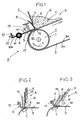
- a belt conveyor B shown in FIG. 1 is, for example, part of a climbing or flat conveying device in a paver or feeder to convey conveyed material G, for example, from a bunker (feed area), not shown, to a delivery area.
- the belt conveyor B is equipped with a sealing device A, which is intended to prevent the conveyed material G from leaking uncontrollably opposite to the conveying direction during operation and / or at standstill of the belt conveyor device.
- the conveyed material G contains solid constituents C and is, for example, a bituminous or a concrete building material for producing traffic areas. Such conveyed material G is free-flowing and tends to adhere.
- the constituents C may, for example, be solid grains in different grain sizes.
- a belt-conveying part 1 can be seen here a pulley 2, around which a belt 3 with its inner belt surface 3b and in fixed Assignment to the sealing device A is performed.
- the conveyed material G is conveyed in the direction of the arrow 4.
- the sealing device A has a transverse to the direction of webbing barrier 5, for example, a sheet or rubber wall whose lower, for example substantially to the belt top 3a parallel or running with any geometry lower edge 7 is arranged at a significant distance from the belt top 3 and with this a passage opening 6 limited.
- the width of the passage opening 6 is suitably larger than the largest component size.
- the passage opening 6 may be as long as the belt width, or shorter or longer.
- the barrier 5 delimits at its in Fig. 1 right side a storage space for the material G.
- a blocking element S is provided, which in the embodiment shown in FIG. 1, an integral pivotable flap with an arcuate curved locking leg 9, a pivot part 10 and a pivot part extension 10a.
- the blocking element S is deflectable in a stationary pivot bearing 11 about an approximately parallel to the axis of the guide roller 2 pivot axis 8 against the load of a spring 14 (and / or a ballast) from the position shown by the belt top 3a away.
- the locking leg 9 is wider than the width of the passage opening 7.
- the locking leg 9 strips with its front side 15 at the lower edge 7 or is associated with this with close spacing.
- the pivot part extension 10a engages a stationary stop 12, which determines the sealing position shown in Fig. 1 of the locking element S.
- the pivoting part 10 forms with its underside a contact surface 18.
- the locking leg 9 ends at the bottom in a scraping edge 16 which extends at least approximately parallel to the belt top 3a and the belt top 3a a narrow sealing gap 17 limited ,
- the wiper edge 16 even touches the belt top side 3a, depending on the setting of the stopper 12.
- the blocking element S has a plurality of adjacent, also individually deflectable segments.
- the blocking element S or at least the locking leg 9 may be a sheet-metal or plastic molded part or consist of several molded parts (segments).
- the blocking element S is displaceably guided approximately parallel to the barrier 5. Between the locking leg 9 of the locking element S and the barrier 5, a rubber plate 19 may be provided, which projects into the passage opening 6 and is pressed against the locking leg 9 by the back pressure of the conveyed material G.
- a rubber plate 19 may be provided between the locking leg 9 of the locking element S and the barrier 5.
- the cross section of the blocking element S is here, for example, J-shaped. This locking element S could consist of individually displaceable and resettable segments.
- the barrier 5 and the locking leg 9 are aligned substantially perpendicular to the belt surface 3a.
- the barrier 5 and the locking leg 9 are inclined, such that the sliding movement of the locking element S (or the respective Segments) with a movement component in the direction of belt travel, which facilitates the deflection and possibly also the return of the locking element S under the force of the spring 14.
- the blocking element S (contact surface 18) expediently forms a wedge-shaped inlet gap with the belt surface 3a.
- the storage and the stop for the blocking element could also be attached to the barrier 5.
- the locking leg 9 could also be located on the other side of the barrier 5.
Landscapes
- Engineering & Computer Science (AREA)
- Mechanical Engineering (AREA)
- Auxiliary Methods And Devices For Loading And Unloading (AREA)
Claims (15)
- Transporteur à bande (B), en particulier pour matières coulantes (G) avec des constituants solides (C), comportant un dispositif d'étanchéité (A), dans lequel est prévue une barrière d'accumulation des matières (5) stationnaire, orientée perpendiculairement au sens de défilement (4) de la bande et munie d'un bord inférieur (7) situé à distance d'une face supérieure (3a) de la bande, et comportant une fente d'étanchéité (17) qui est orientée perpendiculairement au sens de défilement (4) de la bande et qui est adjacente à la face supérieure (3a), opposée à la pièce (1) faisant défiler la bande, caractérisé en ce qu'une ouverture de passage (6) est prévue entre la barrière (5) et la face supérieure (3a) de la bande, et en ce que l'ouverture de passage (6) est fermée par un élément de fermeture (S), qui est mobile dans une direction de déviation par rapport à la barrière (5) et le bord inférieur (7) de celle-ci et qui forme la fente d'étanchéité (17) proprement dite avec la face supérieure (3a) de la bande, et qui peut être dévié pour s'écarter de la face supérieure (3a) de la bande et est sollicité dans le sens opposé à la direction de déviation.
- Transporteur à bande selon la revendication 1, caractérisé en ce que l'ouverture de passage (6) couvre toute la largeur de la bande.
- Transporteur à bande selon la revendication 1, caractérisé en ce que l'élément de fermeture (S) est formé par plusieurs segments juxtaposés et, le cas échéant, mobiles les uns par rapport aux autres.
- Transporteur à bande selon la revendication 1, caractérisé en ce que l'élément de fermeture (S), dans le sens opposé à la direction de déviation, est arrêté par une butée (12), qui est de préférence réglable et qui limite la largeur de la fente d'étanchéité (17).
- Transporteur à bande selon la revendication 1, caractérisé en ce que la largeur de la fente d'étanchéité est ajustée à la taille des constituants solides (C) de la matière transportée (G), de préférence est inférieure à la plus petite taille d'un constituant.
- Transporteur à bande selon la revendication 1, caractérisé en ce que la barrière (5) est une paroi transversale, de préférence en tôle, caoutchouc ou élastomère, comportant un bord inférieur (7), et l'élément de fermeture (S) est un abattant monté pivotant ou coulissant et comportant une branche de fermeture (9) agencée à proximité du bord inférieur (7).
- Transporteur à bande selon la revendication 6, caractérisé en ce que le bord inférieur (7) est au moins sensiblement parallèle à la face supérieure (3a) de la bande.
- Transporteur à bande selon la revendication 6, caractérisé en ce que la branche de fermeture (9) est agencée sur le côté de l'ouverture de passage (6), qui est opposé à la zone d'accumulation des matières de la barrière (5).
- Transporteur à bande selon la revendication 6, caractérisé en ce que la branche de fermeture (9) a une hauteur supérieure à la largeur de l'ouverture de passage (6).
- Transporteur à bande selon la revendication 6, caractérisé en ce que la branche de fermeture (9) comporte un bord de raclage (16) inférieur, au moins sensiblement parallèle à la face supérieure (3a) de la bande.
- Transporteur à bande selon la revendication 6, caractérisé en ce que la branche de fermeture (9) est agencée sur un élément pivotant (10), qui est monté dans un palier de pivotement (11), avec un axe de pivotement au moins sensiblement parallèle à la face supérieure (3a) de la bande, et à distance de la barrière (5), et en ce que, de préférence, la butée (12) est orientée vers l'élément pivotant (10) ou un prolongement (10a) de l'élément pivotant (10).
- Transporteur à bande selon la revendication 6, caractérisé en ce que la branche de fermeture (9), du côté orienté vers le bord inférieur (7), comporte une courbure en arc dont le centre de courbure est situé sensiblement dans l'axe de pivotement du palier de pivotement (11).
- Transporteur à bande selon la revendication 1, caractérisé en ce que l'élément de fermeture (S) est sollicité contre la butée (12) par un lest et/ou un système à ressort (14).
- Transporteur à bande selon la revendication 6, caractérisé en ce qu'au moins la branche de fermeture (9) de l'élément de fermeture (S) est une pièce profilée en tôle ou matière plastique.
- Transporteur à bande selon la revendication 11, caractérisé en ce que l'élément pivotant (10) forme une surface de butée (18) qui, de préférence, délimite conjointement avec la face supérieure (3a) de la bande une fente d'admission conique.
Applications Claiming Priority (2)
| Application Number | Priority Date | Filing Date | Title |
|---|---|---|---|
| DE20311348U | 2003-07-23 | ||
| DE20311348U DE20311348U1 (de) | 2003-07-23 | 2003-07-23 | Bandfördervorrichtung |
Publications (2)
| Publication Number | Publication Date |
|---|---|
| EP1500615A1 EP1500615A1 (fr) | 2005-01-26 |
| EP1500615B1 true EP1500615B1 (fr) | 2006-05-24 |
Family
ID=33483207
Family Applications (1)
| Application Number | Title | Priority Date | Filing Date |
|---|---|---|---|
| EP04006397A Expired - Lifetime EP1500615B1 (fr) | 2003-07-23 | 2004-03-17 | Dispositif de transport à courroie avec un dispositif d'étanchéité |
Country Status (2)
| Country | Link |
|---|---|
| EP (1) | EP1500615B1 (fr) |
| DE (2) | DE20311348U1 (fr) |
Family Cites Families (3)
| Publication number | Priority date | Publication date | Assignee | Title |
|---|---|---|---|---|
| US4874082A (en) * | 1988-10-14 | 1989-10-17 | Martin Engineering Company | Conveyor skirt board, clamp and mounting arrangement |
| DE29805219U1 (de) * | 1998-03-23 | 1998-08-20 | Olberts GmbH, 47809 Krefeld | Gurtförderer |
| DE29919242U1 (de) * | 1999-11-02 | 2000-02-24 | Joseph Voegele Ag, 68163 Mannheim | Bandförderer und Beschicker |
-
2003
- 2003-07-23 DE DE20311348U patent/DE20311348U1/de not_active Expired - Lifetime
-
2004
- 2004-03-17 EP EP04006397A patent/EP1500615B1/fr not_active Expired - Lifetime
- 2004-03-17 DE DE502004000610T patent/DE502004000610D1/de not_active Expired - Lifetime
Also Published As
| Publication number | Publication date |
|---|---|
| DE20311348U1 (de) | 2004-12-02 |
| DE502004000610D1 (de) | 2006-06-29 |
| EP1500615A1 (fr) | 2005-01-26 |
Similar Documents
| Publication | Publication Date | Title |
|---|---|---|
| EP2664562B1 (fr) | Entraîneur, élément de traction et convoyeur destinés au transport de produits en vrac | |
| DE19914386C2 (de) | Stückgut-(Stetig-)Fördereinrichtung | |
| DE102008057901A1 (de) | Transporteur | |
| EP2060512B1 (fr) | Installation destinée au transport de marchandises | |
| DE69100645T2 (de) | Dichtungsleiste für Seitenwände eines Bandförderer. | |
| DE3438231A1 (de) | Plattenbandfoerderer | |
| DE3931439C2 (fr) | ||
| DE19901287A1 (de) | Deckbandförderer | |
| AT408748B (de) | Beladevorrichtung | |
| EP0256028A1 (fr) | Agencement de stockage et d' amenee de petit materiel dans la position appropriee. | |
| DE20117346U1 (de) | Ladewagen mit Entladungseinrichtung | |
| DE2631643A1 (de) | Deckbandfoerderer | |
| DE102018123713B4 (de) | Entladevorrichtung für einen Futtermischwagen mit aktiv gesteuerter Sperreinrichtung | |
| DE102015214869A1 (de) | Fördervorrichtung zum Transport und zur Dosierung von Zuführ-Teilen | |
| EP0088774B1 (fr) | Transporteur a courroie vertical ou a pente raide | |
| EP1500615A1 (fr) | Dispositif de transport à courroie avec un dispositif d'étanchéité | |
| EP3013716B1 (fr) | Dispositif d'étanchéité pour un transfert d'une bande convoyeuse | |
| DE102010015591B3 (de) | Dosierorgan | |
| DE2037371B2 (de) | Vertikalschwingförderer zum Befördern eines stückigen oder körnigen Materials | |
| DE202016005250U1 (de) | Trogförderer zum Fördern eines Gutes | |
| DE3008676A1 (de) | Bandfoerdervorrichtung | |
| DE4040438A1 (de) | Bandfoerderer fuer die senkrechte oder steile foerderung von schuettgut | |
| DE69321727T2 (de) | Anordnung für einen förderer | |
| DE3641809C2 (fr) | ||
| DE69800121T2 (de) | Becherförderer |
Legal Events
| Date | Code | Title | Description |
|---|---|---|---|
| PUAI | Public reference made under article 153(3) epc to a published international application that has entered the european phase |
Free format text: ORIGINAL CODE: 0009012 |
|
| AK | Designated contracting states |
Kind code of ref document: A1 Designated state(s): AT BE BG CH CY CZ DE DK EE ES FI FR GB GR HU IE IT LI LU MC NL PL PT RO SE SI SK TR |
|
| AX | Request for extension of the european patent |
Extension state: AL LT LV MK |
|
| 17P | Request for examination filed |
Effective date: 20050223 |
|
| AKX | Designation fees paid |
Designated state(s): DE FR IT |
|
| GRAP | Despatch of communication of intention to grant a patent |
Free format text: ORIGINAL CODE: EPIDOSNIGR1 |
|
| GRAS | Grant fee paid |
Free format text: ORIGINAL CODE: EPIDOSNIGR3 |
|
| GRAA | (expected) grant |
Free format text: ORIGINAL CODE: 0009210 |
|
| AK | Designated contracting states |
Kind code of ref document: B1 Designated state(s): DE FR IT |
|
| PG25 | Lapsed in a contracting state [announced via postgrant information from national office to epo] |
Ref country code: IT Free format text: LAPSE BECAUSE OF FAILURE TO SUBMIT A TRANSLATION OF THE DESCRIPTION OR TO PAY THE FEE WITHIN THE PRESCRIBED TIME-LIMIT;WARNING: LAPSES OF ITALIAN PATENTS WITH EFFECTIVE DATE BEFORE 2007 MAY HAVE OCCURRED AT ANY TIME BEFORE 2007. THE CORRECT EFFECTIVE DATE MAY BE DIFFERENT FROM THE ONE RECORDED. Effective date: 20060524 |
|
| REF | Corresponds to: |
Ref document number: 502004000610 Country of ref document: DE Date of ref document: 20060629 Kind code of ref document: P |
|
| ET | Fr: translation filed | ||
| PLBE | No opposition filed within time limit |
Free format text: ORIGINAL CODE: 0009261 |
|
| STAA | Information on the status of an ep patent application or granted ep patent |
Free format text: STATUS: NO OPPOSITION FILED WITHIN TIME LIMIT |
|
| 26N | No opposition filed |
Effective date: 20070227 |
|
| REG | Reference to a national code |
Ref country code: FR Ref legal event code: CA |
|
| REG | Reference to a national code |
Ref country code: FR Ref legal event code: CA Effective date: 20111130 |
|
| REG | Reference to a national code |
Ref country code: DE Ref legal event code: R082 Ref document number: 502004000610 Country of ref document: DE Representative=s name: GRUENECKER, KINKELDEY, STOCKMAIR & SCHWANHAEUS, DE |
|
| REG | Reference to a national code |
Ref country code: DE Ref legal event code: R081 Ref document number: 502004000610 Country of ref document: DE Owner name: JOSEPH VOEGELE AG, DE Free format text: FORMER OWNER: JOSEPH VOEGELE AG, 68163 MANNHEIM, DE Effective date: 20120217 Ref country code: DE Ref legal event code: R082 Ref document number: 502004000610 Country of ref document: DE Representative=s name: GRUENECKER, KINKELDEY, STOCKMAIR & SCHWANHAEUS, DE Effective date: 20120217 Ref country code: DE Ref legal event code: R082 Ref document number: 502004000610 Country of ref document: DE Representative=s name: GRUENECKER PATENT- UND RECHTSANWAELTE PARTG MB, DE Effective date: 20120217 |
|
| REG | Reference to a national code |
Ref country code: FR Ref legal event code: PLFP Year of fee payment: 13 |
|
| REG | Reference to a national code |
Ref country code: FR Ref legal event code: PLFP Year of fee payment: 14 |
|
| REG | Reference to a national code |
Ref country code: FR Ref legal event code: PLFP Year of fee payment: 15 |
|
| PGFP | Annual fee paid to national office [announced via postgrant information from national office to epo] |
Ref country code: FR Payment date: 20230322 Year of fee payment: 20 |
|
| PGFP | Annual fee paid to national office [announced via postgrant information from national office to epo] |
Ref country code: DE Payment date: 20230323 Year of fee payment: 20 |
|
| PGFP | Annual fee paid to national office [announced via postgrant information from national office to epo] |
Ref country code: IT Payment date: 20230331 Year of fee payment: 20 |
|
| REG | Reference to a national code |
Ref country code: DE Ref legal event code: R071 Ref document number: 502004000610 Country of ref document: DE |