EP1500615B1 - Belt conveyor device with a sealing device - Google Patents
Belt conveyor device with a sealing device Download PDFInfo
- Publication number
- EP1500615B1 EP1500615B1 EP04006397A EP04006397A EP1500615B1 EP 1500615 B1 EP1500615 B1 EP 1500615B1 EP 04006397 A EP04006397 A EP 04006397A EP 04006397 A EP04006397 A EP 04006397A EP 1500615 B1 EP1500615 B1 EP 1500615B1
- Authority
- EP
- European Patent Office
- Prior art keywords
- belt
- belt conveyor
- conveyor device
- barrier
- lower edge
- Prior art date
- Legal status (The legal status is an assumption and is not a legal conclusion. Google has not performed a legal analysis and makes no representation as to the accuracy of the status listed.)
- Expired - Lifetime
Links
- 238000007789 sealing Methods 0.000 title claims description 46
- 239000000463 material Substances 0.000 claims description 28
- 230000004888 barrier function Effects 0.000 claims description 25
- 239000007787 solid Substances 0.000 claims description 11
- 229920001971 elastomer Polymers 0.000 claims description 6
- 239000002184 metal Substances 0.000 claims description 6
- 239000005060 rubber Substances 0.000 claims description 4
- 239000004033 plastic Substances 0.000 claims description 3
- 239000000806 elastomer Substances 0.000 claims description 2
- 230000000903 blocking effect Effects 0.000 description 24
- 239000000470 constituent Substances 0.000 description 3
- 230000008719 thickening Effects 0.000 description 3
- 230000007257 malfunction Effects 0.000 description 2
- 239000004566 building material Substances 0.000 description 1
- 239000013590 bulk material Substances 0.000 description 1
- 230000009194 climbing Effects 0.000 description 1
- 230000009969 flowable effect Effects 0.000 description 1
- 238000007790 scraping Methods 0.000 description 1
- 210000002105 tongue Anatomy 0.000 description 1
Images
Classifications
-
- B—PERFORMING OPERATIONS; TRANSPORTING
- B65—CONVEYING; PACKING; STORING; HANDLING THIN OR FILAMENTARY MATERIAL
- B65G—TRANSPORT OR STORAGE DEVICES, e.g. CONVEYORS FOR LOADING OR TIPPING, SHOP CONVEYOR SYSTEMS OR PNEUMATIC TUBE CONVEYORS
- B65G21/00—Supporting or protective framework or housings for endless load-carriers or traction elements of belt or chain conveyors
- B65G21/20—Means incorporated in, or attached to, framework or housings for guiding load-carriers, traction elements or loads supported on moving surfaces
- B65G21/2045—Mechanical means for guiding or retaining the load on the load-carrying surface
- B65G21/2063—Mechanical means for guiding or retaining the load on the load-carrying surface comprising elements not movable in the direction of load-transport
- B65G21/2072—Laterial guidance means
- B65G21/2081—Laterial guidance means for bulk material, e.g. skirts
Definitions
- the invention relates to a belt conveyor specified in the preamble of claim 1 Art.
- belt conveyors are used to convey bituminous or concrete material from a bunker.
- the conveyor line can rise in the conveying direction.
- This conveyed material contains solid components of different sizes, is flowable, and tends to adhere.
- belt conveyor devices are stopped on a case-by-case basis, although conveyed goods are located in the charging area or bunker. Therefore, it must be ensured that lateral boundaries prevent flow of the conveyed material, and also a sealing device is provided which acts transversely to the direction of belt travel and prevents the conveyed away from the direction of tape travel.
- a barrier is provided which, for example, is a stationary sheet-metal wall and forms a relatively narrow sealing gap with the belt surface in the region of a belt-guiding part located below the belt.
- the sealing gap is dimensioned as narrow as possible in order to prevent, for example, at a standstill of the belt, conveyed material emerges against the direction of belt travel.
- the sealing gap width can not be chosen optimally small in this concept, because the belt thickness may not be consistent, and because foreign matter or components of the conveyed can adhere to the belt and then jammed in the direction of belt travel in the sealing gap.
- a flexible aprons are arranged on three sides of a filling chute, which is directed towards the surface of the band, which contact the surface of the band and prevent the escape of bulk material to the outside or against the conveying direction.
- the invention has for its object to provide a belt conveyor in which a durable, trouble-free and effective seal against the escape of conveyed is possible.
- the belt conveyor operates without interference because the blocking element can be temporarily deflected as required and passes through an object or component of the conveyed material or a belt thickening, but immediately returns after passage and restores the narrow sealing gap, so that hardly any conveyed material escapes in an uncontrolled manner.
- the sealing device is also very effective because of the deflectability of the locking element, the actual sealing gap can be set extremely narrow, so that even relatively low-viscosity material does not escape.
- the blocking element even contacts the belt surface.
- the passage opening either passes through the belt width, or it is longer or shorter than the belt width.
- the blocking element may be in one piece, or consist of several adjacent segments.
- the blocking element is intercepted opposite to the deflection at a stop which limits the sealing gap width.
- the stop holds together with the burden of the locking element, the blocking element always in the correct position in which the desired sealing gap width is maintained.
- the locking element Upon passage of a belt thickening and / or a solid component, the locking element is temporarily deflected to subsequently return immediately under the load back to the predetermined by the stop, correct position. If the stop is adjustable, the sealing gap width can be changed as desired.
- the sealing gap width is selected in accordance with the size of the solid constituents of the conveyed material and / or the consistency of the conveyed material, suitably smaller than the smallest component size.
- Such a narrow sealing gap is completely uncritical in terms of disturbances, because the blocking element is deflected in whole or with only one segment, if this should be necessary to avoid interference, however, generates at not deflected blocking element or segment of the narrow sealing gap an excellent sealing against the Outflow of conveyed goods.
- the barrier is expediently a transverse wall of sheet metal, rubber or an elastomer having a lower edge, for example, approximately parallel to the belt surface, which is located at a sufficiently large distance from the belt surface.
- the blocking element is a flap with a locking leg arranged adjacent to the lower edge of the barrier and is pivotable or displaceable when deflected against the restoring load.
- the pivotable mounting of the locking leg offers the advantage of a precisely maintainable intermediate distance or light contact pressure between the locking leg and the barrier.
- a movable storage is structurally particularly simple.
- the locking leg is arranged on the side of the passage opening facing away from a storage area of the barrier because it can be easily deflected in this position, even under the dynamic pressure of the conveyed material.
- this does not preclude arranging the locking leg on the other side of the barrier.
- the locking leg should be higher than the width of the passage opening in any case.
- the locking leg should have a webbing surface at least substantially parallel lower wiper edge.
- the wiping edge can be straight.
- the wiping edge should be adapted to the trough shape.
- the locking leg is arranged on a pivoting part, which is supported in a pivot bearing, wherein the stop engages the pivoting part or an extension of the pivoting part.
- a pivotable blocking element of the locking leg should face the lower edge of the barrier have an arc of curvature whose arc center is at least approximately in the pivot axis. In this way, a good seal between the locking leg and the lower edge of the barrier is generated at the deflection thereof, regardless of the respective pivot position of the locking leg.
- a sealing lip or the like Provided on the lower edge, which cooperates with the locking legs.
- a ballast and / or a spring arrangement may be provided which loads the locking element in the direction of the stop.
- At least the locking leg should be a sheet metal or plastic molded part, which is optionally disloyal liable for the conveyed.
- the pivoting part forms a contact surface which, preferably, with the belt surface defines a wedge-shaped inlet gap. Due to the wedge shape of the inlet gap a entrained solid component of the conveyed material can deflect the blocking element very easily.
- a belt conveyor B shown in FIG. 1 is, for example, part of a climbing or flat conveying device in a paver or feeder to convey conveyed material G, for example, from a bunker (feed area), not shown, to a delivery area.
- the belt conveyor B is equipped with a sealing device A, which is intended to prevent the conveyed material G from leaking uncontrollably opposite to the conveying direction during operation and / or at standstill of the belt conveyor device.
- the conveyed material G contains solid constituents C and is, for example, a bituminous or a concrete building material for producing traffic areas. Such conveyed material G is free-flowing and tends to adhere.
- the constituents C may, for example, be solid grains in different grain sizes.
- a belt-conveying part 1 can be seen here a pulley 2, around which a belt 3 with its inner belt surface 3b and in fixed Assignment to the sealing device A is performed.
- the conveyed material G is conveyed in the direction of the arrow 4.
- the sealing device A has a transverse to the direction of webbing barrier 5, for example, a sheet or rubber wall whose lower, for example substantially to the belt top 3a parallel or running with any geometry lower edge 7 is arranged at a significant distance from the belt top 3 and with this a passage opening 6 limited.
- the width of the passage opening 6 is suitably larger than the largest component size.
- the passage opening 6 may be as long as the belt width, or shorter or longer.
- the barrier 5 delimits at its in Fig. 1 right side a storage space for the material G.
- a blocking element S is provided, which in the embodiment shown in FIG. 1, an integral pivotable flap with an arcuate curved locking leg 9, a pivot part 10 and a pivot part extension 10a.
- the blocking element S is deflectable in a stationary pivot bearing 11 about an approximately parallel to the axis of the guide roller 2 pivot axis 8 against the load of a spring 14 (and / or a ballast) from the position shown by the belt top 3a away.
- the locking leg 9 is wider than the width of the passage opening 7.
- the locking leg 9 strips with its front side 15 at the lower edge 7 or is associated with this with close spacing.
- the pivot part extension 10a engages a stationary stop 12, which determines the sealing position shown in Fig. 1 of the locking element S.
- the pivoting part 10 forms with its underside a contact surface 18.
- the locking leg 9 ends at the bottom in a scraping edge 16 which extends at least approximately parallel to the belt top 3a and the belt top 3a a narrow sealing gap 17 limited ,
- the wiper edge 16 even touches the belt top side 3a, depending on the setting of the stopper 12.
- the blocking element S has a plurality of adjacent, also individually deflectable segments.
- the blocking element S or at least the locking leg 9 may be a sheet-metal or plastic molded part or consist of several molded parts (segments).
- the blocking element S is displaceably guided approximately parallel to the barrier 5. Between the locking leg 9 of the locking element S and the barrier 5, a rubber plate 19 may be provided, which projects into the passage opening 6 and is pressed against the locking leg 9 by the back pressure of the conveyed material G.
- a rubber plate 19 may be provided between the locking leg 9 of the locking element S and the barrier 5.
- the cross section of the blocking element S is here, for example, J-shaped. This locking element S could consist of individually displaceable and resettable segments.
- the barrier 5 and the locking leg 9 are aligned substantially perpendicular to the belt surface 3a.
- the barrier 5 and the locking leg 9 are inclined, such that the sliding movement of the locking element S (or the respective Segments) with a movement component in the direction of belt travel, which facilitates the deflection and possibly also the return of the locking element S under the force of the spring 14.
- the blocking element S (contact surface 18) expediently forms a wedge-shaped inlet gap with the belt surface 3a.
- the storage and the stop for the blocking element could also be attached to the barrier 5.
- the locking leg 9 could also be located on the other side of the barrier 5.
Landscapes
- Engineering & Computer Science (AREA)
- Mechanical Engineering (AREA)
- Auxiliary Methods And Devices For Loading And Unloading (AREA)
Description
Die Erfindung betrifft eine Bandfördervorrichtung der im Oberbegriff des Anspruchs 1 angegebenen Art.The invention relates to a belt conveyor specified in the preamble of claim 1 Art.
Beispielsweise in Straßenfertigern oder Beschickern werden Bandfördervorrichtungen zum Fördern von bituminösem oder Beton-Einbaugut aus einem Bunker verwendet. Die Förderstrecke kann dabei in Förderrichtung ansteigen. Dieses Fördergut enthält feste Bestandteile unterschiedlicher Größen, ist fließfähig, und neigt zum Anhaften. Ferner werden solche Bandfördervorrichtungen fallweise angehalten, obwohl sich Fördergut im Aufgabebereich bzw. Bunker befindet. Deshalb muss dafür Sorge getragen werden, dass seitliche Begrenzungen ein Wegfließen des Förderguts verhindern, und auch eine Abdichtvorrichtung vorgesehen ist, die quer zur Gurtlaufrichtung wirkt und verhindert, dass das Fördergut entgegengesetzt zur Bandlaufrichtung wegfließt. In der Abdichtvorrichtung ist eine Barriere vorgesehen, die z.B. eine stationäre Blechwand ist und mit der Gurtoberfläche im Bereich eines unter dem Gurt liegenden, gurtführenden Teils einen relativ engen Dichtspalt bildet. Der Dichtspalt wird so eng wie möglich bemessen, um zu verhindern, dass beispielsweise im Stillstand des Gurts, Fördergut entgegen der Gurtlaufrichtung austritt. Die Dichtspaltweite kann bei diesem Konzept jedoch nicht optimal klein gewählt werden, weil die Gurtdicke gegebenenfalls nicht gleichbleibend ist, und weil Fremdkörper bzw. Bestandteile des Förderguts an dem Gurt haften können und dann in Gurtlaufrichtung im Dichtspalt verklemmt werden. Ferner können Fremdkörper oder Bestandteile des Förderguts an die innere Gurtoberfläche gelangen und dort anhaften, die dann an dem gurtführenden Teil den Gurt anheben, so dass dieser im Dichtspalt mit der Barriere kollidiert. Daraus können Schäden am Gurt oder der Abdichtvorrichtung oder sogar eine signifikante Funktionsstörung der Bandfördervorrichtung resultieren. Diesem Nachteil wird in der Praxis dadurch abgeholfen, dass eine an der Barriere befestigte Dichtlippe aus flexiblem Material über den Unterrand der Barriere nach unten übersteht, die im gestreckten Zustand mit der Gurtoberfläche den Dichtspalt begrenzt. Die Dichtlippe neigt jedoch bereits unter dem Druck des Förderguts zum Nachgeben, wodurch Fördergut austreten kann. Ferner wird die Dichtlippe leicht durch mitgeförderte feste Bestandteile oder Fremdkörper in Förderrichtung umgeschlagen oder beschädigt.For example, in pavers or feeders, belt conveyors are used to convey bituminous or concrete material from a bunker. The conveyor line can rise in the conveying direction. This conveyed material contains solid components of different sizes, is flowable, and tends to adhere. Furthermore, such belt conveyor devices are stopped on a case-by-case basis, although conveyed goods are located in the charging area or bunker. Therefore, it must be ensured that lateral boundaries prevent flow of the conveyed material, and also a sealing device is provided which acts transversely to the direction of belt travel and prevents the conveyed away from the direction of tape travel. In the sealing device, a barrier is provided which, for example, is a stationary sheet-metal wall and forms a relatively narrow sealing gap with the belt surface in the region of a belt-guiding part located below the belt. The sealing gap is dimensioned as narrow as possible in order to prevent, for example, at a standstill of the belt, conveyed material emerges against the direction of belt travel. However, the sealing gap width can not be chosen optimally small in this concept, because the belt thickness may not be consistent, and because foreign matter or components of the conveyed can adhere to the belt and then jammed in the direction of belt travel in the sealing gap. Furthermore, foreign matter or components of the conveyed material can reach and adhere to the inner belt surface, which then lift the belt on the belt-guiding part, so that it collides in the sealing gap with the barrier. This can result in damage to the belt or the sealing device or even a significant malfunction of the belt conveyor. This disadvantage is remedied in practice in that a sealing lip attached to the barrier of flexible material projects beyond the lower edge of the barrier downwards, which limits the sealing gap in the stretched state with the belt surface. However, the sealing lip already tends to give way under the pressure of the conveyed material, whereby conveyed material can escape. Furthermore, the sealing lip is easily overturned or damaged by conveyed solid or foreign matter in the conveying direction.
Weiterer Stand der Technik ist enthalten in DE 298 05 219 U, EP 1 097 886 A und EP 0 369 605 A. Bei dem aus DE 298 05 219 U bekannten Bandförderer mit Mitnehmerprofilen auf der Oberfläche des Gurts werden die Oberfläche und die Mitnehmer von zwei mit Zungen ausgestatteten, elastischen Abstreifern kontaktiert, die im Abstand oberhalb der Gurtoberfläche an einer Tragstruktur befestigt sind. Bei dem aus EP 1 097 886 A bekannten Bandförderer sind schwenkbare Seitenwände oberhalb der Randbereiche des Gurts vorgesehen, um einen tiefen Förderkanal zu begrenzen. Die Seitenwände stehen der Gurtoberfläche mit einem Zwischenabstand gegenüber, der einen Dichtspalt bildet. Die Seitenwände lassen sich zur Vergrößerung des Dichtspalts verstellen. Bei der aus EP 0 369 605 A bekannten Bandfördervorrichtung sind an drei Seiten einer Befüllschütte, die zur Oberfläche des Bandes gerichtet ist, flexible Schürzen angeordnet, die die Oberfläche des Bandes kontaktieren und das Austreten von Schüttgut nach außen bzw. entgegen der Förderrichtung verhindern.Further prior art is contained in DE 298 05 219 U, EP 1 097 886 A and EP 0 369 605 A. In the belt conveyor known from DE 298 05 219 U with entrainment profiles on the surface of the belt, the surface and the entrainment of two equipped with tongues, elastic scrapers contacted, which are mounted at a distance above the belt surface on a support structure. In the belt conveyor known from EP 1 097 886 A, pivotable side walls are provided above the edge regions of the belt in order to limit a deep conveyor channel. The side walls are facing the belt surface with an intermediate distance, which forms a sealing gap. The side walls can be adjusted to increase the sealing gap. In the band conveying device known from EP 0 369 605 A flexible aprons are arranged on three sides of a filling chute, which is directed towards the surface of the band, which contact the surface of the band and prevent the escape of bulk material to the outside or against the conveying direction.
Der Erfindung liegt die Aufgabe zugrunde, eine Bandfördervorrichtung anzugeben, bei der eine dauerhafte, störungssichere und effektive Abdichtung gegen den Austritt von Fördergut möglich ist.The invention has for its object to provide a belt conveyor in which a durable, trouble-free and effective seal against the escape of conveyed is possible.
Die gestellte Aufgabe wird mit den Merkmalen des Anspruchs 1 gelöst.The stated object is achieved with the features of claim 1.
Die Bandfördervorrichtung arbeitet dank des Sperrelementes störungssicher, weil das Sperrelement bei Bedarf vorübergehend auslenkbar ist und einen Gegenstand oder Bestandteil des Förderguts oder eine Gurtdickstelle durchgehen lässt, sich jedoch nach Durchgang sofort wieder zurückstellt und den engen Dichtspalt wiederherstellt, so dass kaum Fördergut unkontrolliert austritt. Dadurch werden Schäden an der Abdichtvorrichtung oder dem Gurt oder Funktionsstörungen der Bandfördervorrichtung vermieden. Die Abdichtvorrichtung ist ferner sehr effektiv, da wegen der Auslenkbarkeit des Sperrelements der tatsächliche Dichtspalt extrem eng eingestellt werden kann, so dass auch relativ dünnflüssiges Fördergut nicht austritt. Gegebenenfalls kontaktiert das Sperrelement sogar die Gurtoberfläche.Thanks to the blocking element, the belt conveyor operates without interference because the blocking element can be temporarily deflected as required and passes through an object or component of the conveyed material or a belt thickening, but immediately returns after passage and restores the narrow sealing gap, so that hardly any conveyed material escapes in an uncontrolled manner. As a result, damage to the sealing device or the belt or malfunction of the belt conveyor can be avoided. The sealing device is also very effective because of the deflectability of the locking element, the actual sealing gap can be set extremely narrow, so that even relatively low-viscosity material does not escape. Optionally, the blocking element even contacts the belt surface.
Die Durchtrittsöffnung geht entweder über die Gurtbreite durch, oder sie ist länger oder kürzer als die Gurtbreite.The passage opening either passes through the belt width, or it is longer or shorter than the belt width.
Das Sperrelement kann einstückig sein, oder aus mehreren nebeneinanderliegenden Segmenten bestehen.The blocking element may be in one piece, or consist of several adjacent segments.
Zweckmäßig wird das Sperrelement entgegengesetzt zur Auslenkrichtung an einem Anschlag abgefangen, der die Dichtspaltweite begrenzt. Der Anschlag hält zusammen mit der Belastung des Sperrelements das Sperrelement stets in der richtigen Position, in der die gewünschte Dichtspaltweite eingehalten ist. Bei Durchgang einer Gurtverdickung und/oder eines festen Bestandteils wird das Sperrelement vorübergehend ausgelenkt, um nachfolgend sofort unter der Last wieder in die vom Anschlag vorgegebene, korrekte Position zurückzukehren. Falls der Anschlag einstellbar ist, lässt sich die Dichtspaltweite nach Wunsch verändern.Suitably, the blocking element is intercepted opposite to the deflection at a stop which limits the sealing gap width. The stop holds together with the burden of the locking element, the blocking element always in the correct position in which the desired sealing gap width is maintained. Upon passage of a belt thickening and / or a solid component, the locking element is temporarily deflected to subsequently return immediately under the load back to the predetermined by the stop, correct position. If the stop is adjustable, the sealing gap width can be changed as desired.
Zweckmäßig wird die Dichtspaltweite in Abstimmung auf die Größe der festen Bestandteile des Förderguts und/oder die Konsistenz des Förderguts gewählt, zweckmäßig kleiner als die kleinste Bestandteilgröße. Ein derart enger Dichtspalt ist hinsichtlich Störungen vollständig unkritisch, weil das Sperrelement zur Gänze oder mit nur einem Segment auslenkbar ist, falls dies zum Vermeiden einer Störung erforderlich sein sollte, hingegen erzeugt bei nicht ausgelenktem Sperrelement bzw. Segment der enge Dichtspalt eine hervorragende Abdichtwirkung gegen den Austritt von Fördergut.Suitably, the sealing gap width is selected in accordance with the size of the solid constituents of the conveyed material and / or the consistency of the conveyed material, suitably smaller than the smallest component size. Such a narrow sealing gap is completely uncritical in terms of disturbances, because the blocking element is deflected in whole or with only one segment, if this should be necessary to avoid interference, however, generates at not deflected blocking element or segment of the narrow sealing gap an excellent sealing against the Outflow of conveyed goods.
Die Barriere ist zweckmäßig eine Querwand aus Blech, Gummi oder einem Elastomer mit einem beispielsweise in etwa zur Gurtoberfläche parallelen Unterrand, der von der Gurtoberfläche mit ausreichend großem Abstand entfernt liegt. Das Sperrelement ist eine Klappe mit einem benachbart zum Unterrand der Barriere angeordneten Sperrschenkel und ist beim Auslenken gegen die Rückstellbelastung verschwenkbar oder verschiebbar. Die verschwenkbare Lagerung des Sperrschenkels bietet den Vorteil eines präzise einhaltbaren Zwischenabstandes oder leichten Kontaktdrucks zwischen dem Sperrschenkel und der Barriere. Eine verschiebbare Lagerung ist baulich besonders einfach.The barrier is expediently a transverse wall of sheet metal, rubber or an elastomer having a lower edge, for example, approximately parallel to the belt surface, which is located at a sufficiently large distance from the belt surface. The blocking element is a flap with a locking leg arranged adjacent to the lower edge of the barrier and is pivotable or displaceable when deflected against the restoring load. The pivotable mounting of the locking leg offers the advantage of a precisely maintainable intermediate distance or light contact pressure between the locking leg and the barrier. A movable storage is structurally particularly simple.
Bei einer zweckmäßigen Ausführungsform wird der Sperrschenkel an der an einem Staubereich der Barriere abgewandten Seite der Durchtrittsöffnung angeordnet, weil er in dieser Position leicht auslenkbar ist, selbst unter dem Staudruck des Förderguts. Dies schließt aber nicht aus, den Sperrschenkel an der anderen Seite der Barriere anzuordnen.In an expedient embodiment, the locking leg is arranged on the side of the passage opening facing away from a storage area of the barrier because it can be easily deflected in this position, even under the dynamic pressure of the conveyed material. However, this does not preclude arranging the locking leg on the other side of the barrier.
Der Sperrschenkel sollte in jedem Fall höher sein als die Weite der Durchtrittsöffnung.The locking leg should be higher than the width of the passage opening in any case.
Ferner sollte der Sperrschenkel eine zur Gurtoberfläche zumindest im Wesentlichen parallele untere Abstreifkante aufweisen. Bei einem flachlaufenden Gurt kann die Abstreifkante gerade sein. Bei einem trogförmigen Gurt sollte die Abstreifkante der Trogform angepasst sein.Furthermore, the locking leg should have a webbing surface at least substantially parallel lower wiper edge. With a flat-running belt, the wiping edge can be straight. In the case of a trough-shaped belt, the wiping edge should be adapted to the trough shape.
Bei einer bevorzugten Ausführungsform ist der Sperrschenkel an einem Schwenkteil angeordnet, der in einer Schwenklagerung abgestützt ist, wobei der Anschlag an dem Schwenkteil oder einer Verlängerung des Schwenkteils angreift. Mit dem Abstand zwischen dem Dichtspalt und der Schwenklagerung lässt sich vorher bestimmen, wie leicht der Sperrschenkel ausgelenkt wird und umgehend wieder in die Abdichtlage zurückkehrt.In a preferred embodiment, the locking leg is arranged on a pivoting part, which is supported in a pivot bearing, wherein the stop engages the pivoting part or an extension of the pivoting part. With the distance between the sealing gap and the pivot bearing can be previously determined how easily the locking leg is deflected and immediately returns to the sealing position.
Bei einem schwenkbeweglichen Sperrelement sollte der Sperrschenkel den Unterrand der Barriere zugewandt eine Bogenkrümmung aufweisen, deren Bogenzentrum zumindest in etwa in der Schwenkachse liegt. Auf diese Weise wird unabhängig von der jeweiligen Schwenkstellung des Sperrschenkels bei dessen Auslenkung eine gute Abdichtung zwischen dem Sperrschenkel und dem Unterrand der Barriere erzeugt. Gegebenenfalls ist am Unterrand eine Dichtlippe oder dgl. vorgesehen, die mit dem Sperrschenkel zusammenwirkt.In a pivotable blocking element of the locking leg should face the lower edge of the barrier have an arc of curvature whose arc center is at least approximately in the pivot axis. In this way, a good seal between the locking leg and the lower edge of the barrier is generated at the deflection thereof, regardless of the respective pivot position of the locking leg. Optionally, a sealing lip or the like. Provided on the lower edge, which cooperates with the locking legs.
Um das Sperrelement zuverlässig zurückzustellen, kann ein Ballast und/oder eine Federanordnung vorgesehen sein, die das Sperrelement in Richtung zum Anschlag belastet.In order to reset the locking element reliably, a ballast and / or a spring arrangement may be provided which loads the locking element in the direction of the stop.
Zumindest der Sperrschenkel sollte ein Blech- oder Kunststoffformteil sein, das gegebenenfalls für das Fördergut haftunwillig ausgerüstet ist.At least the locking leg should be a sheet metal or plastic molded part, which is optionally disloyal liable for the conveyed.
Günstig ist ferner, wenn der Schwenkteil eine Anlauffläche bildet, die, vorzugsweise, mit der Gurtoberfläche einen keilförmigen Einlaufspalt begrenzt. Durch die Keilform des Einlaufspalts kann ein mitgenommener fester Bestandteil des Förderguts das Sperrelement sehr leicht auslenken.It is also advantageous if the pivoting part forms a contact surface which, preferably, with the belt surface defines a wedge-shaped inlet gap. Due to the wedge shape of the inlet gap a entrained solid component of the conveyed material can deflect the blocking element very easily.
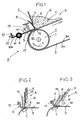
Ausführungsformen des Erfindungsgegenstandes werden anhand der Zeichnungen erläutert. Es zeigen:
- Fig. 1
- eine Seitenansicht eines Teils einer Bandfördervorrichtung mit einer Abdichtvorrichtung, teilweise im Schnitt,
- Fig. 2
- eine andere Ausführungsform einer Abdichtvorrichtung, und
- Fig. 3
- eine andere Ausführungsform einer Abdichtvorrichtung.
- Fig. 1
- a side view of a portion of a belt conveyor device with a sealing device, partially in section,
- Fig. 2
- another embodiment of a sealing device, and
- Fig. 3
- another embodiment of a sealing device.
Eine in Fig. 1 gezeigte Bandfördervorrichtung B ist beispielsweise Teil einer Steig- oder Flachfördervorrichtung in einem Straßenfertiger oder Beschicker, um Fördergut G beispielsweise aus einem nicht gezeigten Bunker (Aufgabebereich) zu einem Abgabebereich zu fördern. Die Bandfördervorrichtung B ist mit einer Abdichtvorrichtung A ausgestattet, die verhindern soll, dass das Fördergut G im Betrieb und/oder bei Stillstand der Bandfördervorrichtung unkontrolliert entgegengesetzt zur Förderrichtung austritt.A belt conveyor B shown in FIG. 1 is, for example, part of a climbing or flat conveying device in a paver or feeder to convey conveyed material G, for example, from a bunker (feed area), not shown, to a delivery area. The belt conveyor B is equipped with a sealing device A, which is intended to prevent the conveyed material G from leaking uncontrollably opposite to the conveying direction during operation and / or at standstill of the belt conveyor device.
Das Fördergut G enthält feste Bestandteile C und ist beispielsweise ein bituminöses oder ein Beton-Einbaugut zum Herstellen von Verkehrsflächen. Solches Fördergut G ist fließfähig und neigt zum Anhaften. Die Bestandteile C können beispielsweise feste Körner in unterschiedlichen Komgrößen sein.The conveyed material G contains solid constituents C and is, for example, a bituminous or a concrete building material for producing traffic areas. Such conveyed material G is free-flowing and tends to adhere. The constituents C may, for example, be solid grains in different grain sizes.
Von der Bandfördervorrichtung B ist ein gurtfördernder Teil 1 erkennbar, hier eine Umlenkrolle 2, um die ein Gurt 3 mit seiner inneren Gurtoberfläche 3b und in festgelegter Zuordnung zur Abdichtvorrichtung A geführt wird. Auf der äußeren Gurtoberfläche 3a wird das Fördergut G in Richtung des Pfeiles 4 gefördert.From the belt conveyor B a belt-conveying part 1 can be seen here a
Die Abdichtvorrichtung A weist eine quer zur Gurtlaufrichtung angeordnete Barriere 5 auf, beispielsweise eine Blech- oder Gummiwand, deren unterer, beispielsweise im Wesentlichen zur Gurtoberseite 3a paralleler oder mit beliebiger Geometrie verlaufender Unterrand 7 in einem deutlichen Abstand von der Gurtoberseite 3 angeordnet ist und mit dieser eine Durchtrittsöffnung 6 begrenzt. Die Weite der Durchtrittsöffnung 6 ist zweckmäßig größer als die größte Bestandteilgröße. Die Durchtrittsöffnung 6 kann so lang sein wie die Gurtbreite, oder kürzer bzw. länger.The sealing device A has a transverse to the direction of
Die Barriere 5 begrenzt an ihrer in Fig. 1 rechten Seite einen Stauraum für das Fördergut G. Auf der dem Stauraum abgewandten Seite der Durchtrittsöffnung 6 ist ein Sperrelement S vorgesehen, das bei der gezeigten Ausführungsform in Fig. 1 eine einstückige schwenkbare Klappe mit einem bogenförmig gekrümmten Sperrschenkel 9, einem Schwenkteil 10 und einer Schwenkteil-Verlängerung 10a ist. Das Sperrelement S ist in einem stationären Schwenklager 11 um eine in etwa zur Achse der Umlenkrolle 2 parallele Schwenkachse 8 gegen die Last einer Feder 14 (und/oder eines Ballasts) aus der gezeigten Lage von der Gurtoberseite 3a weg auslenkbar. Der Sperrschenkel 9 ist breiter als die Weite der Durchtrittsöffnung 7. Der Sperrschenkel 9 streift mit seiner Vorderseite 15 am Unterrand 7 oder ist diesem mit engem Abstand zugeordnet. Am Schwenkteil 10, hier der Schwenkteil-Verlängerung 10a, greift ein stationärer Anschlag 12 an, der die in Fig. 1 gezeigte Abdichtposition des Sperrelements S festlegt. Eine Verstellschraube 13 ermöglicht die Verstellung des Anschlags 12. Der Schwenkteil 10 bildet mit seiner Unterseite eine Anlauffläche 18. Der Sperrschenkel 9 endet unten in einem Abstreifrand 16, der zumindest in etwa parallel zur Gurtoberseite 3a verläuft und mit der Gurtoberseite 3a einen engen Dichtspalt 17 begrenzt. Gegebenenfalls berührt der Abstreifrand 16 sogar die Gurtoberseite 3a, je nach Einstellung des Anschlags 12. Gegebenenfalls weist das Sperrelement S mehrere nebeneinanderliegende, auch einzeln auslenkbare Segmente auf.The
In der gezeigten Betriebsstellung wird bei laufender oder stillstehender Bandfördervorrichtung B durch den Dichtspalt 17 und den Dichtbereich zwischen dem Sperrschenkel 9 und dem Unterrand 7 das Austreten des Förderguts G entgegengesetzt zur Gurtlaufrichtung verhindert. Läuft eine Gurtverdickung um die Umlenkrolle 2, so wird das Sperrelement S oder wenigstens ein Segment gegen die Kraft der Feder 14 ausgelenkt. Fördergut G kann dennoch nicht austreten. Haftet an der Gurtoberseite 3a ein fremder Gegenstand oder ein fester Bestandteil C aus dem Fördergut G, so läuft dieser um die Umlenkrolle 2 gegen die Anlauffläche 18, wodurch das Sperrelement S oder ein Segment vorübergehend ausgelenkt wird und diesen Fremdkörper passieren lässt, ehe das Sperrelement S bzw. das Segment unter der Kraft der Feder 14 sofort wieder in die gezeigte Betriebsstellung zurückkehrt. Sollte an der inneren Bandoberfläche 3b ein Fremdkörper oder ein fester Bestandteil C haften, der zwischen dem Gurt 3 und der Umlenkrolle 2 durchbewegt wird, dann hebt der sich lokal ausbeulende Gurt 3 das Sperrelement S oder ein Segment vorübergehend an, das nach Passieren des Gegenstandes wieder in die gezeigte Lage zurückkehrt. Auf diese Weise wird einerseits verhindert, dass Fördergut G unkontrolliert entgegengesetzt zur Gurtlaufrichtung austreten kann, und andererseits, dass der Gurt oder die Abdichtvorrichtung beschädigt werden.In the operating position shown is running or stationary belt conveyor B through the sealing
Das Sperrelement S oder zumindest der Sperrschenkel 9 kann ein Blech- oder Kunststoffformteil sein oder aus mehreren Formteilen (Segmenten) bestehen.The blocking element S or at least the locking
Bei der Ausführungsform der Abdichtvorrichtung A in Fig. 2 wird das Sperrelement S in etwa parallel zur Barriere 5 verschiebbar geführt. Zwischen dem Sperrschenkel 9 des Sperrelements S und der Barriere 5 kann eine Gummiplatte 19 vorgesehen sein, die in die Durchtrittsöffnung 6 vorsteht und vom Staudruck des Förderguts G gegen den Sperrschenkel 9 angepresst wird. Für das Sperrelement S sind in Fig. 2 nicht gezeigte Führungseinrichtungen vorgesehen. Der Querschnitt des Sperrelementes S ist hier beispielsweise J-förmig. Auch dieses Sperrelement S könnte aus einzeln verschieb- und rückstellbaren Segmenten bestehen.In the embodiment of the sealing device A in FIG. 2, the blocking element S is displaceably guided approximately parallel to the
In den Fig. 1 und 2 sind die Barriere 5 und der Sperrschenkel 9 im Wesentlichen senkrecht zur Gurtoberfläche 3a ausgerichtet.In Figs. 1 and 2, the
Bei der Ausführungsform in Fig. 3 sind die Barriere 5 und der Sperrschenkel 9 schräggestellt, derart, dass die Verschiebebewegung des Sperrelements S (oder des jeweiligen Segments) mit einer Bewegungskomponente in Gurtlaufrichtung erfolgt, was das Auslenken und gegebenenfalls auch das Rückstellen des Sperrelements S unter der Kraft der Feder 14 erleichtert.In the embodiment in Fig. 3, the
Zweckmäßig formt das Sperrelement S (Anlauffläche 18) mit der Gurtoberfläche 3a einen keilförmigen Einlaufspalt. Die Lagerung und der Anschlag für das Sperrelement könnten auch an der Barriere 5 angebracht sein. Der Sperrschenkel 9 könnte sich auch auf der anderen Seite der Barriere 5 befinden.The blocking element S (contact surface 18) expediently forms a wedge-shaped inlet gap with the
Claims (15)
- Belt conveyor device (B), particularly for free-flow material to be conveyed (G) with solid components (C), with a sealing device (A) in which a stationary build-up barrier (5) for the material to be conveyed arranged transversely to the belt running direction (4) is provided with a lower edge (7) spaced apart from a belt surface (3a), and with a sealing gap (17) which runs transversely to the belt running direction and abuts the belt surface (3a) facing away from a belt-guiding part (1), characterised in that a passage opening (6) is provided between the barrier (5) and the belt surface (3a) and in that the passage opening (6) is closed by a locking element (S) which can be displaced in a deflection direction relative to the barrier (5) and its lower edge (7), wherein the locking element (S) forms the actual sealing gap (17) with the belt surface (3a) and can be deflected away from the belt surface (3a) and is loaded against the deflection direction.
- Belt conveyor device according to claim 1, characterised in that the passage opening (6) goes across the breadth of the belt.
- Belt conveyor device according to claim 1, characterised in that the locking element (S) consists of a plurality of segments lying side by side, possibly movable relative to each other.
- Belt conveyor device according to claim 1, characterised in that the locking element (S) is checked against the deflection direction on a, preferably adjustable, stop (12) which defines the width of the sealing gap (17).
- Belt conveyor device according to claim 1, characterised in that the width of the sealing gap is oriented to the size of the solid components (C) of the material to be conveyed (G), preferably being smaller than the smallest component size.
- Belt conveyor device according to claim 1, characterised in that the barrier (5) is a cross wall, preferably made of sheet metal, rubber or elastomer, with a lower edge (7) and the locking element (S) is a flap mounted so as to be pivotable or displaceable with a locking arm (9) arranged adjacent to the lower edge (7).
- Belt conveyor device according to claim 6, characterised in that the lower edge (7) is at least approximately parallel to the belt surface (3a).
- Belt conveyor device according to claim 6, characterised in that the locking arm (9) is arranged on the side of the passage opening (6) facing away from a conveyed material build-up area of the barrier (5).
- Belt conveyor device according to claim 6, characterised in that the locking arm (9) is higher than the width of the passage opening (6).
- Belt conveyor device according to claim 6, characterised in that the locking arm (9) comprises a lower stripping edge (16) at least substantially parallel to the belt surface (3a).
- Belt conveyor device according to claim 6, characterised in that the locking arm (9) is disposed on a pivoting part (10) which is mounted in a pivot bearing (11) with a pivot axis at least approximately parallel to the belt surface (3a) and at a distance from the barrier (5) and in that the stop (12) is preferably aligned with the pivoting part (10) or an extension (10a) of the pivoting part (10).
- Belt conveyor device according to claim 6, characterised in that the locking arm (9) comprises facing the lower edge (7) an arcuate curve with a curve centre lying approximately in the pivot axis of the pivot bearing (11).
- Belt conveyor device according to claim 1, characterised in that the locking element (S) is loaded against the stop (12) by a ballast and / or a spring arrangement (14).
- Belt conveyor device according to claim 6, characterised in that at least the locking arm (9) of the locking element (S) is a sheet metal or plastic moulded component.
- Belt conveyor device according to claim 11, characterised in that the pivoting part (10) forms a running area (18) which preferably defines a wedge-shaped inlet gap with the belt surface (3a).
Applications Claiming Priority (2)
| Application Number | Priority Date | Filing Date | Title |
|---|---|---|---|
| DE20311348U | 2003-07-23 | ||
| DE20311348U DE20311348U1 (en) | 2003-07-23 | 2003-07-23 | Belt conveyor |
Publications (2)
| Publication Number | Publication Date |
|---|---|
| EP1500615A1 EP1500615A1 (en) | 2005-01-26 |
| EP1500615B1 true EP1500615B1 (en) | 2006-05-24 |
Family
ID=33483207
Family Applications (1)
| Application Number | Title | Priority Date | Filing Date |
|---|---|---|---|
| EP04006397A Expired - Lifetime EP1500615B1 (en) | 2003-07-23 | 2004-03-17 | Belt conveyor device with a sealing device |
Country Status (2)
| Country | Link |
|---|---|
| EP (1) | EP1500615B1 (en) |
| DE (2) | DE20311348U1 (en) |
Family Cites Families (3)
| Publication number | Priority date | Publication date | Assignee | Title |
|---|---|---|---|---|
| US4874082A (en) * | 1988-10-14 | 1989-10-17 | Martin Engineering Company | Conveyor skirt board, clamp and mounting arrangement |
| DE29805219U1 (en) * | 1998-03-23 | 1998-08-20 | Olberts GmbH, 47809 Krefeld | Belt conveyor |
| DE29919242U1 (en) * | 1999-11-02 | 2000-02-24 | Joseph Voegele Ag, 68163 Mannheim | Belt conveyors and feeders |
-
2003
- 2003-07-23 DE DE20311348U patent/DE20311348U1/en not_active Expired - Lifetime
-
2004
- 2004-03-17 EP EP04006397A patent/EP1500615B1/en not_active Expired - Lifetime
- 2004-03-17 DE DE502004000610T patent/DE502004000610D1/en not_active Expired - Lifetime
Also Published As
| Publication number | Publication date |
|---|---|
| DE20311348U1 (en) | 2004-12-02 |
| DE502004000610D1 (en) | 2006-06-29 |
| EP1500615A1 (en) | 2005-01-26 |
Similar Documents
| Publication | Publication Date | Title |
|---|---|---|
| EP2664562B1 (en) | Transport device, actuator and traction device for transporting bulk goods | |
| DE19914386C2 (en) | General cargo (continuous) conveyor | |
| DE102008057901A1 (en) | carrier | |
| EP2060512B1 (en) | Facility for conveying goods | |
| DE69100645T2 (en) | Sealing strip for the side walls of a belt conveyor. | |
| DE3438231A1 (en) | PLATE TAPE CONVEYOR | |
| DE3931439C2 (en) | ||
| DE19901287A1 (en) | Bulk solid conveyer belt for use on steep inclines spreads load under varying load conditions using cover belt held down by alternating outer and inner pairs of smaller rollers mounted on swivel arms | |
| AT408748B (en) | loader | |
| EP0256028A1 (en) | Installation for storing and feeding hardware in the correct position. | |
| DE20117346U1 (en) | Loader wagon with unloading device | |
| DE2631643A1 (en) | Conveyor for vertical transport of bulk goods - with enclosed conveying space formed by outer belt and inner belt with undulating edges | |
| DE102018123713B4 (en) | Unloading device for a mixer wagon with actively controlled locking device | |
| DE102015214869A1 (en) | Conveying device for transporting and metering feed parts | |
| EP0088774B1 (en) | Steep gradient or vertical belt conveyor | |
| EP1500615A1 (en) | Belt conveyor device with a sealing device | |
| EP3013716B1 (en) | Sealing device for a conveyor transfer | |
| DE102010015591B3 (en) | metering | |
| DE2037371B2 (en) | Vertical vibratory conveyor for conveying lumpy or granular material | |
| DE202016005250U1 (en) | Trough conveyor for conveying a good | |
| DE3008676A1 (en) | BELT CONVEYOR | |
| DE4040438A1 (en) | Belt conveyor for moving loose material substantially vertical | |
| DE69321727T2 (en) | ARRANGEMENT FOR A CONVEYOR | |
| DE3641809C2 (en) | ||
| DE69800121T2 (en) | Bucket conveyor |
Legal Events
| Date | Code | Title | Description |
|---|---|---|---|
| PUAI | Public reference made under article 153(3) epc to a published international application that has entered the european phase |
Free format text: ORIGINAL CODE: 0009012 |
|
| AK | Designated contracting states |
Kind code of ref document: A1 Designated state(s): AT BE BG CH CY CZ DE DK EE ES FI FR GB GR HU IE IT LI LU MC NL PL PT RO SE SI SK TR |
|
| AX | Request for extension of the european patent |
Extension state: AL LT LV MK |
|
| 17P | Request for examination filed |
Effective date: 20050223 |
|
| AKX | Designation fees paid |
Designated state(s): DE FR IT |
|
| GRAP | Despatch of communication of intention to grant a patent |
Free format text: ORIGINAL CODE: EPIDOSNIGR1 |
|
| GRAS | Grant fee paid |
Free format text: ORIGINAL CODE: EPIDOSNIGR3 |
|
| GRAA | (expected) grant |
Free format text: ORIGINAL CODE: 0009210 |
|
| AK | Designated contracting states |
Kind code of ref document: B1 Designated state(s): DE FR IT |
|
| PG25 | Lapsed in a contracting state [announced via postgrant information from national office to epo] |
Ref country code: IT Free format text: LAPSE BECAUSE OF FAILURE TO SUBMIT A TRANSLATION OF THE DESCRIPTION OR TO PAY THE FEE WITHIN THE PRESCRIBED TIME-LIMIT;WARNING: LAPSES OF ITALIAN PATENTS WITH EFFECTIVE DATE BEFORE 2007 MAY HAVE OCCURRED AT ANY TIME BEFORE 2007. THE CORRECT EFFECTIVE DATE MAY BE DIFFERENT FROM THE ONE RECORDED. Effective date: 20060524 |
|
| REF | Corresponds to: |
Ref document number: 502004000610 Country of ref document: DE Date of ref document: 20060629 Kind code of ref document: P |
|
| ET | Fr: translation filed | ||
| PLBE | No opposition filed within time limit |
Free format text: ORIGINAL CODE: 0009261 |
|
| STAA | Information on the status of an ep patent application or granted ep patent |
Free format text: STATUS: NO OPPOSITION FILED WITHIN TIME LIMIT |
|
| 26N | No opposition filed |
Effective date: 20070227 |
|
| REG | Reference to a national code |
Ref country code: FR Ref legal event code: CA |
|
| REG | Reference to a national code |
Ref country code: FR Ref legal event code: CA Effective date: 20111130 |
|
| REG | Reference to a national code |
Ref country code: DE Ref legal event code: R082 Ref document number: 502004000610 Country of ref document: DE Representative=s name: GRUENECKER, KINKELDEY, STOCKMAIR & SCHWANHAEUS, DE |
|
| REG | Reference to a national code |
Ref country code: DE Ref legal event code: R081 Ref document number: 502004000610 Country of ref document: DE Owner name: JOSEPH VOEGELE AG, DE Free format text: FORMER OWNER: JOSEPH VOEGELE AG, 68163 MANNHEIM, DE Effective date: 20120217 Ref country code: DE Ref legal event code: R082 Ref document number: 502004000610 Country of ref document: DE Representative=s name: GRUENECKER, KINKELDEY, STOCKMAIR & SCHWANHAEUS, DE Effective date: 20120217 Ref country code: DE Ref legal event code: R082 Ref document number: 502004000610 Country of ref document: DE Representative=s name: GRUENECKER PATENT- UND RECHTSANWAELTE PARTG MB, DE Effective date: 20120217 |
|
| REG | Reference to a national code |
Ref country code: FR Ref legal event code: PLFP Year of fee payment: 13 |
|
| REG | Reference to a national code |
Ref country code: FR Ref legal event code: PLFP Year of fee payment: 14 |
|
| REG | Reference to a national code |
Ref country code: FR Ref legal event code: PLFP Year of fee payment: 15 |
|
| PGFP | Annual fee paid to national office [announced via postgrant information from national office to epo] |
Ref country code: FR Payment date: 20230322 Year of fee payment: 20 |
|
| PGFP | Annual fee paid to national office [announced via postgrant information from national office to epo] |
Ref country code: DE Payment date: 20230323 Year of fee payment: 20 |
|
| PGFP | Annual fee paid to national office [announced via postgrant information from national office to epo] |
Ref country code: IT Payment date: 20230331 Year of fee payment: 20 |
|
| REG | Reference to a national code |
Ref country code: DE Ref legal event code: R071 Ref document number: 502004000610 Country of ref document: DE |