EP1500568A2 - Chariot manuel - Google Patents
Chariot manuel Download PDFInfo
- Publication number
- EP1500568A2 EP1500568A2 EP20040016956 EP04016956A EP1500568A2 EP 1500568 A2 EP1500568 A2 EP 1500568A2 EP 20040016956 EP20040016956 EP 20040016956 EP 04016956 A EP04016956 A EP 04016956A EP 1500568 A2 EP1500568 A2 EP 1500568A2
- Authority
- EP
- European Patent Office
- Prior art keywords
- hand truck
- truck according
- frame
- claw
- fingers
- Prior art date
- Legal status (The legal status is an assumption and is not a legal conclusion. Google has not performed a legal analysis and makes no representation as to the accuracy of the status listed.)
- Withdrawn
Links
- 210000000078 claw Anatomy 0.000 claims abstract description 54
- 230000000295 complement effect Effects 0.000 claims description 2
- 238000006073 displacement reaction Methods 0.000 claims description 2
- 241000196324 Embryophyta Species 0.000 description 11
- 230000032258 transport Effects 0.000 description 7
- 230000004048 modification Effects 0.000 description 5
- 238000012986 modification Methods 0.000 description 5
- 238000013461 design Methods 0.000 description 4
- 230000008901 benefit Effects 0.000 description 3
- 238000003780 insertion Methods 0.000 description 3
- 230000037431 insertion Effects 0.000 description 3
- 239000005060 rubber Substances 0.000 description 3
- 238000003466 welding Methods 0.000 description 3
- 235000003332 Ilex aquifolium Nutrition 0.000 description 2
- 241000209027 Ilex aquifolium Species 0.000 description 2
- 239000011324 bead Substances 0.000 description 2
- 238000005520 cutting process Methods 0.000 description 2
- 238000011161 development Methods 0.000 description 2
- 210000000245 forearm Anatomy 0.000 description 2
- 239000000463 material Substances 0.000 description 2
- 239000002184 metal Substances 0.000 description 2
- 230000003716 rejuvenation Effects 0.000 description 2
- 230000000284 resting effect Effects 0.000 description 2
- 238000003892 spreading Methods 0.000 description 2
- 238000003860 storage Methods 0.000 description 2
- 229910000831 Steel Inorganic materials 0.000 description 1
- 238000005452 bending Methods 0.000 description 1
- 230000008859 change Effects 0.000 description 1
- 230000000694 effects Effects 0.000 description 1
- 229920002457 flexible plastic Polymers 0.000 description 1
- 239000003621 irrigation water Substances 0.000 description 1
- 238000004519 manufacturing process Methods 0.000 description 1
- 238000005259 measurement Methods 0.000 description 1
- 238000000465 moulding Methods 0.000 description 1
- 238000004080 punching Methods 0.000 description 1
- 230000007480 spreading Effects 0.000 description 1
- 239000010959 steel Substances 0.000 description 1
Images


Classifications
-
- B—PERFORMING OPERATIONS; TRANSPORTING
- B62—LAND VEHICLES FOR TRAVELLING OTHERWISE THAN ON RAILS
- B62B—HAND-PROPELLED VEHICLES, e.g. HAND CARTS OR PERAMBULATORS; SLEDGES
- B62B1/00—Hand carts having only one axis carrying one or more transport wheels; Equipment therefor
- B62B1/10—Hand carts having only one axis carrying one or more transport wheels; Equipment therefor in which the load is intended to be transferred totally to the wheels
- B62B1/12—Hand carts having only one axis carrying one or more transport wheels; Equipment therefor in which the load is intended to be transferred totally to the wheels involving parts being adjustable, collapsible, attachable, detachable, or convertible
- B62B1/125—Hand carts having only one axis carrying one or more transport wheels; Equipment therefor in which the load is intended to be transferred totally to the wheels involving parts being adjustable, collapsible, attachable, detachable, or convertible by means of telescoping elements
-
- B—PERFORMING OPERATIONS; TRANSPORTING
- B62—LAND VEHICLES FOR TRAVELLING OTHERWISE THAN ON RAILS
- B62B—HAND-PROPELLED VEHICLES, e.g. HAND CARTS OR PERAMBULATORS; SLEDGES
- B62B2202/00—Indexing codes relating to type or characteristics of transported articles
- B62B2202/70—Flowers; Pots; Plants
-
- B—PERFORMING OPERATIONS; TRANSPORTING
- B62—LAND VEHICLES FOR TRAVELLING OTHERWISE THAN ON RAILS
- B62B—HAND-PROPELLED VEHICLES, e.g. HAND CARTS OR PERAMBULATORS; SLEDGES
- B62B2203/00—Grasping, holding, supporting the objects
- B62B2203/44—Clamping or supporting circumferentially
Definitions
- the present invention relates to a uniaxial Hand truck for carrying loads, in particular loads in open containers, in particular of Plants in open pots, as well as an accessory for such a truck.
- Single-axle handcart for carrying loads are in many forms and adapted to various types known by different loads. They have generally an elongated, more or less upright frame on which in a lower Area a wheel axle and in an upper area at least one handle is attached.
- the well-known Sack trucks also have lower ones Completion of the frame a plate-shaped load bearing, put on a sack to be transported, leaning against the frame and then through Tipping the cart can be lifted and transported can.
- For handcart for the transport of compressed gas cylinders can load the load on a small hook be reduced, who in a foot ring one too engages the advancing gas cylinder and this so prevents slippage during transport on the frame.
- To secure the compressed gas cylinder when lifting and during transportation may be at an upper area the frame may be attached to a chain around the to be transported bottle is looped.
- stacking carts as from DE-GM 79 14 058 known, for example, for the carriage of stacked crates are provided is the Load bearing by hooks which can be height-adjusted on the frame replaced, which are intended to be in a handle opening a lower box of a stack introduced to be behind an upper handle bar this Opening to intervene and tilting the cart bottom box with all boxes stacked on top to raise.
- the object of the invention is to provide a handcart, which is good for carrying wide open Containers of squat proportions, in particular of planters with or without plants suitable.
- the task is solved by a handcart with the features of claim 1.
- the movable claw can according to the invention with its at least one free end in the top opening of the too be introduced to the transporting open container, causing them to tilt down the container prevented by the load bearing of the cart forward, even if the load rest does not lower the container his focus.
- Which obliquely forward and sideways extending arms secure the container against tipping in lateral direction.
- the load bearing can therefore kept small, which on the one hand the space requirement keeps the cart low and the other easy makes the load bearing as far as necessary to place under the load to be picked up, so that the claw can engage in the opening and the load can thus be lifted.
- the claw is for this purpose in the Slidably guided longitudinally of the frame. So It is also easy to reach different heights adaptable to transporting container.
- the displaceability is easily realizable via a slidable on the frame sleeve with which the Claw is connected.
- the frame is in an area above the wheel axle formed by a single spar.
- This not only makes the invention Handcart easy and inexpensive to manufacture, but moreover has the advantage that such an individual Spar, if a container plant with spreading To carry a crown is, in general, without difficulty can be pushed into the crown, without damaging them until the spar is in contact with the bucket of the plant passes and the claw in the bucket can be inserted.
- the spar and the sleeve complementary In order to prevent a twisting of the claw against the spar, can the spar and the sleeve complementary, have non-circular cross sections, for example in Shape of oval or rectangular profiles.
- the claw two fingers each having one of the load bearing facing make free end. These two fingers form along with a single spar of the frame one stable fixation, the one loaded on the cart Touched container at three points, thus preventing that the container when using the cart is raised and may be slightly sloping stands, sideways past the spar and of the Cart falls.
- the distance of the fingers from each other, more precisely the distance between the containers touching one Points of the two fingers is preferably between 10 and 20 cm.
- the distance the fingers from each other across the direction of displacement the claw be made changeable.
- This can the claw z. B. provided with a lockable joint be.
- Another option is the two Fingers tapering towards the free ends form so that the depth to which the Fingers can be inserted into a bucket of whose diameter depends.
- the arms are angled and each related to the parallel to the wheel axis one direction from the frame outward-facing section and one at it subsequent inward section in which case the fingers are in contact with each other facing ends of the inward facing Sections can be arranged.
- the distance of Finger of each other is low in this case, the Fingers can even touch one another or become one single finger connected, z. B. welded, be; but there is a safeguard of one to be transported Bucket against a lateral tilting of the cart already alone by the fact that outboard areas of the arms on the top edge of the bucket.
- the at least one is Handle the cart with the cart standing approximately in Waist height of an average sized user, so that this by slightly pushing down the Handle, with substantially downwardly extended Poor, a bucket loaded on the cart can lift and move.
- the frame between the axis and make the handle telescopically extendable allowing a user to change the handle respectively to a height adapted to his body measurements can adjust.
- the pullout can also serve the frame to disassemble in two, leaving the cart stored in a particularly space-saving manner when not in use can be.
- This same purpose may be served by a hinge, that in the frame between axle and handle is inserted.
- Another object of the invention is a handcart specify the type specified, the an easily realizable yet robust Structure has.
- This task is solved by a hand cart with the features of claim 18.
- this safety bar serves at the same time to stiffen the connection between Wheel axle and frame, thus e.g. as one simple welded joint of intersecting pipes can be trained.
- the third point at which the Circlip is attached to the frame higher than the wheel axle, so the distance between this third point and the two attachment points to make the wheel axle big, so that a correspondingly large the connection between the wheel axle and frame loading bending moment by the safety bar can be intercepted.
- the vertical distance between free ends of the securing bracket on the one hand and the load bearing of the Handcart on the other hand is preferably sized that a bucket coaster between these free ends and the load support can be clamped. So the bucket coaster supports one on it even if it is not itself is fully supported by the load support.
- a handcart can drop the load against falling down described above further with a tension belt equipped for laying around a load to be carried be.
- the cart shown in Figure 1 in side view has a frame in the form of a single elongated Holmes 1 made of tubular steel, to which in a lower area a equipped with two wheels 2 axle rod 3, a load support 4 and a securing bracket 5 welded are.
- the load bearing 4 As in particular in the enlarged view of 2, it is the load bearing 4 about a horizontal leg of a roughly L-shaped piece of metal, the upright leg 6 is welded to the spar 1.
- the edge length the substantially rectangular load bearing 4 is a few inches.
- the load bearing 4 has on her facing away from the spar 1 edge 7 a tapered Cross-section that makes it easier to Load support 4 under one standing on the ground to push the load to be picked up without this raise before.
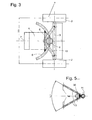
- FIG. 1 shows the cart in a position in which the load support 4 rests flat on the ground.
- this Position is the spar 1 with an angle ⁇ against the vertical inclined.
- This angle ⁇ corresponds in about the typical opening angle of frustoconical walls of typical flower pots or Planters, two of which, designated 8 and 9 respectively, drawn in different sizes in Figure 1 are.
- FIGS. 2 and 3 there are a few Centimeters above the load support 4 on the spar 1 of curved securing bracket 5 through a transverse bore led the Holmes 1 and welded in it.
- the two of the load facing free ends of the securing bracket 5 serve as stops for large Planters and stabilize them during transport in the lateral direction.
- the laterally welded to the spar 1 axle rod 3 is stabilized by a V-shaped carrier 10, the middle region facing one of the load Side of the spar 1 is welded and its ends with the axle rod 3 near whose two ends bearing the wheels are welded.
- a Sleeve 11 slidably disposed along the spar, the one in plan view in approximately V-shaped claw 12 carries.
- a middle region of the claw 12 is on the sleeve 11 facing away from the load at a 8.9 Side welded; from there extend two arms 13 of the claw 12 at an angle of about 60 ° to each other in the direction of the load and run each in a downwardly curved finger 14.
- the depth to which the fingers 14 in one too transportable planters 8, 9 can intervene depends on its diameter and the thickness of one circumferential edge bead of the bucket.
- a screw 36 the extends through a threaded bore of the sleeve, so that they press with their tip against the spar 1 can, or another locking means can provided for fixing the sleeve 11 on the spar 1 become.
- such a locking means but also omitted and the claw 12th only by its own weight and that of the sleeve 11 am Edge of the bucket 8 or 9 held in position.
- FIG. 4A A preferred embodiment of a locking means is shown in Fig. 4A.
- the sleeve 11 surrounds the spar 1 with play, and in a gap between sleeve 11 and spar is a curved Leaf spring 40 inserted under tension, so that they in their middle area against the spar 1 and at its upper and lower ends against the sleeve presses hard enough to prevent the claw from slipping off To prevent spar 1 due to its own weight.
- Another benefit of the spring 40 is that it - If spar 1 and sleeve 11 are round - an unwanted Rotation of the sleeve 11 around the spar 1 prevented.
- the spring 40 is at its upper end to the outside bent over and runs in an outside of the sleeve adjacent Tab 41 off.
- the screw 36 traverses a Bore the tab so that the leaf spring does not can get lost. Moreover, the top presses the Screw in the space against the leaf spring. By adjusting the screw is thus the force with the leaf spring 40 presses against the spar 1, adjustable according to the wishes of a user.
- a development not shown in the drawing According to the claw is 12, more precisely her arms 13, transversely to the spar 1 adjustable in length to the claw to different thicknesses of an upper Adjust the edge bead of a bucket to be transported to be able to.
- a hinge be formed, which is parallel to a wheel axis 3 Axis is pivotable and it allows the fingers of into a bucket at the top.
- a handle 15 at an angled upper end portion 16 of the spar 1 is at a height from about 90 to 110 cm above the ground. This matches with at about the waist of an average User.
- To maneuverability of the cart also contributes with between 10 and 30 cm, preferably about 15 cm right small distance of the wheels 2 from each other.
- the spar is 1 composed of two pipe sections 1a, 1b, the positively interlocked and with each other are connected.
- the lower pipe section 1b a larger cross section and a larger wall thickness as the upper 1a, since it is the entire weight of the bucket from the load support 4 to the axle rod 3, while on the pipe section 1a only the comparatively low pressure and steering forces of the user.
- connection between the two pipe sections 1a, 1b can be permanent, for Example by a weld 37, it may be but also a detachable connection, for example act a screw or locking connection, it allows the two pipe sections 1a, 1b telescopic to move against each other so as to increase the height of the Adjust handle 15, and / or the pipe sections to separate when not in use, so the Store cart space saving.
- For a particularly space-saving storage of the device may also be considered be, in the upper part of the Holmes, in particular in the vicinity of the kink 17 to insert a joint, which allows the spar, on the one hand, in the in Figure 1 to fix position shown, on the other hand, but also the upper end 16 in one parallel to the rest of the spar 1 position swing.
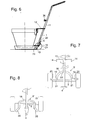
- FIGS. 6 to 9 show a second embodiment the handcart invention.
- the claw 12 and the slidably supporting sleeve 11 are the same as in the first embodiment, so that the views of Figs. 4 and 5 this second embodiment identically transferable are. Differences between the two designs consist in the structure of the chassis, namely are in the second embodiment of the securing bracket 5 and the connection of the axle 3 with the spar 1 stiffening carrier 10 to a securing bracket 5 'merged, which is composed in one piece from a central arch 18 of the, like in Fig. 6, in an approximately vertical plane is arranged two from the ends of the central arch 18 forward, towards one 4 resting planter 8 on the load support extending arms 19 and arc-shaped plant legs 20 extending from the ends of the arms 19 off in a horizontal plane forward and sideways extend to the outside.
- the securing bracket 5 'stiffens the chassis by two welding points 21 between the arms 19 and the axle rod 3 and a third welding point 22, the central arch 18 above the axle rod 3 in the middle with the spar 1 connects.
- the central one Bow 18 is shown here in a semicircle, however, it comes in any other design Consider that a rigid connection between the Welding points 21, 22 guaranteed.
- the distance between the load support 4 and the bottom the arms 19 and bearing leg 20 of the securing bracket 5 ' is the height of a saucer 23 of the planter 8 adapted so that this Coasters 23, when the load support 4 under pushed him, the circlip 5 at the Poor 19 and / or plant legs 20 touched and so on is secure against tipping.
- the load bearing 4 is to her Point pointed like a cake server pointed.
- Fig. 10 shows a further developed embodiment the handcart in a top view. It makes a difference from the reference to Figs. 6 to 9 described through three characteristics that are independent of each other can be realized.
- Fig. 11 shows in a side view analogous to Fig. 9 is a development of the in Figs. 6 to 9 handcart shown.
- a safety belt 24 is around a lower area of one on the cart wrapped bucket 8 and the spar 1, to pull the planter 8 against the spar 1 and so secure.
- the illustrated in Fig. 10 Graphkübel 8 has no saucer, so he to the plant legs 20 of the securing bracket 5 'is applied.
- the safety belt 24 can permanently on the spar 1 or another suitable part of the chassis of the Carriage can be attached and can be so when not in use is not in the way, e.g. over the claw 12 to be hanged.
- the safety belt 24 but removable and as shown in Fig. 12 on Holm 1 against slipping simply by a hook 25 secured from a connected to the spar Root out over several inches in parallel extends to the spar upwards and so a gap 26th forms, in which the safety belt 24 at Use can be hung.
- FIG. 12 A third embodiment of the handcart is shown in FIG. 12 shown in a partial front view. she differs from the embodiment of FIG. 6 to 9 due to the presence of two tension springs 27, here in the form of two rubber cables 28, the on their ends carry hooks 29, one of which the Axle bar 3 and the other one arm of the claw 12th wraps.
- the tension springs 27 exert on the claw 12 a along of the spar 1 downward force, the unintentional escape of the fingers 14 of the Claw 12 from a planter loaded on the cart prevents, even if the sleeve 11 does not like in Fig. 4, by a clamping screw 36 or the like on the spar 1 can be locked.
- the two tension springs 27 of the Fig. 13 also by a single symmetrical on the Claw 12 attacking tension spring to be replaced, for example through a single rubber cord that with Hook on both ends of the claw 12 attacks and is wrapped around the axle 3.
- Such Buchfeder also offered the possibility, they, if a very large bucket needs to be loaded with one end on the claw 12 and with its other End at the axle bar 3 or the central bow 18 hook and so to lift the claw in a height required for insertion into the bucket To keep low force to be exerted against the spring.
- Figs. 14 and 15 show in views analogous to 4 and 5 is a side view and a plan view to an alternative embodiment of a Claw 12 '.
- the sleeve 11 of this claw is identical with that shown in Fig. 4.
- the claw 12 ' Instead of straightforward from the sleeve 11 extending arms 13, as shown in FIG. 5, the claw 12 'has arms 13 ', each one of the sleeve 11th from straight forward and sideways extending "Oberarmab mustard" 30, an adjoining curved "elbow portion” 31 and a from the elbow portion 31 to a vertical one Center plane of the cart extending "forearm section" 32 have.
- FIGS. 16 and 17 Another alternative embodiment of a claw 12 "is shown in FIGS. 16 and 17 in FIGS. 15 analogue representations shown.
- FIG. 20 A first embodiment of an accessory for the Cart according to the invention, which recording of Planting pots or other heavy containers with the handcart described above or another for insertion under a load to be absorbed provided load support is shown in Fig. 20 in a plan view and in Fig. 21 in a Section along the line XXI-XXI shown in FIG. 20.
- the accessory according to this first embodiment is as a separate from the load to be recorded Part trained.
- this accessory it is a one-piece molding made of hard or flexible plastic, rubber or Metal. He has the shape of a star with one Plurality of with a central, ring or ring segment-shaped Core 41 connected and different from this from radially extending, in a uniform Angular distance arranged beams 42.
- the Accessory is intended to be on a floor as a support for a planter or a saucer to be placed in a planter; the strength of its rays 42 corresponds at least the strength of the load support 4 of the handcart, so that the tip of the load bearing 4 in a space 43 or 44 between two beams 42 into one Position can be inserted, in which the top the load support 4 not far from the center 45 is removed or even reached.
- the Planter should be placed on the accessory so be that its vertical central axis through the Center 45 runs. With the help of the accessory it is possible, the load support 4 under a Insert planter without the need for this it has to be tilted, what about the loading of a bucket considerably relieved on the cart.
- the accessory can be a consistent everywhere Have thickness; in this case, the load bearing 4 only so close to the center 45 introduced as the outline of the core 41 allows.
- the thickness of the core 41 is less than the rays 42, and the core touches the ground not, but a space between the core and the underground is high enough to the Insert load pickup 4 therein to center 45 to be able to.
- the thickness of the beams 42 may, for. B. about 10 mm and that of the core amount to half of it.
- Such a deepening Gap also facilitates drainage from excess irrigation water from a central Drain hole of a bucket standing on it.
- Fig. 21 shows are to the Beams 42 at regular intervals weak points 46 shaped.
- the vulnerabilities 46 are on concentric circles around the center 45 and they are destined to receive the rays 42 each according to the diameter of a bucket or coaster with which the accessory is used should be shorten, so that the accessory not sticking out underneath.
- the accessory can be shortened by canceling or cutting, e.g. with scissors or a Side cutter, done.
- the weak points also as rejuvenation in latitudes or circumferential direction, by perforation or the like be trained; they could also go through printed or stamped cutting marks be replaced.
- a second accessory in the form of an inventive Cart fitted coaster is in Fig. 22 partly in section, partly in a side view and Fig. 23 is a bottom view.
- the saucer has a flat bottom 51 and a sidewall 52 surrounding the floor
- Bottom of the bottom are several radially oriented Ridges 53 formed, the height of each at least corresponds to the strength of the load support 4, so that these are in the spaces 54 between the Ribs can be inserted from the outside to the Coaster together with a bucket located on it to raise.
- These ribs point in the radial direction inner endpoints whose distance from each other is large enough to advance the load bearing between the ribs to below the center the bottom plate or at least until its To allow proximity.
Landscapes
- Engineering & Computer Science (AREA)
- Chemical & Material Sciences (AREA)
- Combustion & Propulsion (AREA)
- Transportation (AREA)
- Mechanical Engineering (AREA)
- Handcart (AREA)
Applications Claiming Priority (4)
| Application Number | Priority Date | Filing Date | Title |
|---|---|---|---|
| DE10333449 | 2003-07-22 | ||
| DE2003133449 DE10333449A1 (de) | 2003-07-22 | 2003-07-22 | Handkarre |
| DE20316467U DE20316467U1 (de) | 2003-07-22 | 2003-10-24 | Handkarre |
| DE20316467U | 2003-10-24 |
Publications (1)
| Publication Number | Publication Date |
|---|---|
| EP1500568A2 true EP1500568A2 (fr) | 2005-01-26 |
Family
ID=33491672
Family Applications (1)
| Application Number | Title | Priority Date | Filing Date |
|---|---|---|---|
| EP20040016956 Withdrawn EP1500568A2 (fr) | 2003-07-22 | 2004-07-19 | Chariot manuel |
Country Status (1)
| Country | Link |
|---|---|
| EP (1) | EP1500568A2 (fr) |
Cited By (6)
| Publication number | Priority date | Publication date | Assignee | Title |
|---|---|---|---|---|
| DE202010001115U1 (de) | 2010-01-20 | 2010-06-17 | Medvetskiy, Oleksandr | Der Handzweiradkarren oder der Koffer mit der Einrichtung für die Überwindung der engen und tiefen Hindernisse |
| DE102009052215A1 (de) | 2009-11-06 | 2011-05-12 | Medvetskiy, Oleksandr | Der Handzweiradkarren oder der Koffer mit der Einrichtung für die Überwindung der engen und tiefen Hindernisse |
| ITPD20100257A1 (it) * | 2010-08-09 | 2012-02-10 | Gastaldi Christian | Dispositivo di presa e supporto per vasi di medie e grandi dimensioni, particolarmente per carrelli da vivaismo a due ruote |
| DE202015100187U1 (de) | 2015-01-15 | 2015-02-25 | Jürgen Froß | Vertikal-Hubwagen |
| WO2015051994A1 (fr) | 2013-10-11 | 2015-04-16 | Jürgen Fross | Chariot élévateur vertical |
| EP3045375A1 (fr) | 2015-01-15 | 2016-07-20 | Jürgen Fross | Chariot élévateur vertical |
-
2004
- 2004-07-19 EP EP20040016956 patent/EP1500568A2/fr not_active Withdrawn
Cited By (7)
| Publication number | Priority date | Publication date | Assignee | Title |
|---|---|---|---|---|
| DE102009052215A1 (de) | 2009-11-06 | 2011-05-12 | Medvetskiy, Oleksandr | Der Handzweiradkarren oder der Koffer mit der Einrichtung für die Überwindung der engen und tiefen Hindernisse |
| DE202010001115U1 (de) | 2010-01-20 | 2010-06-17 | Medvetskiy, Oleksandr | Der Handzweiradkarren oder der Koffer mit der Einrichtung für die Überwindung der engen und tiefen Hindernisse |
| ITPD20100257A1 (it) * | 2010-08-09 | 2012-02-10 | Gastaldi Christian | Dispositivo di presa e supporto per vasi di medie e grandi dimensioni, particolarmente per carrelli da vivaismo a due ruote |
| EP2418136A1 (fr) * | 2010-08-09 | 2012-02-15 | Gastaldi, Christian | Dispositif à roues de préhension et de support pour vases |
| WO2015051994A1 (fr) | 2013-10-11 | 2015-04-16 | Jürgen Fross | Chariot élévateur vertical |
| DE202015100187U1 (de) | 2015-01-15 | 2015-02-25 | Jürgen Froß | Vertikal-Hubwagen |
| EP3045375A1 (fr) | 2015-01-15 | 2016-07-20 | Jürgen Fross | Chariot élévateur vertical |
Similar Documents
| Publication | Publication Date | Title |
|---|---|---|
| DE2939003A1 (de) | Gebrauchskarren | |
| EP3431363B1 (fr) | Cadre de transport | |
| WO2011091925A1 (fr) | Chariot à plate-formes, muni d'une plate-forme pouvant basculer vers le haut de deux côtés | |
| EP1500568A2 (fr) | Chariot manuel | |
| DE4133503C2 (de) | Verfahrbares Gerät zum getrennten manuellen Sammeln unterschiedlicher Abfallstoffe, insbesondere recyclingfähiger Abfallstoffe | |
| DE202016100132U1 (de) | Rundballensammelvorrichtung und Rundballensammelfahrzeug mit einer derartigen Rundballensammelvorrichtung | |
| DE9002279U1 (de) | Sackkarrenartige Transportkarre | |
| DE102011000610B4 (de) | Karre zum Transport einer Stapelkiste | |
| EP0055422B1 (fr) | Dispositif pour dérouler et découper une bande de matériau | |
| DE20316467U1 (de) | Handkarre | |
| DE102016104861A1 (de) | Kippschutzvorrichtung | |
| WO2014147227A1 (fr) | Dispositif pour structures portables | |
| DE102008063474B4 (de) | Hand-Rücke-Karre | |
| DE4113254A1 (de) | Handhabungs- und/oder verlegevorrichtung fuer steine | |
| DE202005017507U1 (de) | Einachsiger Handwagen | |
| DE102020108026B3 (de) | Transportvorrichtung für eine Rüttelplatte | |
| EP3741646A1 (fr) | Rouleaux de transport | |
| DE10317864A1 (de) | Vorrichtung zum Zuschneiden von Holzstücken | |
| DE8904428U1 (de) | Stapelbarer Einkaufswagen | |
| DE102014115730A1 (de) | Transportkarre für Fußplatten | |
| DE4134948C2 (de) | Transportwagen, insbesondere für Leerkettbäume | |
| DE20016212U1 (de) | Schubwagen | |
| DE9101895U1 (de) | Angelsportgerätewagen | |
| AT257465B (de) | Holzrückgerät | |
| AT14281U2 (de) | Pflanzentopf - Kübelheber zum Transportieren und Heben von Pflanzentöpfen, Kübeln, Dekosteine, Amphoren |
Legal Events
| Date | Code | Title | Description |
|---|---|---|---|
| PUAI | Public reference made under article 153(3) epc to a published international application that has entered the european phase |
Free format text: ORIGINAL CODE: 0009012 |
|
| AK | Designated contracting states |
Kind code of ref document: A2 Designated state(s): AT BE BG CH CY CZ DE DK EE ES FI FR GB GR HU IE IT LI LU MC NL PL PT RO SE SI SK TR |
|
| AX | Request for extension of the european patent |
Extension state: AL HR LT LV MK |
|
| STAA | Information on the status of an ep patent application or granted ep patent |
Free format text: STATUS: THE APPLICATION IS DEEMED TO BE WITHDRAWN |
|
| 18D | Application deemed to be withdrawn |
Effective date: 20070201 |