EP1500517A1 - Kompakte Anordnung zum Detektieren der unbenutzten Farbbandlänge - Google Patents
Kompakte Anordnung zum Detektieren der unbenutzten Farbbandlänge Download PDFInfo
- Publication number
- EP1500517A1 EP1500517A1 EP04016457A EP04016457A EP1500517A1 EP 1500517 A1 EP1500517 A1 EP 1500517A1 EP 04016457 A EP04016457 A EP 04016457A EP 04016457 A EP04016457 A EP 04016457A EP 1500517 A1 EP1500517 A1 EP 1500517A1
- Authority
- EP
- European Patent Office
- Prior art keywords
- ribbon
- ink ribbon
- core
- amount
- ink
- Prior art date
- Legal status (The legal status is an assumption and is not a legal conclusion. Google has not performed a legal analysis and makes no representation as to the accuracy of the status listed.)
- Granted
Links
- 238000000638 solvent extraction Methods 0.000 claims abstract description 26
- 230000002159 abnormal effect Effects 0.000 description 2
- 238000000034 method Methods 0.000 description 2
- 230000000007 visual effect Effects 0.000 description 2
- 239000000470 constituent Substances 0.000 description 1
- 238000010276 construction Methods 0.000 description 1
- 238000010348 incorporation Methods 0.000 description 1
- 238000004519 manufacturing process Methods 0.000 description 1
- 238000003825 pressing Methods 0.000 description 1
Images


Classifications
-
- B—PERFORMING OPERATIONS; TRANSPORTING
- B41—PRINTING; LINING MACHINES; TYPEWRITERS; STAMPS
- B41J—TYPEWRITERS; SELECTIVE PRINTING MECHANISMS, i.e. MECHANISMS PRINTING OTHERWISE THAN FROM A FORME; CORRECTION OF TYPOGRAPHICAL ERRORS
- B41J17/00—Mechanisms for manipulating page-width impression-transfer material, e.g. carbon paper
- B41J17/36—Alarms, indicators, or feed-disabling devices responsible to material breakage or exhaustion
-
- B—PERFORMING OPERATIONS; TRANSPORTING
- B41—PRINTING; LINING MACHINES; TYPEWRITERS; STAMPS
- B41J—TYPEWRITERS; SELECTIVE PRINTING MECHANISMS, i.e. MECHANISMS PRINTING OTHERWISE THAN FROM A FORME; CORRECTION OF TYPOGRAPHICAL ERRORS
- B41J35/00—Other apparatus or arrangements associated with, or incorporated in, ink-ribbon mechanisms
- B41J35/36—Alarms, indicators, or feed disabling devices responsive to ink ribbon breakage or exhaustion
Definitions
- the present invention relates generally to an image printing apparatus, such as a facsimile machine or a printer, using a rolled ink ribbon. More particularly, the invention is concerned with a compact and low-cost arrangement which can detect the amount of an unused portion of an ink ribbon and whether the ink ribbon is securely mounted in an image printing apparatus.
- FIG. 4 shows a commonly known structure employed in an image printing apparatus, such as a facsimile machine or a printer, using a rolled ink ribbon.
- the structure of FIG. 4 includes a supply spool on which an unused portion of the ink ribbon is wound and a take-up spool on which a used portion of the ink ribbon is wound.
- the image printing apparatus includes a thermal head and a platen roller located in a surrounding area of the ink ribbon for transferring ink from the ink ribbon to printing paper.
- the image printing apparatus is constructed in such a fashion that the platen roller feeds the printing paper while pressing the printing paper and the ink ribbon tight against each other and the take-up spool is turned at a speed matched to printing speed to continuously wind up the used portion of the ink ribbon during a print job.
- a conventional arrangement as disclosed in Japanese Laid-open Patent Application Nos. H04-331178 and 2001-47717 employs an encoder including a disk in which a plurality of slits are formed and a sensor for detecting rotation of a ribbon spool, the disk being disposed outside but on a common axis with the ribbon spool (supply or take-up side).
- This encoder counts the amount of rotation of the ribbon spool, and the amount of the unused portion of the ink ribbon is calculated based on the counted amount of rotation of the ribbon spool.
- FIG. 5 is a schematic sectional view showing a typical structure of the aforementioned conventional arrangement. As shown in FIG.
- a rotating amount detecting device including a disk 13 in which a plurality of slits 3 are formed and a sensor 2 for detecting rotation is installed in an apparatus body 5 which is separate from a ribbon core 4 on which an ink ribbon 1 is wound.
- the aforementioned conventional arrangements employ the rotating amount detecting device (encoder), there is the need for an extra space in an image printing apparatus for installing such components as the disk in which a plurality of slits are formed and the sensor for detecting the slits. Accordingly, the conventional arrangements have a problem that the image printing apparatus becomes unnecessarily large. Another problem of the conventional arrangements is that incorporation of the rotating amount detecting device (encoder) results in an increase in the manufacturing cost of the apparatus because the provision of the aforementioned components increases the number of constituent elements and these components are expensive high-precision parts.
- a ribbon support device for rotatably supporting a rolled ink ribbon includes a partitioning disk mounted in a terminal part of a ribbon core on which the ink ribbon is wound, the partitioning disk having openings or projections used for detecting rotation of the rolled ink ribbon, and a sensor element for detecting the openings or the projections, the sensor element being mounted inside a spool element supporting the ribbon core.
- the sensor element e.g., a photoelectric sensor or a switch
- the spool element detects the openings or the projections formed in the partitioning disk mounted in the terminal part of the ribbon core, it is possible to easily detect rotation of the ink ribbon. Therefore, if provision is made to feed the ink ribbon by means of a stepping motor, for instance, it is possible to easily know the amount of ribbon feed attained by a specific number of rotations (e.g., a single rotation) of the rolled ink ribbon.
- the amount of ribbon feed is known, the current outside diameter of the rolled ink ribbon can be determined. The amount of an unused portion of the ink ribbon can be calculated from the current outside diameter of the rolled ink ribbon thus obtained.
- the ribbon support device of the invention makes it possible to easily determine the amount of the unused portion of the ink ribbon with a simple structure, without the need for separately providing a disk having a plurality of slits formed therein on the outside of the ribbon core.
- the ribbon support device of the invention it is possible to definitely determine the amount of the unused portion of the ink ribbon based on the amount of feed (or the number of steps) of the stepping motor per the aforementioned specific number of rotations of the rolled ink ribbon. Therefore, the ribbon support device of the invention is advantageous in that it is possible to determine the amount of the unused portion of the ink ribbon even when the ink ribbon is once removed from an apparatus body and mounted again.
- a structured ink ribbon unit includes a ribbon core, a rolled ink ribbon wound around the ribbon core, and a partitioning disk mounted in a terminal part of the ribbon core, the partitioning disk having openings or projections used for detecting rotation of the rolled ink ribbon.
- the ribbon support device can not detect the openings or the projections formed in the partitioning disk for detecting rotation of the rolled ink ribbon if the ribbon core is not correctly installed.
- the image printing apparatus can notify a user of an abnormal situation by producing a warning if the ribbon core is not correctly installed.
- FIG. 1 is a sectional view of the ribbon support device and the structured ink ribbon unit
- FIG. 2 is an enlarged sectional view showing part of the ribbon support device.
- the structured ink ribbon unit includes a hollow ribbon core 4 and a rolled ink ribbon 1 which is wound around the ribbon core 4 in a cylindrical form.
- a partitioning disk 6 On the inside of the ribbon core 4, there is mounted a partitioning disk 6 at a specific distance from one end of the ribbon core 4. There are formed a large number of radially arranged narrow openings, or slits, 9 in the partitioning disk 6.
- a ribbon core spool element 11 which fits into a cylindrical hole in the ribbon core 4 and supports the ribbon core 4, the ribbon core spool element 11 incorporating a reflection-type photoelectric sensor 10 for detecting rotation of the partitioning disk 6.
- a detachable ribbon core spool element 8 At the other end of the ribbon core 4 opposite to the ribbon core spool element 11, there is provided a detachable ribbon core spool element 8 as shown in FIG. 1.
- the outside diameter of the ribbon core spool element 11 is made approximately equal to the inside diameter of the ribbon core 4, and the sensor 10 incorporated in the ribbon core spool element 11 is located at a point slightly offset from a geometrical center of the partitioning disk 6. Since the sensor 10 is located between the end of the ribbon core 4 and the partitioning disk 6 on the inside of the ribbon core spool element 11, the provision of this sensor 10 does not cause any increase in the overall size of the ribbon support device. Since a large number of radial slits 9 are formed in the partitioning disk 6 along a rotating direction thereof, each rotation of the ribbon core 4 is detected when the sensor 10 has detected all the slits 9 formed in the partitioning disk 6.
- the number of slits 9 formed in the partitioning disk 6 need not be so large.
- the number of slits 9 formed in the partitioning disk 6 should preferably be made as large as possible to achieve high accuracy.
- FIG. 3 shows the shape of the partitioning disk 6 having the slits 9 as view from one side thereof.
- the sensor 10 verifies whether the ribbon core 4 rotates by detecting the slits 9 formed in the partitioning disk 6 which is mounted in the rotating ribbon core 4. If an output of the sensor 10 alternates between ON and OFF states, the ink ribbon unit currently used is a correct standard product. If the output of the sensor 10 does not alternate between the ON and OFF states, the ink ribbon unit currently used is a wrong, or nonstandard, product or not correctly mounted. In the latter case, the ribbon support device produces an audible or visual warning to alert the user to an abnormal situation. As the sensor 10 counts the number of slits 9, the ribbon support device determines whether the counted number of slits 9 has reached a value corresponding to one rotation of the ribbon core 4, or the rolled ink ribbon 1.
- the partitioning disk 6 may have a number of projections instead of the slits 9.
- the ribbon support device may employ a transmission-type sensor or a switch instead of the aforementioned reflection-type photoelectric sensor 10.
- the ribbon support device it is possible to calculate the length L of the ink ribbon 1 supplied by one rotation of the ink ribbon 1 by counting the amount of feed (or the number of steps) of the ribbon feeding stepping motor per rotation of the ink ribbon 1.
- outside diameter D of the ink ribbon 1 is known, it is possible to calculate the amount of an unused portion (or remainder) LL of the ink ribbon 1 from a commonly known equation for calculating the length of a rolled product.
- the ribbon support device determines the length LL of the remainder of the ink ribbon 1 in the aforementioned manner.
- the ribbon support device notifies the user by producing a buzzer sound or a visual indication.
- the length LL of the remainder of the ink ribbon 1 can be definitely determined based on the amount of feed (or the number of steps) of the ribbon feeding stepping motor per rotation of the ink ribbon 1.
- the aforementioned arrangement of the embodiment is advantageous in that it is possible to determine the length LL of the remainder of the ink ribbon 1 even when the structured ink ribbon unit is once removed from the apparatus body and mounted again.
- the ribbon support device is applicable to a known image printing apparatus for printing an image on paper by use of an ink ribbon.
- a CPU of the image printing apparatus also functioning as a ribbon remainder calculator calculates the amount of the unused portion LL.
- the CPU detects whether the ink ribbon is correctly mounted by detecting the rotation of the openings or the projections.
- the image printing apparatus has an indicator for indicating the amount of the unused portion LL calculated by the CPU, thereby allowing a user to confirm when the ink ribbon should be changed. The indicator gives a warning when the ink ribbon is not correctly mounted.
- the amount of a used portion or an unused portion of the ink ribbon 1 may be determined based on an experimentally obtained relationship between the amount of the used portion or the unused portion of the ink ribbon 1 and the number of feeding steps of the ribbon feeding stepping motor.
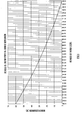
- the experimentally obtained relationship between the amount of the used portion or the unused portion of the ink ribbon 1 and the number of feeding steps of the stepping motor is graphed as shown in FIG. 6, for example.
- the amount of the used portion or the unused portion of the ink ribbon 1 is determined based on the accumulated number of feeding steps of the stepping motor using a graph thus obtained.
- the horizontal axis represents the accumulated number of feeding steps of the stepping motor while the vertical axis represents the length of the remainder of the ink ribbon 1.
- the ribbon support device of the foregoing embodiment is applicable to any kinds of apparatuses as a device for supporting a rolled ink ribbon or rolled printing paper. When applied to such apparatuses, the ribbon support device can detect the amount of an unused portion of the ink ribbon or the printing paper with high accuracy.
- a facsimile machine for example, employs a stepping motor which feeds an ink ribbon at a rate of 1/7.7 mm to 1/15.4 mm per step of the stepping motor. Since this ribbon feeding length per step of the stepping motor is sufficiently small compared to the length of an printable area on each sheet of printing paper, the ribbon support device applied to the facsimile machine can precisely detect the amount of the unused portion of the ink ribbon.
Landscapes
- Impression-Transfer Materials And Handling Thereof (AREA)
- Inking, Control Or Cleaning Of Printing Machines (AREA)
Applications Claiming Priority (2)
| Application Number | Priority Date | Filing Date | Title |
|---|---|---|---|
| JP2003279381 | 2003-07-24 | ||
| JP2003279381A JP2005041163A (ja) | 2003-07-24 | 2003-07-24 | リボン支持構造、インクリボン構造体及び画像印刷装置 |
Publications (2)
| Publication Number | Publication Date |
|---|---|
| EP1500517A1 true EP1500517A1 (de) | 2005-01-26 |
| EP1500517B1 EP1500517B1 (de) | 2006-09-20 |
Family
ID=33487717
Family Applications (1)
| Application Number | Title | Priority Date | Filing Date |
|---|---|---|---|
| EP20040016457 Expired - Lifetime EP1500517B1 (de) | 2003-07-24 | 2004-07-13 | Kompakte Anordnung zum Detektieren der unbenutzten Farbbandlänge |
Country Status (4)
| Country | Link |
|---|---|
| EP (1) | EP1500517B1 (de) |
| JP (1) | JP2005041163A (de) |
| CN (1) | CN1325278C (de) |
| DE (1) | DE602004002434T2 (de) |
Cited By (2)
| Publication number | Priority date | Publication date | Assignee | Title |
|---|---|---|---|---|
| US11148446B2 (en) | 2015-07-31 | 2021-10-19 | Videojet Technologies Inc. | Tape drive and associated spool |
| EP4686573A1 (de) * | 2024-07-31 | 2026-02-04 | Brady Worldwide, Inc. | System und verfahren zur farbbandausrichtung eines druckers |
Families Citing this family (5)
| Publication number | Priority date | Publication date | Assignee | Title |
|---|---|---|---|---|
| JP2007190873A (ja) * | 2006-01-23 | 2007-08-02 | Funai Electric Co Ltd | プリンタ装置 |
| CN103332026B (zh) * | 2013-06-28 | 2015-08-19 | 上海宜达胜电脑用品有限公司 | 一种保护打印机的色带寿命计量装置及色带盒寿命计量方法 |
| JP6346766B2 (ja) * | 2014-03-24 | 2018-06-20 | セイコーエプソン株式会社 | テープカートリッジ |
| CN106881966B (zh) * | 2017-03-06 | 2023-06-09 | 深圳西龙同辉技术股份有限公司 | 一种用于凹码打印的色带机构 |
| JP7429163B2 (ja) * | 2020-06-19 | 2024-02-07 | ローランドディー.ジー.株式会社 | 箔転写ユニット付きインクジェットプリンタ |
Citations (4)
| Publication number | Priority date | Publication date | Assignee | Title |
|---|---|---|---|---|
| JPH04331178A (ja) | 1991-05-02 | 1992-11-19 | Sony Corp | リボンの残量検出方法 |
| JPH0647977A (ja) | 1991-11-21 | 1994-02-22 | Samsung Electronics Co Ltd | カラービデオプリンターのカートリッジリボン残量表示装置 |
| JPH10244724A (ja) | 1997-03-06 | 1998-09-14 | Oki Electric Ind Co Ltd | インクリボン巻取装置と券処理装置 |
| JP2001047717A (ja) | 1999-08-09 | 2001-02-20 | Nippon Totor Co Ltd | インクリボン残量検出装置 |
Family Cites Families (4)
| Publication number | Priority date | Publication date | Assignee | Title |
|---|---|---|---|---|
| US4698567A (en) * | 1985-12-27 | 1987-10-06 | Xerox Corporation | Ribbon deck motor control |
| JP2930523B2 (ja) * | 1994-05-31 | 1999-08-03 | 東芝テック株式会社 | 転写式プリンタ |
| JP2003103816A (ja) * | 2001-10-01 | 2003-04-09 | Toshiba Tec Corp | 熱転写プリンタ |
| JP2003211765A (ja) * | 2001-11-16 | 2003-07-29 | Matsushita Electric Ind Co Ltd | 印字装置及びロール装置 |
-
2003
- 2003-07-24 JP JP2003279381A patent/JP2005041163A/ja active Pending
-
2004
- 2004-07-13 EP EP20040016457 patent/EP1500517B1/de not_active Expired - Lifetime
- 2004-07-13 DE DE602004002434T patent/DE602004002434T2/de not_active Expired - Lifetime
- 2004-07-26 CN CNB2004100549763A patent/CN1325278C/zh not_active Expired - Fee Related
Patent Citations (5)
| Publication number | Priority date | Publication date | Assignee | Title |
|---|---|---|---|---|
| JPH04331178A (ja) | 1991-05-02 | 1992-11-19 | Sony Corp | リボンの残量検出方法 |
| JPH0647977A (ja) | 1991-11-21 | 1994-02-22 | Samsung Electronics Co Ltd | カラービデオプリンターのカートリッジリボン残量表示装置 |
| US5333960A (en) * | 1991-11-21 | 1994-08-02 | Samsung Electronics Co., Ltd. | Device and method for displaying a residual amount of cartridge ribbon for a color video printer |
| JPH10244724A (ja) | 1997-03-06 | 1998-09-14 | Oki Electric Ind Co Ltd | インクリボン巻取装置と券処理装置 |
| JP2001047717A (ja) | 1999-08-09 | 2001-02-20 | Nippon Totor Co Ltd | インクリボン残量検出装置 |
Non-Patent Citations (1)
| Title |
|---|
| PATENT ABSTRACTS OF JAPAN vol. 2000, no. 19 5 June 2001 (2001-06-05) * |
Cited By (2)
| Publication number | Priority date | Publication date | Assignee | Title |
|---|---|---|---|---|
| US11148446B2 (en) | 2015-07-31 | 2021-10-19 | Videojet Technologies Inc. | Tape drive and associated spool |
| EP4686573A1 (de) * | 2024-07-31 | 2026-02-04 | Brady Worldwide, Inc. | System und verfahren zur farbbandausrichtung eines druckers |
Also Published As
| Publication number | Publication date |
|---|---|
| DE602004002434D1 (de) | 2006-11-02 |
| EP1500517B1 (de) | 2006-09-20 |
| CN1325278C (zh) | 2007-07-11 |
| JP2005041163A (ja) | 2005-02-17 |
| CN1576043A (zh) | 2005-02-09 |
| DE602004002434T2 (de) | 2007-04-26 |
Similar Documents
| Publication | Publication Date | Title |
|---|---|---|
| EP3088193B1 (de) | Mediumaufwicklungsvorrichtung | |
| EP1500517B1 (de) | Kompakte Anordnung zum Detektieren der unbenutzten Farbbandlänge | |
| JP2749490B2 (ja) | カラービデオプリンターのカートリッジリボン残量表示装置 | |
| EP0401036B1 (de) | Druckmaschine für Thermodruck-Rollenpapier | |
| EP0852182B1 (de) | Farbbandkassette | |
| USRE42088E1 (en) | Printer | |
| WO2006120870A1 (ja) | プリンタ | |
| EP0121971A1 (de) | Antriebsvorrichtung für Bandkassette | |
| JP3789950B2 (ja) | 給紙制御装置 | |
| JP5882115B2 (ja) | 管理用装置及びこれを用いた管理システム | |
| KR20110009068A (ko) | 잉크리본 잼판정방법 | |
| US20060157526A1 (en) | Paper feeding apparatus | |
| JPH07101601A (ja) | ロール紙保持装置 | |
| JP6546514B2 (ja) | プリンタ | |
| JP7567327B2 (ja) | 印刷用カセット、印刷装置及び印刷装置本体 | |
| JP2007030430A (ja) | プリンターのリボンエンド検出装置 | |
| JPS63246274A (ja) | プリンタ | |
| JP7196564B2 (ja) | 巻取り装置および印刷装置 | |
| JP2001047717A (ja) | インクリボン残量検出装置 | |
| JP7501286B2 (ja) | 印刷用カセット | |
| JPH02137969A (ja) | プリンタの記録紙検出装置 | |
| KR101774781B1 (ko) | 리본 잔여량 검출유닛. 검출방법 및 이를 포함한 프린터 | |
| JPH0369436A (ja) | ラベルプリンタ | |
| JP2702454B2 (ja) | 記録紙残量検出装置 | |
| JP2954123B2 (ja) | 寿命予告表示機能付きインクリボン |
Legal Events
| Date | Code | Title | Description |
|---|---|---|---|
| PUAI | Public reference made under article 153(3) epc to a published international application that has entered the european phase |
Free format text: ORIGINAL CODE: 0009012 |
|
| AK | Designated contracting states |
Kind code of ref document: A1 Designated state(s): AT BE BG CH CY CZ DE DK EE ES FI FR GB GR HU IE IT LI LU MC NL PL PT RO SE SI SK TR |
|
| AX | Request for extension of the european patent |
Extension state: AL HR LT LV MK |
|
| 17P | Request for examination filed |
Effective date: 20050725 |
|
| AKX | Designation fees paid |
Designated state(s): DE GB |
|
| GRAP | Despatch of communication of intention to grant a patent |
Free format text: ORIGINAL CODE: EPIDOSNIGR1 |
|
| GRAS | Grant fee paid |
Free format text: ORIGINAL CODE: EPIDOSNIGR3 |
|
| GRAA | (expected) grant |
Free format text: ORIGINAL CODE: 0009210 |
|
| AK | Designated contracting states |
Kind code of ref document: B1 Designated state(s): DE GB |
|
| REG | Reference to a national code |
Ref country code: GB Ref legal event code: FG4D |
|
| REF | Corresponds to: |
Ref document number: 602004002434 Country of ref document: DE Date of ref document: 20061102 Kind code of ref document: P |
|
| PLBE | No opposition filed within time limit |
Free format text: ORIGINAL CODE: 0009261 |
|
| STAA | Information on the status of an ep patent application or granted ep patent |
Free format text: STATUS: NO OPPOSITION FILED WITHIN TIME LIMIT |
|
| 26N | No opposition filed |
Effective date: 20070621 |
|
| PGFP | Annual fee paid to national office [announced via postgrant information from national office to epo] |
Ref country code: GB Payment date: 20120711 Year of fee payment: 9 |
|
| PGFP | Annual fee paid to national office [announced via postgrant information from national office to epo] |
Ref country code: DE Payment date: 20120711 Year of fee payment: 9 |
|
| GBPC | Gb: european patent ceased through non-payment of renewal fee |
Effective date: 20130713 |
|
| PG25 | Lapsed in a contracting state [announced via postgrant information from national office to epo] |
Ref country code: DE Free format text: LAPSE BECAUSE OF NON-PAYMENT OF DUE FEES Effective date: 20140201 Ref country code: GB Free format text: LAPSE BECAUSE OF NON-PAYMENT OF DUE FEES Effective date: 20130713 |
|
| REG | Reference to a national code |
Ref country code: DE Ref legal event code: R119 Ref document number: 602004002434 Country of ref document: DE Effective date: 20140201 |