EP1500511A2 - Réservoir pour des liquides - Google Patents
Réservoir pour des liquides Download PDFInfo
- Publication number
- EP1500511A2 EP1500511A2 EP04017323A EP04017323A EP1500511A2 EP 1500511 A2 EP1500511 A2 EP 1500511A2 EP 04017323 A EP04017323 A EP 04017323A EP 04017323 A EP04017323 A EP 04017323A EP 1500511 A2 EP1500511 A2 EP 1500511A2
- Authority
- EP
- European Patent Office
- Prior art keywords
- liquid
- light
- liquid accommodation
- ink
- prism
- Prior art date
- Legal status (The legal status is an assumption and is not a legal conclusion. Google has not performed a legal analysis and makes no representation as to the accuracy of the status listed.)
- Withdrawn
Links
- 239000007788 liquid Substances 0.000 title claims abstract description 76
- 230000004308 accommodation Effects 0.000 title claims abstract description 56
- 230000003287 optical effect Effects 0.000 claims abstract description 74
- 239000000463 material Substances 0.000 claims abstract description 38
- 238000002834 transmittance Methods 0.000 claims abstract description 12
- 238000004891 communication Methods 0.000 claims description 6
- 229920005672 polyolefin resin Polymers 0.000 claims description 5
- 239000003795 chemical substances by application Substances 0.000 claims description 4
- 238000004381 surface treatment Methods 0.000 claims description 3
- 230000007246 mechanism Effects 0.000 description 14
- 238000001514 detection method Methods 0.000 description 13
- 230000006399 behavior Effects 0.000 description 8
- 238000012360 testing method Methods 0.000 description 6
- 230000000694 effects Effects 0.000 description 5
- 238000000034 method Methods 0.000 description 5
- 239000004033 plastic Substances 0.000 description 5
- 229920003023 plastic Polymers 0.000 description 5
- 238000001746 injection moulding Methods 0.000 description 4
- 229920005989 resin Polymers 0.000 description 4
- 239000011347 resin Substances 0.000 description 4
- 238000004519 manufacturing process Methods 0.000 description 3
- 238000012790 confirmation Methods 0.000 description 2
- 238000013461 design Methods 0.000 description 2
- 239000006185 dispersion Substances 0.000 description 2
- 238000009826 distribution Methods 0.000 description 2
- 238000005259 measurement Methods 0.000 description 2
- 239000002184 metal Substances 0.000 description 2
- 238000000465 moulding Methods 0.000 description 2
- 239000000126 substance Substances 0.000 description 2
- 239000004743 Polypropylene Substances 0.000 description 1
- 230000002745 absorbent Effects 0.000 description 1
- 239000002250 absorbent Substances 0.000 description 1
- 230000005540 biological transmission Effects 0.000 description 1
- 239000012611 container material Substances 0.000 description 1
- 230000010485 coping Effects 0.000 description 1
- 230000007423 decrease Effects 0.000 description 1
- 230000003247 decreasing effect Effects 0.000 description 1
- 230000007547 defect Effects 0.000 description 1
- 238000009792 diffusion process Methods 0.000 description 1
- 239000004088 foaming agent Substances 0.000 description 1
- 238000002347 injection Methods 0.000 description 1
- 239000007924 injection Substances 0.000 description 1
- 230000001678 irradiating effect Effects 0.000 description 1
- 230000001788 irregular Effects 0.000 description 1
- 230000007257 malfunction Effects 0.000 description 1
- -1 polypropylene Polymers 0.000 description 1
- 229920001155 polypropylene Polymers 0.000 description 1
- 238000002360 preparation method Methods 0.000 description 1
- 230000035945 sensitivity Effects 0.000 description 1
- 230000000007 visual effect Effects 0.000 description 1
Images






Classifications
-
- B—PERFORMING OPERATIONS; TRANSPORTING
- B41—PRINTING; LINING MACHINES; TYPEWRITERS; STAMPS
- B41J—TYPEWRITERS; SELECTIVE PRINTING MECHANISMS, i.e. MECHANISMS PRINTING OTHERWISE THAN FROM A FORME; CORRECTION OF TYPOGRAPHICAL ERRORS
- B41J2/00—Typewriters or selective printing mechanisms characterised by the printing or marking process for which they are designed
- B41J2/005—Typewriters or selective printing mechanisms characterised by the printing or marking process for which they are designed characterised by bringing liquid or particles selectively into contact with a printing material
- B41J2/01—Ink jet
- B41J2/17—Ink jet characterised by ink handling
- B41J2/175—Ink supply systems ; Circuit parts therefor
- B41J2/17566—Ink level or ink residue control
-
- B—PERFORMING OPERATIONS; TRANSPORTING
- B41—PRINTING; LINING MACHINES; TYPEWRITERS; STAMPS
- B41J—TYPEWRITERS; SELECTIVE PRINTING MECHANISMS, i.e. MECHANISMS PRINTING OTHERWISE THAN FROM A FORME; CORRECTION OF TYPOGRAPHICAL ERRORS
- B41J2/00—Typewriters or selective printing mechanisms characterised by the printing or marking process for which they are designed
- B41J2/005—Typewriters or selective printing mechanisms characterised by the printing or marking process for which they are designed characterised by bringing liquid or particles selectively into contact with a printing material
- B41J2/01—Ink jet
- B41J2/17—Ink jet characterised by ink handling
- B41J2/175—Ink supply systems ; Circuit parts therefor
- B41J2/17503—Ink cartridges
-
- B—PERFORMING OPERATIONS; TRANSPORTING
- B41—PRINTING; LINING MACHINES; TYPEWRITERS; STAMPS
- B41J—TYPEWRITERS; SELECTIVE PRINTING MECHANISMS, i.e. MECHANISMS PRINTING OTHERWISE THAN FROM A FORME; CORRECTION OF TYPOGRAPHICAL ERRORS
- B41J2/00—Typewriters or selective printing mechanisms characterised by the printing or marking process for which they are designed
- B41J2/005—Typewriters or selective printing mechanisms characterised by the printing or marking process for which they are designed characterised by bringing liquid or particles selectively into contact with a printing material
- B41J2/01—Ink jet
- B41J2/17—Ink jet characterised by ink handling
- B41J2/175—Ink supply systems ; Circuit parts therefor
- B41J2/17566—Ink level or ink residue control
- B41J2002/17573—Ink level or ink residue control using optical means for ink level indication
Definitions
- the present invention relates to a structure of a liquid accommodation container for accommodating ink and the like, and more particularly, to an ink tank of a recording apparatus on which a cartridge, which includes a recording head for executing recording according to an ink jet system and the ink tank for supplying ink to the recording head, is mounted.
- H8-112907 discloses an ink jet recording apparatus employing a method of causing light to pass through a part of a wall surface of a light transmitting ink tank and detecting the change of a light reflectance in an interface between the wall surface and a negative pressure generation member in order to detect a remaining amount of ink in an ink tank having the negative pressure generation member such an absorbent, a foaming agent, and the like and.
- Japanese Patent Application Laid-Open No. H7-218321 discloses an ink tank having an optical ink detector which is formed of the same light transmitting material as that of an ink tank and the interface of which to ink has a predetermined angle with respect to a light path.
- Japanese Patent Application Laid-Open No. H9-29989 discloses an ink jet recording apparatus that can detect the presence or absence of ink and the presence or absence of an ink tank by a set of an optical sensor using an light emitting device and a light receiving device.
- Japanese Patent Application Laid-Open No. 2002-321388 discloses an arrangement that a member, which has two slanting surfaces forming a predetermined angle is disposed on one of walls constituting an ink tank at a position where the member is in contact with ink.
- an amount of ink can be securely detected by changing an amount of light, which is irradiated to the ink tank from the outside thereof and reflected to the outside, by the two slanting surfaces depending on an ink absence state and an ink presence state.
- prism portion in the following description because they optically function as a so-called prism when ink is absent
- prism detection mechanism in its entirety in the following description.
- FIGS. 7A and 7B show a conventional embodiment of an ink tank on which a prism is mounted, wherein FIG. 7A is a sectional view showing an overall arrangement of the prism, and FIG. 7B is a sectional view taken along the line 7B-7B in FIG. 7A.
- the ink tank is a liquid accommodation tank having a negative pressure generation member accommodation chamber 14, a liquid accommodation chamber 17, and further a prism 20.
- the negative pressure generation member accommodation chamber 14 accommodates a negative pressure generation member 11 as well as includes a liquid supply port 12 and an atmosphere communication unit 13, the liquid accommodation chamber 17 has a communication unit 15 for communicating with the negative pressure generation member accommodation chamber 14 as well as forms an substantially hermetically sealed space, and the prism 20 detects the presence or absence of a liquid 16 accommodated in the liquid accommodation chamber 17.
- a prism detection mechanism composed of the prism 20 shown in FIGS. 7A and 7B will be explained in detail with reference to FIG. 8.
- FIG. 8 is a view showing an example of a positional relationship among the light transmission type prism 20 disposed on the bottom 21 of the ink tank, a light emitting device 22 for irradiating light to the prism 20, and a light receiving device 23 for receiving the light.
- the prism 20 is molded integrally with the ink tank and disposed on the bottom 21 thereof.
- the ink tank has a basic wall thickness of 1.7 mm to 2.0 mm
- the prism 20 has such a sectional shape that the 90° apex thereof protrudes into the ink tank by a height of 3.2 mm (FIG. 7B).
- the light emitted from the light emitting device 22 is incident on the prism 20 from below a lower portion of the ink tank.
- the ink tank When the ink tank is filled with a sufficient amount of ink so that the ink is in contact with the surface of the prism 20, the light incident on the prism 20 is absorbed into the ink through light paths (1) and (2') and does not return to the light receiving device 23.
- the ink in the ink tank is consumed in such an amount that it is not in contact with the surface of the prism 20, the incident light is reflected by a slanted surface of the prism 20 that acts as the interface thereof with the ink and reaches the light receiving device 23 through the light path (1) and light paths (2) and (3) as shown in FIG. 8. Presence or absence of the ink is detected by whether or not the light emitted from the light emitting device 22 returns to the light receiving device 23.
- the light emitting device 22 and the light receiving device 23 are ordinarily disposed on a recording apparatus body side.
- a threshold value is provided in consideration of the effect of background light, and the like, and presence or absence of ink is ordinarily determined depending on whether or not the threshold value is exceeded.
- Japanese Patent Application Laid-Open No. H10-323993 proposes an example of an arrangement for coping with the effect of background light.
- a recess is formed on the bottom, which corresponds to a prism, of an ink tank in order to improve a drawback that presence or absence of ink cannot be accurately detected.
- the drawback occurs because the light emitted from a light emitting device is directly reflected on the bottom of the ink tank, on which the prism is disposed, and thus the light receiving device detects the light in an amount larger than an amount which is supposed to be received.
- an amount of the emitted light, which is reflected by the bottom and directly reaches the light receiving device, is reduced because the reflected light path of the emitted light is disturbed by the recess, thereby the effect of the reflected light to the light receiving device can be decreased.
- the prism detection mechanism explained above is a very reasonable method as a method of detecting a level or presence or absence of the ink in an ink tank.
- Ink amount detection means including the prism detection mechanism warns run out of ink which occurs sometimes and does not determine the fundamental capability of a recording apparatus such as print quality, a print speed, and the like.
- provision of the ink amount detection mechanism is very effective to save ink, sheets, and time by preventing reattempt of printing due to the run out of ink.
- the ink amount detection mechanism has been supported by users because they recognize the importance thereof.
- the ink amount detection mechanism has a significant influence on the manufacturing cost of a recording apparatus and an ink tank because it requires a precise mechanism and the number of parts is increased, and thus the quality of a manufacturing processes must be enhanced. This problem will be explained below in detail.
- a light emitting unit and a light receiving unit is commercially available as an integral part
- a light sensor unit composed of a combination of independent parts may be employed.
- the light receiving unit and the light emitting unit are fixed with a predetermined interval set therebetween, and the interval is conveniently called a lens interval 30 of a light sensor.
- a first slanting surface 31 of two slanting surfaces of a prism of an ink tank confronts the light emitted from a light emitting device 22 at an angle of 45°
- a second slanting surface 32 is formed at an angle of 90° with respect to the first slanting surface 31 and confronts the light receiving device 23 at an angle of 45°.
- the light emitted from the light emitting device 22 is reflected by the first slanting surface 31 at an angle of 90° and reaches the second slanting surface 32.
- the distance 33 from a light reflecting portion 36 on the first slanting surface 31 to the intersecting point at which the line from the light reflecting portion 36 intersects a prism center line 35, which is obtained by equally dividing the apex of the prism, at a right angle be equal to the distance 34 from a light reflecting portion 37 on the second slanting surface 32 to the intersecting point at which the line from the light reflecting portion 37 intersects the prism center line 35 at a right angle as far as possible.
- An ideal light path from the light emitting device 22 of the sensor to the light receiving device 23 thereof through the prism 20 is called an optical axis.
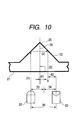
- FIG. 10 shows a case where the center of the light path (optical axis) is deviated right from the prism center line 35 by an amount of offset (deviation) 41.
- the deviation is not caused intentionally but is an indispensable deviation due to the accuracy of sensor parts, the mounting accuracy of the sensor parts, and the positional accuracy and the mounting accuracy of the prism resulting from the ink tank being mounted.
- the light emitted from the light emitting device 22 is displaced from the optical axis of the light receiving device 23 due to the occurrence of deviation of the optical axis (optical axis deviation) 42.
- an amount of deviation 42 of the optical axis of the light receiving device is theoretically twice as large as the amount of deviation 41.
- the intermediate axis of the lens interval 30 must be disposed in alignment with the prism center line 35 more accurately.
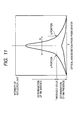
- FIG. 11 explains the relationship between the amount of deviation of the light sensor described above and the distribution of intensity of light that reaches the light receiving sensor.
- the intensity of reflected light has a value greatly larger than the threshold value for determining ink presence and absence.
- an increase in the amount deviation abruptly decreases an amount of received light, and when the amount of deviation is in the range less than a portion "a" and in the range larger than a point "b" in FIG. 11, the intensity of reflected light has a value less than the threshold value, and thus the ink presence and absence cannot be correctly determined.
- the ink tank Since the ink tank is mounted on a moving portion of an ink jet recording apparatus, in particular, on a carriage in many cases, it must be aligned with a pinpoint accuracy.
- the position of the prism must be accurately determined from the position of the ink tank determined with respect to the ink jet recording apparatus.
- the prism must be formed in a precise shape because it is an optically precise prism.
- a space called a relief is ordinarily formed in a molded product, the relief cannot be freely designed because it must be formed at a position offset from an optical path.
- an olefin resin is most preferable as a material which has good balance in reasonable price, chemical stability, and moldability as well as permits light to pass therethrough.
- a polypropylene resin is most suitable when injection moldability and mechanical rigidity are taken into consideration.
- an amount of background reflection 70 is increased by irregular reflection in the ink tank when ink exists therein and background reflected light reaches the light receiving device, from which an error region 71 occurs and an erroneous determination that "ink is absent" is made thereby.
- An object of the present invention which was devised to overcome the conventional cost increasing problem in order to construct the prism remaining amount detection mechanism described above, is to provide a low price ink jet recording apparatus with users as a result that an ink tank (liquid accommodation container), which is less expansive and can detect a remaining amount of ink while operating stably, can be provided. More specifically, an object of the present invention is to provide a highly reliable ink tank at low cost which can detect a remaining amount of ink in an exchangeable ink tank which supplies ink to an ink jet recording head and has an optical reflection mechanism for detecting the remaining amount of ink.
- the present invention relates to a liquid accommodation container for accommodating a liquid which includes walls for constituting the liquid accommodation container, a liquid accommodation chamber formed in the liquid accommodation container, a liquid supply port formed through one of the walls of the liquid accommodation container for supplying the liquid accommodated in the container to the outside, and an optical member disposed on the one of the walls, wherein a part of the optical member faces inward of the liquid accommodation chamber and has a function for reflecting light, which is incident from the outside, to the outside when no liquid is present in the liquid accommodation chamber and not reflecting the light, which is incident from the outside, to the outside when the liquid is present in the liquid accommodation chamber, and when the optical characteristics of a material of the liquid accommodation container are measured based on a standard according to JIS K7105, the material has optical characteristics which are equivalent to the optical characteristics that a transmittance of all light beams is 80% or more and a Haze value is equal to or more than 75% and equal to or less than 85%.
- a measured sample is a rectangular parallelepiped which constitutes the liquid accommodation container and has a square cross section with each side of 40 mm and a thickness of 1.7 mm.
- the optical member is molded integrally with the liquid accommodation container.
- the optical member is a member having two reflection surfaces.
- the optical member is composed of an olefin resin material containing no clearing agent.
- the liquid accommodation container includes a negative pressure generation member accommodation chamber for accommodating a negative pressure generation member and having a liquid supply port and an atmosphere communication unit, a liquid accommodation chamber having a communication unit for communicating with the negative pressure generation member accommodation chamber as well as forming a substantially hermetically sealed chamber, and an optical member for detecting the presence or absence of a liquid accommodated in the liquid accommodation chamber, wherein ink is poured into the liquid accommodation container such that at least the optical member is dipped in the ink.
- the optical member has such characteristics as to gently changing the intensity of light (FIG. 2) so that the light emitted from a light emitting device of a light sensor is reflected by the optical member while being scattered thereby and incident on a light receiving device of the light sensor. Accordingly, even if a light path (so-called optical axis), which is uniquely determined from the light emitting device to the light receiving device passing through the optical member, is displaced by the influence of a part accuracy and a mounting accuracy, a position alignment accuracy of the light sensor and the liquid accommodation container is eased. With the above arrangement, a remaining amount of a liquid can be more securely detected, and it is not necessary to enhance the position alignment accuracy using a costly means.
- a light path so-called optical axis
- presence or absence of the liquid remaining in the liquid accommodation container can be sufficiently detected even if the light sensor is not in alignment with the optical axis of the optical member by scattering the light emitted from the light sensor by the optical member.
- parts and systems can be simplified, and an ink tank by which the remaining amount can be detected with high reliability can be provided at a low price.
- Table 1 shows the optical characteristics of a material constituting an ink tank and a prism of a first embodiment of the present invention, the optical characteristics of a material constituting a conventional ink tank, and the dimensions of the respective prisms.
- the optical characteristics of the materials constituting the ink tanks were measured according to JIS K7105. Note that since it was difficult to measure the optical characteristics of the material of a prism portion of the ink tank due to its shape, they were measured as to the wall portion constituting the ink tank other than the prism portion.
- the wall of the ink tank measured in the embodiment had a thickness "t" of 1.7 mm.
- Prism height Transmittance of all light beams Diffusion ratio
- the material used in the embodiments is a resin having a feature that it has a high light transmitting property and that light is liable to be scattered in the resin.
- FIG. 1 shows a behavior of light traveling in the prism of the ink tank according to the first embodiment of the present invention.
- the light which has entered into the prism, is dispersed in a large region by the occurrence of appropriate scattering light 80 although its intensity is reduced. As a result, the region, in which prism refection can be used, is increased.
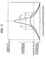
- FIG. 2 shows a comparison between the characteristics of a prism composed of a conventional material having high transparence and those of a prism composed of the material of the embodiments.
- a "threshold value" in the figure shows the intensity of reflected light for determining ink presence and absence.
- the conventional material is an olefin resin material containing a clearing agent
- the material of the embodiment is an olefin resin material containing no clearing agent.
- FIG. 2 shows a deviation of optical axis which can be recognized when ink is absent by a conventional allowable value 82 and an allowable value 81 of the embodiment.
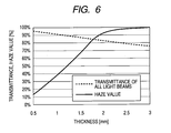
- the Haze value when the Haze value is extremely increased, a defect occurs in that an amount of ink cannot be visually confirmed from the outside.
- the visual confirmation of the amount of ink does not directly relate to the present invention, it is a very important factor for the confirmation of reliability that a user can confirm the amount of ink by his or her eyes in actual use, in addition to that it is detected by the apparatus.
- the Haze value when the Haze value is equal to or less than 70%, light is less scattered and the characteristics of the prism become near to the characteristics of the conventional prism shown in FIG. 8 described above. Accordingly, it is necessary that the Haze value be larger than 70% and less than 90% and preferably be equal to or larger than 75% and equal to or less than 85%.
- the transmittance of all light beams is equal to or less than 75%, since light itself is absorbed into the prism, the transmittance of all light beams is preferably 80% or more.
- FIG. 3 shows a behavior of light traveling in a prism 20 of an ink tank according to a second embodiment of the present invention.
- the second embodiment shows an example that light is scattered while maintaining the degree of transparence of a material itself constituting the prism 20 to a conventional value (for example, a Haze value of 27%).
- the second embodiment intends to disperse light by intentionally reducing the degree of flatness of the surfaces 100, 101, and 102 of the prism 20.
- the prism 20 When the prism 20 is formed of plastic by injection molding, the prism 20 can be formed in a shape, which can disperse light on the surfaces thereof, by a design of a metal mold.
- the portions of the prism 20, which are subjected to a non-mirror-finished surface treatment and formed to rough surfaces, are the surfaces 100 and 101 that are two slanting surfaces thereof and at least the surface 102 of the wall of the ink tank which corresponds to the portion of the ink tank where the prism 20 is formed.
- a test piece which has been subjected to the same treatment, has a square cross section with each side of 40 mm, a thickness of 1.7 mm, has a transmittance of all light beams of 80% or more and a Haze value equal to or more than 75% and equal to or less than 85% as a result of measurement of the optical characteristics thereof executed based on a standard according to JIS K7105.
- a prism having optical characteristics equivalent to the above optical characteristics is formed, the same effect as the first embodiment can be obtained.
- the second embodiment is advantageous also in that the dispersion of light can be easily adjusted in design because it can be controlled by the shape of the metal mold.
- FIG. 4 shows a behavior of light traveling in a prism 20 of an ink tank according to a third embodiment of the present invention.
- a light dispersing sheet 111 for dispersing light is disposed on the portion of the bottom 21 of the ink tank which corresponds to at least the prism 20.
- the basic structure of the ink tank is the same as that of the conventional ink tank (refer to FIGS. 7A and 7B), and the dispersion of light can be finely adjusted by selecting the light dispersing sheet 111 bonded to the prism 20 depending on a type and sensitivity of the sensors of a light emitting device 22 and a light receiving device 23 and on a threshold value for determining ink presence and absence.
- a test piece which has a square cross section with each side of 40 mm and a thickness of 1.7 mm and to which the above sheet is bonded, has a transmittance of all light beams of 80% or more and a Haze value equal to or more than 75% and equal to or less than 85% as a result of measurement of the optical characteristics thereof executed based on the standard according to JIS K7105.
- a prism having optical characteristics equivalent to the above optical characteristics is formed, the same effect as the first embodiment can be obtained.
- the third embodiment has an advantage in that it is suitable for a small item production and that and can be customized to various ink tanks in a short preparation time.
- FIG. 5 shows a behavior of light in a prism 60 of an ink tank according to a fourth embodiment of the present invention.
- the prism 60 has an optically reflecting portion having four surfaces in place of a conventional triangular shape.
- the prism 60 is formed of a material, which has a square cross section with each side of 40 mm, a thickness of 1.7 mm, and such optical characteristics that a transmittance of all light beams is 80% or more and a Haze value is equal to or more than 75% and equal to or less than 85% when they are measured based on the standard according to JIS K7105.
- the fourth embodiment is effective when, for example, the optically reflecting portion requires a mechanical strength.
- the optical characteristics of a prism portion acting as the optically reflecting portion are characterized by the numerical values obtained by measuring the optical characteristics of the test piece having the cross section with each side of 40 mm and the thickness of 1.7 mm based on the standard according to JIS K7105 for convenience. This is because that the transmittance of all light beams and the Haze value change depending on the thickness of the material.
- a selected material is the same as the material of the present invention by molding the test piece having the square cross section with each side of 40 mm and the thickness of 1.7 mm.
- the inventors have verified the material of the present invention likewise using test pieces having the square cross section with each side of 40 mm and various thicknesses.
- Ink is poured into the ink tank such that at least the prism portion is dipped in the ink.
- a prism of an ink tank has a function for reflecting light, which is incident from the outside, to the outside when no liquid is present in a liquid chamber and not reflecting the light, which is incident from the outside, to the outside when a liquid is present in the liquid chamber, and when the optical characteristics of a material constituting the liquid accommodation container are measured based on a standard according to JIS K7105, the material has optical characteristics equivalent to such optical characteristics that a transmittance of all light beams is 80% or more and a Haze value is equal to or more than 75% and equal to or less than 85%.
Landscapes
- Ink Jet (AREA)
- Details Of Rigid Or Semi-Rigid Containers (AREA)
Applications Claiming Priority (2)
| Application Number | Priority Date | Filing Date | Title |
|---|---|---|---|
| JP2003280025A JP2005041183A (ja) | 2003-07-25 | 2003-07-25 | 液体収容容器 |
| JP2003280025 | 2003-07-25 |
Publications (2)
| Publication Number | Publication Date |
|---|---|
| EP1500511A2 true EP1500511A2 (fr) | 2005-01-26 |
| EP1500511A3 EP1500511A3 (fr) | 2005-09-21 |
Family
ID=33487725
Family Applications (1)
| Application Number | Title | Priority Date | Filing Date |
|---|---|---|---|
| EP04017323A Withdrawn EP1500511A3 (fr) | 2003-07-25 | 2004-07-22 | Réservoir pour des liquides |
Country Status (5)
| Country | Link |
|---|---|
| US (1) | US7147312B2 (fr) |
| EP (1) | EP1500511A3 (fr) |
| JP (1) | JP2005041183A (fr) |
| KR (1) | KR100633817B1 (fr) |
| CN (1) | CN1307054C (fr) |
Families Citing this family (15)
| Publication number | Priority date | Publication date | Assignee | Title |
|---|---|---|---|---|
| CN2850919Y (zh) * | 2005-11-18 | 2006-12-27 | 珠海纳思达电子科技有限公司 | 一种喷墨打印机墨盒 |
| US7950791B2 (en) * | 2007-10-29 | 2011-05-31 | Hewlett-Packard Development Company, L.P. | Ink level detection by electronic means |
| CN201143794Y (zh) * | 2007-12-10 | 2008-11-05 | 珠海纳思达电子科技有限公司 | 一种喷墨打印机的墨盒 |
| JP2010012775A (ja) * | 2008-06-06 | 2010-01-21 | Canon Inc | インクタンクおよび液体収納容器 |
| US20120236087A1 (en) * | 2009-09-28 | 2012-09-20 | Pelikan Hardcopy Production Ag | Ink cartridge for inkjet printers |
| JP5585154B2 (ja) * | 2010-03-25 | 2014-09-10 | セイコーエプソン株式会社 | 液体噴射システム |
| JP5884296B2 (ja) * | 2011-05-20 | 2016-03-15 | セイコーエプソン株式会社 | 液体容器、液体容器を備えた液体噴射装置、および液体容器の製造方法 |
| JP5884302B2 (ja) * | 2011-06-06 | 2016-03-15 | セイコーエプソン株式会社 | 射出成形方法、射出成形品、インクタンク、記録装置及び射出成形金型 |
| US8727467B2 (en) * | 2012-02-23 | 2014-05-20 | Seiko Epson Corporation | Liquid consumption device and method |
| JP5949905B2 (ja) * | 2012-03-26 | 2016-07-13 | コニカミノルタ株式会社 | プリズム及びセンサーチップ |
| JP6210300B2 (ja) * | 2013-11-29 | 2017-10-11 | セイコーエプソン株式会社 | 液体消費装置 |
| JP6287322B2 (ja) * | 2014-02-25 | 2018-03-07 | セイコーエプソン株式会社 | 液体消費装置及び液体消費装置の制御方法 |
| CN110031433A (zh) * | 2019-05-28 | 2019-07-19 | 南京奇崛电子科技有限公司 | 一种光反射镜浊度传感器 |
| JP7805797B2 (ja) * | 2021-01-29 | 2026-01-26 | キヤノン株式会社 | インク容器、及びインクジェット記録装置 |
| CN114083904A (zh) * | 2021-10-26 | 2022-02-25 | 厦门微亚智能科技有限公司 | 一种uv树脂胶水的供墨系统 |
Citations (5)
| Publication number | Priority date | Publication date | Assignee | Title |
|---|---|---|---|---|
| JPH07218321A (ja) | 1994-02-07 | 1995-08-18 | Fuji Xerox Co Ltd | インクタンク |
| JPH08112907A (ja) | 1994-10-14 | 1996-05-07 | Canon Inc | インクジェット記録装置 |
| JPH0929989A (ja) | 1995-07-14 | 1997-02-04 | Canon Inc | インク有無検出装置、インクタンク、キット、記録ユニット、記録装置、および情報処理システム |
| JP2000043287A (ja) | 1998-07-30 | 2000-02-15 | Canon Inc | インクジェット印刷装置 |
| JP2002321388A (ja) | 1993-05-26 | 2002-11-05 | Canon Inc | インクタンク、インクジェット記録装置、および検出方法 |
Family Cites Families (10)
| Publication number | Priority date | Publication date | Assignee | Title |
|---|---|---|---|---|
| US3221210A (en) * | 1963-04-24 | 1965-11-30 | John O Mullings | Circuit for indicating failure in automobile headlights circuits |
| ATE191886T1 (de) * | 1993-05-26 | 2000-05-15 | Canon Kk | Tintenstrahlaufzeichnungsvorrichtung |
| JPH07237300A (ja) | 1994-02-09 | 1995-09-12 | Copyer Co Ltd | インクジェット記録装置 |
| DE69529792T2 (de) * | 1994-10-14 | 2003-10-23 | Canon K.K., Tokio/Tokyo | Tintenstrahlaufzeichnungsgerät mit Restantenüberwachung und Verfahren dazu |
| US5997121A (en) * | 1995-12-14 | 1999-12-07 | Xerox Corporation | Sensing system for detecting presence of an ink container and level of ink therein |
| JPH10323993A (ja) * | 1997-02-19 | 1998-12-08 | Canon Inc | 検出システム、該検出システムを用いる液体吐出記録装置と液体収納容器、及び、光量変化受光システム |
| JP3530727B2 (ja) * | 1997-11-14 | 2004-05-24 | キヤノン株式会社 | 記録装置及び記録制御方法 |
| JP3595743B2 (ja) * | 1998-10-27 | 2004-12-02 | キヤノン株式会社 | インクタンク、及び、そのインクタンクを含むカートリッジ、及び、そのカートリッジを用いる記録装置 |
| JP2001063099A (ja) * | 1999-06-23 | 2001-03-13 | Canon Inc | インクタンク、インクタンクを搭載するインクジェット記録装置、およびインクタンクの包装パッケージ |
| DE10292319B4 (de) * | 2001-06-01 | 2012-03-08 | Daicel Chemical Industries, Ltd. | Lichtstreuender Film, ebene Lichtquellen-Einrichtung und Flüssigkristall-Anzeige-Vorrichtung, in denen er verwendet wird |
-
2003
- 2003-07-25 JP JP2003280025A patent/JP2005041183A/ja active Pending
-
2004
- 2004-07-07 CN CNB2004100624393A patent/CN1307054C/zh not_active Expired - Fee Related
- 2004-07-09 US US10/886,552 patent/US7147312B2/en not_active Expired - Fee Related
- 2004-07-22 EP EP04017323A patent/EP1500511A3/fr not_active Withdrawn
- 2004-07-23 KR KR1020040057413A patent/KR100633817B1/ko not_active Expired - Fee Related
Patent Citations (5)
| Publication number | Priority date | Publication date | Assignee | Title |
|---|---|---|---|---|
| JP2002321388A (ja) | 1993-05-26 | 2002-11-05 | Canon Inc | インクタンク、インクジェット記録装置、および検出方法 |
| JPH07218321A (ja) | 1994-02-07 | 1995-08-18 | Fuji Xerox Co Ltd | インクタンク |
| JPH08112907A (ja) | 1994-10-14 | 1996-05-07 | Canon Inc | インクジェット記録装置 |
| JPH0929989A (ja) | 1995-07-14 | 1997-02-04 | Canon Inc | インク有無検出装置、インクタンク、キット、記録ユニット、記録装置、および情報処理システム |
| JP2000043287A (ja) | 1998-07-30 | 2000-02-15 | Canon Inc | インクジェット印刷装置 |
Also Published As
| Publication number | Publication date |
|---|---|
| US7147312B2 (en) | 2006-12-12 |
| CN1307054C (zh) | 2007-03-28 |
| US20050018007A1 (en) | 2005-01-27 |
| KR100633817B1 (ko) | 2006-10-16 |
| JP2005041183A (ja) | 2005-02-17 |
| KR20050012664A (ko) | 2005-02-02 |
| CN1576017A (zh) | 2005-02-09 |
| EP1500511A3 (fr) | 2005-09-21 |
Similar Documents
| Publication | Publication Date | Title |
|---|---|---|
| US7147312B2 (en) | Liquid accommodation container | |
| CN103373076B (zh) | 墨容纳装置和适配器 | |
| EP1391306B1 (fr) | Réservoir pour liquide, procédé de détection de la quantité de liquide dans le réservoir pour liquide et appareil d'enregistrement par éjection de liquide | |
| EP2103434B1 (fr) | Cartouches d'encre, dispositif d'identification et procédé d'identification de cartouche d'encre | |
| WO2005071368A2 (fr) | Appareil et procede de detection du niveau d'un liquide | |
| JP4576871B2 (ja) | 収容物検出装置、容器、及びインクジェットプリンタ | |
| US7040728B2 (en) | Geometry for a dual level fluid quantity sensing refillable fluid container | |
| KR20070076431A (ko) | 반사형 광학센서 및 측정면의 표면조도 검출방법 | |
| EP2214910B1 (fr) | Cartouche d'encre ayant un prisme | |
| US20210373159A1 (en) | ToF DISTANCE SENSOR AND ELECTRONIC DEVICE | |
| CN101668638B (zh) | 用于测量容器中的墨位的设备和方法 | |
| US20090303298A1 (en) | Liquid container | |
| US8270449B2 (en) | Liquid supply devices and liquid cartridges | |
| CN217863353U (zh) | 一种墨盒 | |
| JP2002264355A (ja) | 液面検知装置およびインクジェットプリンタ | |
| JP4872488B2 (ja) | インクカートリッジおよびインクジェット記録装置 | |
| JP7536581B2 (ja) | 液体残量検知装置 | |
| US7507981B2 (en) | System for identifying a characteristic of a printing media | |
| JP2007144770A (ja) | インクタンクおよび記録装置 | |
| JP2006264234A (ja) | インクタンクおよびインク残量検知手段 | |
| JP7012971B2 (ja) | 光学式レベル検出装置及びその計量方法 | |
| EP3492882B1 (fr) | Capteur de détection de niveau de liquide et appareil de test d'échantillon | |
| JP2003106891A (ja) | 液体検出センサ | |
| KR0184130B1 (ko) | 잉크 카트리지 감지 장치 | |
| JP2000127432A (ja) | 液体収納容器、及び、その液体収納容器を含むカートリッジ、及び、そのカートリッジを用いる記録装置、及び、液体吐出記録装置 |
Legal Events
| Date | Code | Title | Description |
|---|---|---|---|
| PUAI | Public reference made under article 153(3) epc to a published international application that has entered the european phase |
Free format text: ORIGINAL CODE: 0009012 |
|
| AK | Designated contracting states |
Kind code of ref document: A2 Designated state(s): AT BE BG CH CY CZ DE DK EE ES FI FR GB GR HU IE IT LI LU MC NL PL PT RO SE SI SK TR |
|
| AX | Request for extension of the european patent |
Extension state: AL HR LT LV MK |
|
| PUAL | Search report despatched |
Free format text: ORIGINAL CODE: 0009013 |
|
| AK | Designated contracting states |
Kind code of ref document: A3 Designated state(s): AT BE BG CH CY CZ DE DK EE ES FI FR GB GR HU IE IT LI LU MC NL PL PT RO SE SI SK TR |
|
| AX | Request for extension of the european patent |
Extension state: AL HR LT LV MK |
|
| 17P | Request for examination filed |
Effective date: 20060321 |
|
| AKX | Designation fees paid |
Designated state(s): AT BE BG CH CY CZ DE DK EE ES FI FR GB GR HU IE IT LI LU MC NL PL PT RO SE SI SK TR |
|
| 17Q | First examination report despatched |
Effective date: 20071106 |
|
| STAA | Information on the status of an ep patent application or granted ep patent |
Free format text: STATUS: THE APPLICATION HAS BEEN WITHDRAWN |
|
| 18W | Application withdrawn |
Effective date: 20130325 |