EP1495701A1 - Joining element for cooking untensil called couscous vessel - Google Patents
Joining element for cooking untensil called couscous vessel Download PDFInfo
- Publication number
- EP1495701A1 EP1495701A1 EP03360084A EP03360084A EP1495701A1 EP 1495701 A1 EP1495701 A1 EP 1495701A1 EP 03360084 A EP03360084 A EP 03360084A EP 03360084 A EP03360084 A EP 03360084A EP 1495701 A1 EP1495701 A1 EP 1495701A1
- Authority
- EP
- European Patent Office
- Prior art keywords
- couscous
- cooking
- couscoussier
- called
- vessel
- Prior art date
- Legal status (The legal status is an assumption and is not a legal conclusion. Google has not performed a legal analysis and makes no representation as to the accuracy of the status listed.)
- Granted
Links
Images
Classifications
-
- A—HUMAN NECESSITIES
- A47—FURNITURE; DOMESTIC ARTICLES OR APPLIANCES; COFFEE MILLS; SPICE MILLS; SUCTION CLEANERS IN GENERAL
- A47J—KITCHEN EQUIPMENT; COFFEE MILLS; SPICE MILLS; APPARATUS FOR MAKING BEVERAGES
- A47J27/00—Cooking-vessels
- A47J27/04—Cooking-vessels for cooking food in steam; Devices for extracting fruit juice by means of steam ; Vacuum cooking vessels
- A47J27/05—Tier steam-cookers, i.e. with steam-tight joints between cooking-vessels stacked while in use
Definitions
- the present invention relates to a seal device for cooking utensil called couscoussier for the preparation of the couscous.
- a couscous basically two parts, a part consisting of a pot, and a high part nestable on said lower part and consisting of a perforated bottom container.
- the lower part is intended for cooking vegetables and meat entering the composition of couscous, while the upper part is intended for cooking semolina by means of steam emanating from said lower part.
- the preparer wraps usually the upper part of couscous for a piece of cloth preferably wet, such as a towel, which is inserted between said upper part and the lower part for make the seal.
- the tightness achieved is however not perfect because it is not easy to marry perfectly the outer contour of the nestable section of the upper part, and the inner contour of the opening of the lower part.
- this way of proceeding presents a risk of inflammation of the piece of fabric.
- the present invention aims to propose a device for joint for cooking utensil called couscous for the preparation of couscous, making it possible to remedy the various disadvantages mentioned above, and which is adaptable to all existing couscous makers.
- the cooking device for a cooking utensil Couscoussier for the preparation of couscous comprising a low part shaped pot and a high part shaped container with perforated bottom, according to the invention is characterized essentially in that it consists of a strip of material natural or synthetic plastic, arranged in a portion of tube, intended to cover externally the junction area of the upper part and the lower part of the couscoussier.
- the plastic strip is sufficiently deformable for allow its adaptation to couscousers of diameters different, in order to marry the outline.
- the device comprises means capable of enabling its adaptation on high parts of various forms.
- the means capable of enabling it to be adapted to upper parts of various shapes consist of at least one external device groove or the like.
- Such a groove, or several, promotes the wrapping of the lower part of the upper part when it presents a curved shape.
- the device comprises externally means of gripping.
- the gripping means consist of tabs protruding outward.
- the device is made of latex or a material similar synthetic.
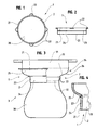
- FIG. 1 represents an elevational view of a device for seal according to the invention.
- Figure 2 shows a plan view of the same seal.
- Figure 3 shows an elevational view with partial section a couscoussier equipped with a sealing device according to the invention.
- FIG. 4 represents a partial schematic sectional view of the device according to the invention.
- a device for joint 1 for cooking utensils called couscoussier for the preparation of the couscous according to the invention.
- This joint device 1 is in the form of a strip 2 of elastic material arranged in a flat ring or more exactly one portion of tube, expandable in the direction diametrical.
- the strip 2 has a smooth inner wall 20 and a wall 21 of an edge of which protrude towards the outside of the tongues 22 gripping, in this case to number of four.
- This couscoussier 3 comprises in a traditional manner two parts, a lower part consisting of a cooking pot, and a upper part 31 consisting of a perforated bottom container, not visible, whose base 32 is shaped to allow its nesting just in the opening of the lower part 30.
- the joint device 1 according to the invention is arranged on the couscoussier 3 in order to cover the J junction zone of the upper part 31 and the lower part 30 to quench assembly.
- the seal device 1 thus covers the upper end 33 of the lower part 30 and the portion lower 34 of the upper portion 31 extending above the base 32.
- the couscoussier 3 is of form traditional curved, that is to say that the portion 34 presents successively above the base 32, a concave zone 35 and a convex zone 36.
- the outer wall 21 of the strip 2 has a peripheral groove 23 allowing the band 2, as is visible in Figure 4, to marry at the most just the curve of the couscoussier 3 and in particular of the portion 34.
- joint device 1 can be perfectly adaptable to all forms of couscous.
- the installation of the joint device 1 on the couscoussier 3 can be done in the following way, the lower part 24 of Band 2, mainly its portion below the groove 23 is placed on the upper end 33 of the lower part 30, while its upper part 25 is folded on the bottom part 24 the time to place the top part 31 on the lower part 30. Then, with the help of the tongues of gripping 22, the upper part 25 is brought on the portion 24 of the high bet 31 of the couscoussier 3.
- the joint device 1 adapts perfectly, without resorting to the faculties of the grooves 23.
- the device of joint according to the invention makes it possible to guarantee the tightness of the junction high and low parts, so that you get a constant vapor diffusion, ensuring perfect cooking of semolina.
Abstract
Description
La présente invention a pour objet un dispositif de joint pour ustensile de cuisson dit couscoussier pour la préparation du couscous.The present invention relates to a seal device for cooking utensil called couscoussier for the preparation of the couscous.
De manière traditionnelle, un couscoussier comporte essentiellement deux parties, une partie consistant en une marmite, et une partie haute emboítable sur ladite partie basse et consistant en un récipient à fond ajouré. La partie basse est destinée à la cuisson des légumes et de la viande entrant dans la composition du couscous, tandis que la partie haute est destinée à la cuisson de la semoule au moyen de la vapeur émanant de ladite partie basse.In a traditional way, a couscous basically two parts, a part consisting of a pot, and a high part nestable on said lower part and consisting of a perforated bottom container. The lower part is intended for cooking vegetables and meat entering the composition of couscous, while the upper part is intended for cooking semolina by means of steam emanating from said lower part.
Il existe essentiellement deux types de couscoussier, lesquels se différencient par leur forme, à savoir le premier, traditionnel, qui comporte deux parties haute et basse de forme galbée la section de la partie haute d'emboítement présentant un profil de section en forme de S, tandis que le second présente une forme globalement cylindrique, les parties basse et haute étant de même diamètre. D'autre part, il existe des couscoussiers de différentes contenances et donc de différents diamètres.There are basically two types of couscous differentiate themselves by their shape, namely the first, traditional, which has two high and low form parts curved section of the upper part of nested with a section profile in the shape of S, while the second presents a generally cylindrical shape, the low and high parts being of the same diameter. On the other hand, there are Couscoussiers of different capacities and therefore of different diameters.
Les couscoussiers actuellement utilisés présentent l'inconvénient d'une étanchéité imparfaite entre les parties haute et basse, en sorte qu'une quantité de vapeur s'échappe vers l'extérieur et ne traverse pas la semoule qui nécessite alors un temps de cuisson plus long, ce qui peut par ailleurs être préjudiciable à la cuisson des légumes et de la viande.Couscoussiers currently used present the disadvantage of imperfect sealing between the parties high and low, so that a quantity of steam escapes outward and does not cross the semolina that requires then a longer cooking time, which can otherwise be detrimental to cooking vegetables and meat.
Pour pallier cet inconvénient, le préparateur enveloppe généralement la partie haute du couscoussier d'un morceau de tissu de préférence mouillé, tel qu'une serviette, qui s'intercale entre ladite partie haute et la partie basse pour réaliser l'étanchéité. L'étanchéité réalisée n'est cependant pas parfaite du fait notamment qu'il n'est pas aisé d'épouser parfaitement le contour extérieur de la section emboítable de la partie haute, et le contour intérieur de l'ouverture de la partie basse. De plus, cette manière de procéder présente un risque d'inflammation du morceau de tissu.To overcome this drawback, the preparer wraps usually the upper part of couscous for a piece of cloth preferably wet, such as a towel, which is inserted between said upper part and the lower part for make the seal. The tightness achieved is however not perfect because it is not easy to marry perfectly the outer contour of the nestable section of the upper part, and the inner contour of the opening of the lower part. Moreover, this way of proceeding presents a risk of inflammation of the piece of fabric.
La présente invention a pour but de proposer un dispositif de joint pour ustensile de cuisson dit couscoussier pour la préparation du couscous, permettant de remédier aux divers inconvénients précités, et qui est adaptable sur tous les couscoussiers existants.The present invention aims to propose a device for joint for cooking utensil called couscous for the preparation of couscous, making it possible to remedy the various disadvantages mentioned above, and which is adaptable to all existing couscous makers.
Le dispositif de joint pour ustensile de cuisson dit couscoussier pour la préparation du couscous, comprenant une partie basse en forme marmite et une partie haute en forme de récipient à fond ajouré, selon l'invention se caractérise essentiellement en ce qu'il consiste en une bande de matière plastique naturelle ou synthétique, agencée en une portion de tube, destinée à recouvrir extérieurement la zone de jonction de la partie haute et de la partie basse du couscoussier.The cooking device for a cooking utensil Couscoussier for the preparation of couscous, comprising a low part shaped pot and a high part shaped container with perforated bottom, according to the invention is characterized essentially in that it consists of a strip of material natural or synthetic plastic, arranged in a portion of tube, intended to cover externally the junction area of the upper part and the lower part of the couscoussier.
La bande de matière plastique est suffisamment déformable pour permettre son adaptation à des couscoussiers de diamètres différents, en sorte d'en épouser le contour.The plastic strip is sufficiently deformable for allow its adaptation to couscousers of diameters different, in order to marry the outline.
Selon une caractéristique additionnelle du dispositif selon l'invention, il comporte des moyens aptes à permettre son adaptation sur des parties hautes de formes variées.According to an additional feature of the device according to the invention, it comprises means capable of enabling its adaptation on high parts of various forms.
Selon un mode de réalisation particulier du dispositif selon l'invention, les moyens aptes à permettre son adaptation sur des parties hautes de formes variées consistent en au moins une rainure ou analogue périphérique extérieure. According to a particular embodiment of the device according to the invention, the means capable of enabling it to be adapted to upper parts of various shapes consist of at least one external device groove or the like.
Une telle rainure, ou plusieurs, favorise l'enveloppement de la partie inférieure de la partie haute lorsque celle-ci présente une forme galbée.Such a groove, or several, promotes the wrapping of the lower part of the upper part when it presents a curved shape.
Selon une autre caractéristique additionnelle du dispositif selon l'invention, il comporte extérieurement des moyens de préhension.According to another additional feature of the device according to the invention, it comprises externally means of gripping.
De manière avantageuse, les moyens de préhension consistent en des languettes faisant saillie vers l'extérieur.Advantageously, the gripping means consist of tabs protruding outward.
Selon une autre caractéristique additionnelle du dispositif selon l'invention, il est réalisé en latex ou en un matériau synthétique similaire.According to another additional feature of the device according to the invention, it is made of latex or a material similar synthetic.
Les avantages et les caractéristiques du dispositif selon l'invention, ressortiront plus clairement de la description qui suit et qui se rapporte au dessin annexé, lequel en représente un mode de réalisation non limitatif.The advantages and characteristics of the device according to invention, will become clearer from the description which follows and which refers to the annexed drawing, which represents a non-limiting embodiment.
La figure 1 représente une vue en élévation d'un dispositif de joint selon l'invention.FIG. 1 represents an elevational view of a device for seal according to the invention.
La figure 2 représente une vue en plan du même joint.Figure 2 shows a plan view of the same seal.
La figure 3 représente une vue élévation avec coupe partielle d'un couscoussier équipé d'un dispositif de joint selon l'invention.Figure 3 shows an elevational view with partial section a couscoussier equipped with a sealing device according to the invention.
La figure 4 représente une vue schématique partielle en coupe du dispositif selon l'invention. FIG. 4 represents a partial schematic sectional view of the device according to the invention.
En référence aux figures 1 et 2, on peut voir un dispositif de
joint 1 pour ustensile de cuisson dit couscoussier pour la
préparation du couscous selon l'invention.With reference to FIGS. 1 and 2, one can see a device for
Ce dispositif de joint 1 se présente sous la forme d'une bande 2
de matière élastique agencée en un anneau plat ou plus
exactement une portion de tube, extensible dans le sens
diamétral.This
La bande 2 comporte une paroi intérieure 20 lisse et une paroi
extérieure 21 d'un bord de laquelle font saillie vers
l'extérieur des languettes 22 de préhension, en l'occurrence au
nombre de quatre.The
En référence maintenant à la figure 3, on peut voir un ustensile de cuisson 3 dit couscoussier pour la préparation du couscous.Referring now to Figure 3, one can see a utensil cooking 3 said couscoussier for the preparation of couscous.
Ce couscoussier 3 comporte de manière traditionnelle deux
parties, une partie basse 30 consistant en une marmite, et une
partie haute 31 consistant en un récipient à fond ajouré, non
visible, dont la base 32 est de forme apte à permettre son
emboítement au plus juste dans l'ouverture de la partie basse
30.This couscoussier 3 comprises in a traditional manner two
parts, a lower part consisting of a cooking pot, and a
Le dispositif de joint 1 selon l'invention est disposé sur le
couscoussier 3 en sorte de recouvrir la zone J de jonction de la
partie haute 31 et de la partie basse 30 pour étancher
l'assemblage. Le dispositif de joint 1 recouvre ainsi
l'extrémité supérieure 33 de la partie basse 30 et la portion
inférieure 34 de la partie haute 31 s'étendant au-dessus de la
base 32.The
Dans l'exemple représenté le couscoussier 3 est de forme
traditionnelle galbée, c'est à dire que la portion 34 présente
successivement au-dessus de la base 32, une zone concave 35 puis
une zone convexe 36. In the example shown the couscoussier 3 is of form
traditional curved, that is to say that the
Aussi, pour faciliter la mise en place, et afin d'éviter la
formation de plis préjudiciables d'une part à l'étanchéité, et
d'autre part au parfait positionnement de la bande 2 sur la
portion 34, la paroi extérieure 21 de la bande 2 présente une
rainure périphérique 23 permettant à la bande 2, comme cela est
visible sur la figure 4, d'épouser au plus juste le galbe du
couscoussier 3 et notamment de la portion 34.Also, to facilitate the setting up, and in order to avoid the
forming folds detrimental on the one hand to the seal, and
on the other hand to the perfect positioning of the
On notera qu'il est parfaitement possible de prévoir d'autres
rainures périphériques, qu'elles soient internes ou externes,
afin que le dispositif de joint 1 puisse être parfaitement
adaptable à toutes les formes de couscoussier.Note that it is perfectly possible to foresee other
peripheral grooves, whether internal or external,
so that the
La mise en place du dispositif de joint 1 sur le couscoussier 3
peut être réalisée de la manière suivante, la partie inférieure
24 de la bande 2, à savoir principalement sa portion en deçà de
la rainure 23, est placée sur l'extrémité supérieure 33 de la
partie basse 30, tandis que sa partie supérieure 25 est repliée
sur la partie inférieure 24 le temps de placer la partie haute
31 sur la partie basse 30. Puis, en s'aidant des languettes de
préhension 22, la partie supérieure 25 est amenée sur la portion
24 de la parie haute 31 du couscoussier 3.The installation of the
L'enlèvement du dispositif de joint 1 est bien entendu réalisé
en procédant de manière inverse, en utilisant là-encore les
languettes 22.The removal of the
Dans le cas, non représenté, d'un couscoussier de type droit,
c'est-à-dire de forme globalement cylindrique où les parties
haute et basse sont de même diamètre, le dispositif de joint 1
s'adapte parfaitement, sans recourir aux facultés de la rainures
23.In the case, not shown, of a straight type couscoussier,
that is to say of generally cylindrical shape where the parts
high and low are the same diameter, the
Quel que soit le couscoussier utilisé, le dispositif de joint selon l'invention permet de garantir l'étanchéité de la jonction des parties haute et basse, en sorte que l'on obtient une diffusion de vapeur constante, assurant une parfaite cuisson de la semoule.Whatever the couscoussier used, the device of joint according to the invention makes it possible to guarantee the tightness of the junction high and low parts, so that you get a constant vapor diffusion, ensuring perfect cooking of semolina.
Claims (6)
Priority Applications (4)
| Application Number | Priority Date | Filing Date | Title |
|---|---|---|---|
| ES03360084T ES2295536T3 (en) | 2003-07-10 | 2003-07-10 | BOARD DEVICE FOR COOKING UTENSIL CALLED OLLA FOR CUSCUS. |
| DE60316677T DE60316677T2 (en) | 2003-07-10 | 2003-07-10 | Connecting element for cookware called Couscoustopf |
| EP03360084A EP1495701B1 (en) | 2003-07-10 | 2003-07-10 | Joining element for cooking untensil called couscous vessel |
| AT03360084T ATE374552T1 (en) | 2003-07-10 | 2003-07-10 | CONNECTING ELEMENT FOR COOKWARE CALLED COUSCOUS POT |
Applications Claiming Priority (1)
| Application Number | Priority Date | Filing Date | Title |
|---|---|---|---|
| EP03360084A EP1495701B1 (en) | 2003-07-10 | 2003-07-10 | Joining element for cooking untensil called couscous vessel |
Publications (2)
| Publication Number | Publication Date |
|---|---|
| EP1495701A1 true EP1495701A1 (en) | 2005-01-12 |
| EP1495701B1 EP1495701B1 (en) | 2007-10-03 |
Family
ID=33442889
Family Applications (1)
| Application Number | Title | Priority Date | Filing Date |
|---|---|---|---|
| EP03360084A Expired - Lifetime EP1495701B1 (en) | 2003-07-10 | 2003-07-10 | Joining element for cooking untensil called couscous vessel |
Country Status (4)
| Country | Link |
|---|---|
| EP (1) | EP1495701B1 (en) |
| AT (1) | ATE374552T1 (en) |
| DE (1) | DE60316677T2 (en) |
| ES (1) | ES2295536T3 (en) |
Citations (3)
| Publication number | Priority date | Publication date | Assignee | Title |
|---|---|---|---|---|
| US1408356A (en) * | 1922-02-28 | Double boiler | ||
| EP0165152A1 (en) * | 1984-05-28 | 1985-12-18 | Joel Barillot | Container and method of treating and sterilizing cooked food whereby the food components are separately stored and the cooking odours can migrate from one comportment to the other |
| FR2719882A1 (en) * | 1994-05-16 | 1995-11-17 | Kacimi Arezki | Sealing joint between cooking pot and steamer colander |
-
2003
- 2003-07-10 AT AT03360084T patent/ATE374552T1/en not_active IP Right Cessation
- 2003-07-10 ES ES03360084T patent/ES2295536T3/en not_active Expired - Lifetime
- 2003-07-10 DE DE60316677T patent/DE60316677T2/en not_active Expired - Fee Related
- 2003-07-10 EP EP03360084A patent/EP1495701B1/en not_active Expired - Lifetime
Patent Citations (3)
| Publication number | Priority date | Publication date | Assignee | Title |
|---|---|---|---|---|
| US1408356A (en) * | 1922-02-28 | Double boiler | ||
| EP0165152A1 (en) * | 1984-05-28 | 1985-12-18 | Joel Barillot | Container and method of treating and sterilizing cooked food whereby the food components are separately stored and the cooking odours can migrate from one comportment to the other |
| FR2719882A1 (en) * | 1994-05-16 | 1995-11-17 | Kacimi Arezki | Sealing joint between cooking pot and steamer colander |
Also Published As
| Publication number | Publication date |
|---|---|
| ATE374552T1 (en) | 2007-10-15 |
| ES2295536T3 (en) | 2008-04-16 |
| EP1495701B1 (en) | 2007-10-03 |
| DE60316677D1 (en) | 2007-11-15 |
| DE60316677T2 (en) | 2008-07-17 |
Similar Documents
| Publication | Publication Date | Title |
|---|---|---|
| EP1996052B1 (en) | Cover for culinary article with silicone gasket | |
| FR2600978A1 (en) | DISPENSING CAP WITH ROTATING CAP FOR PASTA PRODUCTS | |
| FR3070847A1 (en) | FOOD PREPARATION AND / OR COOKING ASSEMBLY FOR HOUSEHOLD KITCHEN ROBOT | |
| LU88170A1 (en) | CLOSURE ASSEMBLY FOR CONTAINER | |
| CH621986A5 (en) | ||
| FR2877195A1 (en) | BEVERAGE BOTTLE HOLDER OF PLASTIC MATERIAL | |
| EP1495701B1 (en) | Joining element for cooking untensil called couscous vessel | |
| FR2838038A1 (en) | Joint for couscous cooking utensil comprises pot shaped bottom part and top part in shape of container openwork bottom with tube shaped plastic band externally covering junction of top and bottom parts | |
| FR2719882A1 (en) | Sealing joint between cooking pot and steamer colander | |
| CA2405113A1 (en) | Closure device for liquid product container | |
| FR2695626A1 (en) | Cup device adaptable to a beverage container. | |
| EP0284465B1 (en) | Ornamental button cover fitted through the button hole | |
| FR2937624A1 (en) | CAP WITH SLIDING SHUTTER | |
| FR2462507A3 (en) | Steam iron - has access to evapn. chamber in plate, blocked by conical insert | |
| EP3262996B1 (en) | Cooking container lid provided with a pouring spout | |
| FR2824813A1 (en) | Paint can lid comprises inner lid which clips over its rim, central section surrounded by line of weakness being pulled back to gain access to contents and outer section forming brush rest | |
| EP1275332B1 (en) | Cooking element for cooking chamber with steam | |
| EP1140636A1 (en) | Universal packing device for solid or liquid objects | |
| FR2731335A3 (en) | Figurine fixed to bowl used by young child | |
| FR2570060A1 (en) | Barrel with detachable bottom intended for receiving a bag made of flexible material housed in a container made of cardboard or similar material and fitted with a connector for a dispensing tap | |
| FR2597447A1 (en) | Disc float equipped with a peripheral lining having a flexible lip, in particular for variable-level liquid containers | |
| FR2582919A1 (en) | Removable decorative clip for a garment button, particularly a shirt-cuff button | |
| CH359931A (en) | Set of two elements assembled tightly | |
| BE702217A (en) | ||
| FR2817135A1 (en) | Holder for drinking glass, for use e.g. at wine tasting's, hangs around neck and has upper section with central aperture which fits around body of glass and smaller, lower section with circular slot which fits around its stem |
Legal Events
| Date | Code | Title | Description |
|---|---|---|---|
| PUAI | Public reference made under article 153(3) epc to a published international application that has entered the european phase |
Free format text: ORIGINAL CODE: 0009012 |
|
| AK | Designated contracting states |
Kind code of ref document: A1 Designated state(s): AT BE BG CH CY CZ DE DK EE ES FI FR GB GR HU IE IT LI LU MC NL PT RO SE SI SK TR |
|
| AX | Request for extension of the european patent |
Extension state: AL LT LV MK |
|
| 17P | Request for examination filed |
Effective date: 20050511 |
|
| AKX | Designation fees paid |
Designated state(s): AT BE BG CH CY CZ DE DK EE ES FI FR GB GR HU IE IT LI LU MC NL PT RO SE SI SK TR |
|
| GRAP | Despatch of communication of intention to grant a patent |
Free format text: ORIGINAL CODE: EPIDOSNIGR1 |
|
| GRAS | Grant fee paid |
Free format text: ORIGINAL CODE: EPIDOSNIGR3 |
|
| GRAA | (expected) grant |
Free format text: ORIGINAL CODE: 0009210 |
|
| AK | Designated contracting states |
Kind code of ref document: B1 Designated state(s): AT BE BG CH CY CZ DE DK EE ES FI FR GB GR HU IE IT LI LU MC NL PT RO SE SI SK TR |
|
| REG | Reference to a national code |
Ref country code: GB Ref legal event code: FG4D Free format text: NOT ENGLISH |
|
| REG | Reference to a national code |
Ref country code: CH Ref legal event code: EP |
|
| REG | Reference to a national code |
Ref country code: IE Ref legal event code: FG4D Free format text: LANGUAGE OF EP DOCUMENT: FRENCH |
|
| REF | Corresponds to: |
Ref document number: 60316677 Country of ref document: DE Date of ref document: 20071115 Kind code of ref document: P |
|
| GBT | Gb: translation of ep patent filed (gb section 77(6)(a)/1977) |
Effective date: 20080113 |
|
| REG | Reference to a national code |
Ref country code: ES Ref legal event code: FG2A Ref document number: 2295536 Country of ref document: ES Kind code of ref document: T3 |
|
| PG25 | Lapsed in a contracting state [announced via postgrant information from national office to epo] |
Ref country code: SE Free format text: LAPSE BECAUSE OF FAILURE TO SUBMIT A TRANSLATION OF THE DESCRIPTION OR TO PAY THE FEE WITHIN THE PRESCRIBED TIME-LIMIT Effective date: 20080103 |
|
| PG25 | Lapsed in a contracting state [announced via postgrant information from national office to epo] |
Ref country code: BG Free format text: LAPSE BECAUSE OF FAILURE TO SUBMIT A TRANSLATION OF THE DESCRIPTION OR TO PAY THE FEE WITHIN THE PRESCRIBED TIME-LIMIT Effective date: 20080103 Ref country code: PT Free format text: LAPSE BECAUSE OF FAILURE TO SUBMIT A TRANSLATION OF THE DESCRIPTION OR TO PAY THE FEE WITHIN THE PRESCRIBED TIME-LIMIT Effective date: 20080303 |
|
| REG | Reference to a national code |
Ref country code: IE Ref legal event code: FD4D |
|
| PG25 | Lapsed in a contracting state [announced via postgrant information from national office to epo] |
Ref country code: AT Free format text: LAPSE BECAUSE OF FAILURE TO SUBMIT A TRANSLATION OF THE DESCRIPTION OR TO PAY THE FEE WITHIN THE PRESCRIBED TIME-LIMIT Effective date: 20071003 |
|
| PG25 | Lapsed in a contracting state [announced via postgrant information from national office to epo] |
Ref country code: CZ Free format text: LAPSE BECAUSE OF FAILURE TO SUBMIT A TRANSLATION OF THE DESCRIPTION OR TO PAY THE FEE WITHIN THE PRESCRIBED TIME-LIMIT Effective date: 20071003 Ref country code: DK Free format text: LAPSE BECAUSE OF FAILURE TO SUBMIT A TRANSLATION OF THE DESCRIPTION OR TO PAY THE FEE WITHIN THE PRESCRIBED TIME-LIMIT Effective date: 20071003 |
|
| PLBE | No opposition filed within time limit |
Free format text: ORIGINAL CODE: 0009261 |
|
| STAA | Information on the status of an ep patent application or granted ep patent |
Free format text: STATUS: NO OPPOSITION FILED WITHIN TIME LIMIT |
|
| PG25 | Lapsed in a contracting state [announced via postgrant information from national office to epo] |
Ref country code: RO Free format text: LAPSE BECAUSE OF FAILURE TO SUBMIT A TRANSLATION OF THE DESCRIPTION OR TO PAY THE FEE WITHIN THE PRESCRIBED TIME-LIMIT Effective date: 20071003 Ref country code: SK Free format text: LAPSE BECAUSE OF FAILURE TO SUBMIT A TRANSLATION OF THE DESCRIPTION OR TO PAY THE FEE WITHIN THE PRESCRIBED TIME-LIMIT Effective date: 20071003 |
|
| 26N | No opposition filed |
Effective date: 20080704 |
|
| PG25 | Lapsed in a contracting state [announced via postgrant information from national office to epo] |
Ref country code: IE Free format text: LAPSE BECAUSE OF FAILURE TO SUBMIT A TRANSLATION OF THE DESCRIPTION OR TO PAY THE FEE WITHIN THE PRESCRIBED TIME-LIMIT Effective date: 20071003 |
|
| PG25 | Lapsed in a contracting state [announced via postgrant information from national office to epo] |
Ref country code: GR Free format text: LAPSE BECAUSE OF FAILURE TO SUBMIT A TRANSLATION OF THE DESCRIPTION OR TO PAY THE FEE WITHIN THE PRESCRIBED TIME-LIMIT Effective date: 20080104 |
|
| REG | Reference to a national code |
Ref country code: CH Ref legal event code: PL |
|
| GBPC | Gb: european patent ceased through non-payment of renewal fee |
Effective date: 20080710 |
|
| PG25 | Lapsed in a contracting state [announced via postgrant information from national office to epo] |
Ref country code: MC Free format text: LAPSE BECAUSE OF NON-PAYMENT OF DUE FEES Effective date: 20080731 |
|
| NLV4 | Nl: lapsed or anulled due to non-payment of the annual fee |
Effective date: 20090201 |
|
| PG25 | Lapsed in a contracting state [announced via postgrant information from national office to epo] |
Ref country code: EE Free format text: LAPSE BECAUSE OF FAILURE TO SUBMIT A TRANSLATION OF THE DESCRIPTION OR TO PAY THE FEE WITHIN THE PRESCRIBED TIME-LIMIT Effective date: 20071003 Ref country code: DE Free format text: LAPSE BECAUSE OF NON-PAYMENT OF DUE FEES Effective date: 20090203 |
|
| REG | Reference to a national code |
Ref country code: FR Ref legal event code: ST Effective date: 20090331 |
|
| PG25 | Lapsed in a contracting state [announced via postgrant information from national office to epo] |
Ref country code: NL Free format text: LAPSE BECAUSE OF NON-PAYMENT OF DUE FEES Effective date: 20090201 |
|
| PG25 | Lapsed in a contracting state [announced via postgrant information from national office to epo] |
Ref country code: LI Free format text: LAPSE BECAUSE OF NON-PAYMENT OF DUE FEES Effective date: 20080731 Ref country code: GB Free format text: LAPSE BECAUSE OF NON-PAYMENT OF DUE FEES Effective date: 20080710 Ref country code: CH Free format text: LAPSE BECAUSE OF NON-PAYMENT OF DUE FEES Effective date: 20080731 Ref country code: SI Free format text: LAPSE BECAUSE OF FAILURE TO SUBMIT A TRANSLATION OF THE DESCRIPTION OR TO PAY THE FEE WITHIN THE PRESCRIBED TIME-LIMIT Effective date: 20071003 |
|
| PG25 | Lapsed in a contracting state [announced via postgrant information from national office to epo] |
Ref country code: CY Free format text: LAPSE BECAUSE OF FAILURE TO SUBMIT A TRANSLATION OF THE DESCRIPTION OR TO PAY THE FEE WITHIN THE PRESCRIBED TIME-LIMIT Effective date: 20071003 |
|
| PG25 | Lapsed in a contracting state [announced via postgrant information from national office to epo] |
Ref country code: IT Free format text: LAPSE BECAUSE OF NON-PAYMENT OF DUE FEES Effective date: 20080710 Ref country code: FR Free format text: LAPSE BECAUSE OF NON-PAYMENT OF DUE FEES Effective date: 20080731 |
|
| REG | Reference to a national code |
Ref country code: ES Ref legal event code: FD2A Effective date: 20080711 |
|
| PG25 | Lapsed in a contracting state [announced via postgrant information from national office to epo] |
Ref country code: ES Free format text: LAPSE BECAUSE OF NON-PAYMENT OF DUE FEES Effective date: 20080711 |
|
| PG25 | Lapsed in a contracting state [announced via postgrant information from national office to epo] |
Ref country code: FI Free format text: LAPSE BECAUSE OF FAILURE TO SUBMIT A TRANSLATION OF THE DESCRIPTION OR TO PAY THE FEE WITHIN THE PRESCRIBED TIME-LIMIT Effective date: 20071003 |
|
| PG25 | Lapsed in a contracting state [announced via postgrant information from national office to epo] |
Ref country code: LU Free format text: LAPSE BECAUSE OF NON-PAYMENT OF DUE FEES Effective date: 20080710 Ref country code: BE Free format text: LAPSE BECAUSE OF NON-PAYMENT OF DUE FEES Effective date: 20080731 Ref country code: HU Free format text: LAPSE BECAUSE OF FAILURE TO SUBMIT A TRANSLATION OF THE DESCRIPTION OR TO PAY THE FEE WITHIN THE PRESCRIBED TIME-LIMIT Effective date: 20080404 |
|
| PG25 | Lapsed in a contracting state [announced via postgrant information from national office to epo] |
Ref country code: TR Free format text: LAPSE BECAUSE OF FAILURE TO SUBMIT A TRANSLATION OF THE DESCRIPTION OR TO PAY THE FEE WITHIN THE PRESCRIBED TIME-LIMIT Effective date: 20071003 |