EP1494550B1 - Belt conveyor for transporting tobacco materials - Google Patents
Belt conveyor for transporting tobacco materials Download PDFInfo
- Publication number
- EP1494550B1 EP1494550B1 EP03746509A EP03746509A EP1494550B1 EP 1494550 B1 EP1494550 B1 EP 1494550B1 EP 03746509 A EP03746509 A EP 03746509A EP 03746509 A EP03746509 A EP 03746509A EP 1494550 B1 EP1494550 B1 EP 1494550B1
- Authority
- EP
- European Patent Office
- Prior art keywords
- vibratory
- transporting belt
- belt
- transporting
- portions
- Prior art date
- Legal status (The legal status is an assumption and is not a legal conclusion. Google has not performed a legal analysis and makes no representation as to the accuracy of the status listed.)
- Expired - Lifetime
Links
Images


Classifications
-
- A—HUMAN NECESSITIES
- A24—TOBACCO; CIGARS; CIGARETTES; SIMULATED SMOKING DEVICES; SMOKERS' REQUISITES
- A24C—MACHINES FOR MAKING CIGARS OR CIGARETTES
- A24C5/00—Making cigarettes; Making tipping materials for, or attaching filters or mouthpieces to, cigars or cigarettes
- A24C5/39—Tobacco feeding devices
-
- B—PERFORMING OPERATIONS; TRANSPORTING
- B65—CONVEYING; PACKING; STORING; HANDLING THIN OR FILAMENTARY MATERIAL
- B65G—TRANSPORT OR STORAGE DEVICES, e.g. CONVEYORS FOR LOADING OR TIPPING, SHOP CONVEYOR SYSTEMS OR PNEUMATIC TUBE CONVEYORS
- B65G37/00—Combinations of mechanical conveyors of the same kind, or of different kinds, of interest apart from their application in particular machines or use in particular manufacturing processes
Definitions
- the invention relates to a belt conveyor for transporting tobacco materials.
- the purpose of the invention is to provide a belt conveyor for transportation of an organic material such as plants, herbs and particularly tobacco on a transporting belt, being fed continuously and uniformly across all the width of the transporting belt at its feeding portion with simultaneous compaction of the material during transportation, i.e., increasing density of the transported material between the feeding point under a feeding channel and a discharge point from the conveyor.
- the belt conveyor according to the invention transporting loose tobacco material, comprising a transporting belt equipped with a vibratory sub-assembly with a separate driving device, a feeding channel being placed over the belt, is characterized in that the vibratory sub-assembly of the transporting belt has a form of at least two separate vibratory portions, each of them comprising at least one roller provided with eccentric elements and symmetrically arranged counterweights, and in case of using eccentric elements of the same active radii on the rollers of all the vibratory portions, the distance between the transporting belt and axes of the rollers of the starting vibratory portion in which feeding of the comminuted tobacco material takes place, is minimal, the distance from the transporting belt to axes of the rollers of successive vibratory portions is an increasing function, and when axes of the rollers of all the vibratory portions are at the same distance from the transporting belt then the active radius of the eccentric elements of the starting vibratory portion is a biggest one and the radius decreases for the eccentric elements of the rollers of successive vibr
- Each vibratory portion is preferably equipped with separate adjusting elements providing adjustment of a distance and inclination of each vibratory portion relative to the transporting belt, rollers of each of the vibratory portions being connected through belt pulleys with separate driving arrangements, separate relative to the driving assembly driving the transporting belt, the driving arrangements of vibratory portions are equipped with adjusting elements providing adjustment of rotational speed of motors being part of these driving arrangements.
- an additional belt conveyor comprising vibratory portions is mounted over the transporting belt.
- a pressure plate comprising vibratory portions is swingingly mounted over the transporting belt.
- a stationary or rotary scraper bucket is mounted over the transporting belt, comprising adjusting elements for adjusting the height of the scraper bucket relative to the transporting belt surface and adjusting the scraping bucket position relative to the transporting belt surface along the horizontal axis extending along the direction of the transporting belt movement.
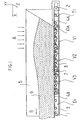
- a belt conveyor according to the invention shown in fig. 1 compacting comminuted/loose tobacco material comprises a tension roller 2 (not shown) placed in a tensioning portion T1 , and a driving roller 1 placed in a driving portion D1 with a mounted thereto external drive (not shown), a load-bearing structure in form of a vibratory sub-assembly, and a transporting belt 3 , transporting a material fed in portion A .
- the surface of the transporting belt may be smooth or may be profiled, depending on technological requirements.
- the vibratory sub-assembly has form of three separate vibratory portions V1 , V2 , V3, each of them comprising three rollers 10a equipped with eccentric elements 10b and symmetrically arranged counterweights 10c , and in case of using identical eccentric elements 10b on rollers 10a of all vibratory portions V1 , V2 , V3 , the distance between the transporting belt 3 and the axis of the rollers 10a of the first vibration portion V1 , corresponding to a starting portion, in which feeding of the loose tobacco material takes place, is minimal, the distances from the transporting belt 3 to the axes of rollers 10a of the successive vibratory portions V2 , V3 are increasing functions, and when axes of rollers 10a of all vibratory portions V1 , V2 , V3 are at the same distance from the transporting belt 3 then the active radius of eccentric elements 10b of the first vibratory portion V1 is biggest and the radius decreases for eccentric elements 10b of rollers 10a of successive vibratory portions V2 , V
- Each of the vibratory portions V1 , V2 , V3 has separate adjusting elements (not shown) providing independent adjustment of intensity and direction of a vector of the vibration amplitude, and has also separate adjusting elements providing independent adjustment of frequency of the transporting belt 3 oscillations, irrespective of the belt transporting rate.
- the adjusting elements adjust the distance and, optionally, inclination of each vibratory portion V1 , V2 , V3 relative to transporting belt 3 , while rollers 10a of each vibratory portion V1 , V2 , V3 are connected through pulleys 11 with separate driving arrangements, the driving arrangements being separate relative to the driving arrangement which drives the transporting belt 3 , driving arrangements (not shown) of the vibratory portions V1 , V2 , V3 are equipped with adjusting elements adjusting rotation rate of motors forming part of these driving arrangements.
- An additional belt conveyor 12 is fastened to the side walls 5 over the transporting belt 3 , the belt conveyor 12 comprising vibratory portions as shown in fig. 5 or a pressure plate (not shown) comprising vibratory portions is mounted swingingly on pins protruding from the side walls 5 over the transporting belt 3 .
- a stationary or rotary scraper bucket 13 may be attached to the side walls 5 over the ending portion of the transporting belt 3 , the scraper bucket 13 being equipped with adjusting elements for adjusting the height of the scraper bucket 13 relative to the surface of the transporting belt 3 and for adjusting the position of the scraper bucket 13 along the horizontal axis X extending along the movement direction of the transporting belt 3 .
- the conveyor according to the invention may have a plurality of mechanical vibratory portions V1 ... Vn .
- the conveyor may have a plurality of mechanical vibratory portions V1 ... Vn .
- characteristic feature of the conveyor is that both amplitude as well as frequency of vibrations of each vibratory portion are chosen, adjusted, and controlled irrespective of motion parameters of the transporting belt 3, including its linear speed.
- Rotation of eccentric rollers 10a in each vibratory portion V1 , V2 , V3 is synchronized via pulleys 11 with a toothed belt, not shown in the drawing. It means that the rotation of the rollers 10a , the rotation generating an amplitude of vibrations, is synchronized in each portion and may be controlled for example by a separate driving arrangement with a separate motor, irrespectively of motion parameters of the transporting belt 3.
- Such a solution allows for full control of vibratory movement of each roller 10a and in each of the vibratory portions V1 , V2 , V3 irrespectively of controlling all motion parameters of the transporting belt 3 .
- the upper profile of the transporting belt 3 may be chosen and adjusted according to the technological process requirements by suitable regulation and/or applying some elements generating vibrations of required profile.
- the upper surface of the transporting belt 3 may be inclined at a slight angle relatively to the horizontal direction, however it may be positioned horizontally, as in the presented solution.
- FIG. 1 Side walls 5 are placed on both sides of the belt conveyor shown in fig. 1, the side walls profiling stream of the transported material and precluding spillage of the material outside the conveyor.
- Fig. 2 presents how the side walls 5 are positioned relative to the belt conveyor.
- the profiling side walls 5 are fastened to the supporting frame 9a - 9e by means of brackets 5a .
- the belt conveyor according to the invention has a various, optimal for a given process, number of vibratory portions V1 ... Vn and and/or a number of kinds thereof, the vibratory portions generating vibrations of the transporting belt 3 .
- Three identical vibratory portions V1 , V2 , V3 occur in the presented embodiment, as shown in fig. 2.
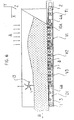
- Fig. 3 shows a view of a single module of a vibratory portion.
- the presented solution supporting frame 9a - 9e of the vibratory sub-assembly comprising vibratory portions form supporting side plates 9c with transverse stiffeners 7 , 8 which serve also as supports for moving transporting belt 3 .
- low-friction liners 4c are attached to the upper surfaces of the stiffeners 7 , 8 . Because of operational reasons, the low-friction liners applied in the tensioning portion T1 and the driving portion D1 have form of plates 4a and 4b , as shown in fig. 1.
- Rollers 10a are installed in the supporting frame 9a - 9e, eccentric elements 10b and symmetrically arranged counterweights 10c being assembled with the rollers 10a , the eccentric elements generating desired vibrations of the transporting belt 3 .
- Mounting the rollers 10a in bearings arranged in the supporting frame 9a - 9e allows them to rotate as a result of which vibrations of the transporting belt 3 are generated, the belt being tossed up by rotating eccentric elements 10b .
- Position of each vibratory portion V1 , V2 , and V3 relatively to the transporting belt 3 is adjusted by means of adjusting elements such that direction and magnitude of a vector of maximal vibration amplitude can be set according to a decreasing function, optimal for a given process.
- a position of any vibratory portion V1 , V2, and V3 may be changed along the axis X - Y - Z (fig. 1) and, moreover, each of the vibratory portions V1 , V2 , V3 may be inclined at an angle relative to the transporting belt 3 .
- each vibratory portion V1 , V2 , V3 has its own, separate driving arrangement. It is also possible that the transporting belt 3 as well as individual vibratory portions V1 , V2 , and V3 are driven by a single motor through transmission gear arrangements.
- amplitude and frequency of vibrations in each of the vibratory portions V1 , V2 , V3 may be adjusted and controlled within a given range, irrespective of values set in other portions.
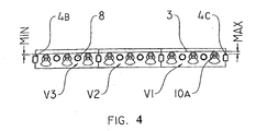
- the amplitude of vibrations of the transporting belt 3 of the conveyor is biggest in the starting portion of the conveyor, in which feeding of the material takes place, and is a characteristic function for a given process, and decreases in successive portions, i.e., amplitude of the first vibratory portion V1 is maximal whereas amplitude of the last vibratory portion V3 is minimal for a given series of vibratory portions, this being a result of employing the smallest distance between the first vibratory portion V1 and the transporting belt 3 and the longest distance between the third vibratory portion V3 and the transporting belt 3 when identical eccentric elements 10b are used or else employing a maximal active radius of eccentric elements 10b in the first vibratory portion V1 and a minimal active radius of eccentric elements 10b in the third vibratory portion V3 when identical distance of axes of the rollers 10
- Fig. 4 shows an arrangement of eccentric elements and distribution of vibration amplitude of the transporting belt 3 surface where the maximal vibration amplitude of the upper surface of the transporting belt 3 is achieved in the portion V1 while the minimal in portion V3.
- side walls 5 in form of a forming/sealing channel are placed adjacently along the length of the transporting belt 3 , preferably beyond the transporting belt 3 , as shown in fig. 1.
- the side walls 5 extend from the tension roller 2 at least to the driving roller 1 , with a possibility of extending beyond the tension roller 2 , in order to allow for correct, continuous transfer of the formed and compacted material stream to a successive machine and to avoid any disturbance of the stream of the tobacco particles at the discharge point.
- an additional belt conveyor 12 with vibratory portions, mounted within the side walls 5 , as shown in fig. 5.
- the purpose of this additional upper belt conveyor 12 is to intensify and/or facilitate compaction of the transported material.
- the purpose may be also to intensify and/or facilitate a uniform or any desired distribution of the transported material across the transporting belt 3 .
- the upper belt conveyor 12 may be replaced by a pressure plate having vibratory portions and mounted swingingly on pins protruding from the side walls 5 .
- the purpose of the plate is vibratory pressing down the transported material thereby compacting or facilitating compaction and/or distributing the material transported on the transporting belt 3 .
- the belt conveyor according to the invention with a stationary or rotary scraper bucket 13 , as shown in fig. 6, placed in the ending portion of the transporting belt 3 .
- the scraper bucket 13 may be installed on the side walls 5 , irrespective of the additional belt conveyor 12 or the pressure plate.
- the scraper bucket is equipped with adjusting elements (not shown) for adjusting its height relatively to the belt surface and for adjusting its position along the horizontal axis X .
- Employing the scraper bucket 13 makes it possible to obtain a constant level of the transported material at the output of the conveyor, irrespective of - fluctuations of feeding the material onto the conveyor.
Landscapes
- Engineering & Computer Science (AREA)
- Mechanical Engineering (AREA)
- Structure Of Belt Conveyors (AREA)
- Jigging Conveyors (AREA)
- Manufacture Of Tobacco Products (AREA)
- Manufacturing Of Cigar And Cigarette Tobacco (AREA)
- Rollers For Roller Conveyors For Transfer (AREA)
- Belt Conveyors (AREA)
Applications Claiming Priority (3)
| Application Number | Priority Date | Filing Date | Title |
|---|---|---|---|
| PL353387A PL205600B1 (pl) | 2002-04-12 | 2002-04-12 | Taśmowy przenośnik, transportujący rozdrobniony materiał tytoniowy |
| PL35338702 | 2002-04-12 | ||
| PCT/PL2003/000008 WO2003086114A1 (en) | 2002-04-12 | 2003-01-31 | Belt conveyor for transporting tobacco materials |
Publications (2)
| Publication Number | Publication Date |
|---|---|
| EP1494550A1 EP1494550A1 (en) | 2005-01-12 |
| EP1494550B1 true EP1494550B1 (en) | 2005-09-14 |
Family
ID=29245103
Family Applications (1)
| Application Number | Title | Priority Date | Filing Date |
|---|---|---|---|
| EP03746509A Expired - Lifetime EP1494550B1 (en) | 2002-04-12 | 2003-01-31 | Belt conveyor for transporting tobacco materials |
Country Status (12)
| Country | Link |
|---|---|
| US (1) | US6991092B2 (zh) |
| EP (1) | EP1494550B1 (zh) |
| JP (1) | JP4286668B2 (zh) |
| CN (1) | CN1313040C (zh) |
| AT (1) | ATE304299T1 (zh) |
| AU (1) | AU2003215974A1 (zh) |
| CA (1) | CA2480211C (zh) |
| DE (1) | DE60301621T2 (zh) |
| ES (1) | ES2249727T3 (zh) |
| PL (1) | PL205600B1 (zh) |
| RU (1) | RU2301005C2 (zh) |
| WO (1) | WO2003086114A1 (zh) |
Families Citing this family (16)
| Publication number | Priority date | Publication date | Assignee | Title |
|---|---|---|---|---|
| AU2003300045A1 (en) | 2002-12-31 | 2004-07-29 | Shuttleworth, Inc. | Compression passing roller |
| PL378835A1 (pl) * | 2006-01-27 | 2007-08-06 | International Tobacco Machinery Poland Spółka Z Ograniczoną Odpowiedzialnością | Sposób i urządzenie do uzyskania ciągłości jednorodności struktury i gęstości strumienia transportowanego luźnego produktu, zwłaszcza roślinnego, a zwłaszcza tytoniu |
| US7775343B2 (en) * | 2007-03-01 | 2010-08-17 | Key Technology, Inc. | Manufacturing device for use with a vibratory conveyor, and method for manufacturing a product |
| DE102012101024A1 (de) | 2012-02-08 | 2013-08-08 | Hauni Maschinenbau Ag | Vorrichtung und Verfahren zum Bilden mindestens eines Strangs der Tabak verarbeitenden Industrie sowie Verteilervorrichtung zum Beschicken einer Strangmaschine |
| ITUD20120056A1 (it) * | 2012-04-04 | 2013-10-05 | Danieli Off Mecc | Dispositivo di vibrazione per un'attrezzatura di convogliamento di una carica metallica in un impianto di fusione |
| CA3051120C (en) | 2015-07-03 | 2021-11-23 | George D. Dumbaugh | Vibrating screening feeder and method of use |
| CN107272605A (zh) * | 2016-04-07 | 2017-10-20 | 红塔烟草(集团)有限责任公司 | 制丝车间用储柜出料智能控制系统 |
| US11215397B2 (en) | 2017-07-17 | 2022-01-04 | The University Of Newcastle | Vibration unit assembly for a belt conveyor |
| CN107673091A (zh) * | 2017-09-25 | 2018-02-09 | 北新建材(嘉兴)有限公司 | 一种应用于熟石膏生产的松料装置 |
| KR101975399B1 (ko) * | 2018-04-27 | 2019-05-07 | 허인순 | 컨베이어벨트 이송장치 |
| CN108657747A (zh) * | 2018-07-06 | 2018-10-16 | 山东鼎泰盛食品工业装备股份有限公司 | 整理输送装置、整理输送机构及清洗装置 |
| CN108906494A (zh) * | 2018-09-11 | 2018-11-30 | 河南金拇指防水科技股份有限公司 | 多方位振动的防水材料成型装置 |
| CN110385742A (zh) * | 2019-06-28 | 2019-10-29 | 广东晶科电子股份有限公司 | 一种led剥料装置 |
| CN115917655A (zh) * | 2020-06-17 | 2023-04-04 | 美商亚威科技有限责任公司 | 使用超声破坏谷物和干制食品上的空气传播的病原体和微生物 |
| CN112794098B (zh) * | 2020-12-13 | 2024-09-17 | 云南昆船烟草设备有限公司 | 烟草薄片生产线松散物料投料的工艺系统及方法 |
| CN113558268B (zh) * | 2021-08-24 | 2022-12-16 | 龙岩烟草工业有限责任公司 | 物料储柜、储柜喂料机以及烟草加工设备 |
Family Cites Families (8)
| Publication number | Priority date | Publication date | Assignee | Title |
|---|---|---|---|---|
| US1992361A (en) * | 1933-03-15 | 1935-02-26 | Diescher Tube Mills Inc | Cooling rack |
| NL44038C (zh) * | 1935-09-07 | |||
| DE8331379U1 (de) | 1983-11-02 | 1985-04-11 | Hauni-Werke Körber & Co KG, 2050 Hamburg | Vorrichtung zum bilden einer homogenen schicht aus fasern von tabak |
| US4911827A (en) | 1988-06-02 | 1990-03-27 | Danny L. Ryan | Grass seed cleaner |
| US5762176A (en) * | 1996-11-08 | 1998-06-09 | Fmc Corporation | Belt driven vibratory apparatus |
| US6269940B1 (en) * | 1999-04-27 | 2001-08-07 | Carrier Vibrating Equipment, Inc. | Reversing conveying brute force vibratory feeder |
| US6851548B1 (en) * | 1999-07-30 | 2005-02-08 | Kinergy Corporation | Vibratory conveying apparatus adapted to be driven by a plurality of accumulatively phased pairs of rotating eccentric weights |
| US6276518B1 (en) * | 1999-08-30 | 2001-08-21 | Key Technology, Inc. | Vibratory drive for a vibratory conveyor |
-
2002
- 2002-04-12 PL PL353387A patent/PL205600B1/pl unknown
-
2003
- 2003-01-31 AU AU2003215974A patent/AU2003215974A1/en not_active Abandoned
- 2003-01-31 JP JP2003583146A patent/JP4286668B2/ja not_active Expired - Fee Related
- 2003-01-31 DE DE60301621T patent/DE60301621T2/de not_active Expired - Lifetime
- 2003-01-31 US US10/508,811 patent/US6991092B2/en not_active Expired - Fee Related
- 2003-01-31 EP EP03746509A patent/EP1494550B1/en not_active Expired - Lifetime
- 2003-01-31 RU RU2004132712/12A patent/RU2301005C2/ru not_active IP Right Cessation
- 2003-01-31 ES ES03746509T patent/ES2249727T3/es not_active Expired - Lifetime
- 2003-01-31 CA CA002480211A patent/CA2480211C/en not_active Expired - Fee Related
- 2003-01-31 WO PCT/PL2003/000008 patent/WO2003086114A1/en active IP Right Grant
- 2003-01-31 CN CNB038081695A patent/CN1313040C/zh not_active Expired - Fee Related
- 2003-01-31 AT AT03746509T patent/ATE304299T1/de not_active IP Right Cessation
Also Published As
| Publication number | Publication date |
|---|---|
| CA2480211A1 (en) | 2003-10-23 |
| US20050167247A1 (en) | 2005-08-04 |
| RU2004132712A (ru) | 2005-05-27 |
| CA2480211C (en) | 2007-02-13 |
| JP4286668B2 (ja) | 2009-07-01 |
| RU2301005C2 (ru) | 2007-06-20 |
| AU2003215974A1 (en) | 2003-10-27 |
| US6991092B2 (en) | 2006-01-31 |
| EP1494550A1 (en) | 2005-01-12 |
| PL205600B1 (pl) | 2010-05-31 |
| PL353387A1 (en) | 2003-10-20 |
| DE60301621D1 (de) | 2005-10-20 |
| ATE304299T1 (de) | 2005-09-15 |
| DE60301621T2 (de) | 2006-07-13 |
| JP2005522205A (ja) | 2005-07-28 |
| CN1646034A (zh) | 2005-07-27 |
| CN1313040C (zh) | 2007-05-02 |
| WO2003086114A1 (en) | 2003-10-23 |
| ES2249727T3 (es) | 2006-04-01 |
Similar Documents
| Publication | Publication Date | Title |
|---|---|---|
| EP1494550B1 (en) | Belt conveyor for transporting tobacco materials | |
| US4457840A (en) | Apparatus for delivering a stream of green pellets | |
| CA2116349C (en) | Process for continuously forming a uniform layer of loose material and installation for carrying out the process | |
| US4163489A (en) | Feeder apparatus for fibrous materials | |
| US3227263A (en) | Vibratory regulation of an endless conveying device | |
| US20050035155A1 (en) | Dispersion system for dispersing material especially wood chips wood-fibre or similar on a dispersing conveyor belt | |
| CA2174474C (en) | Vibratory apparatus | |
| CN1195399A (zh) | 将散装料输入回转床炉的方法和设备 | |
| US5297316A (en) | Apparatus for producing fiber material or the like with a precise feed weight | |
| US4744714A (en) | Bin vibrating discharge device for surge or blending bins or the like | |
| CA1078238A (en) | Plate vibrator | |
| US3622018A (en) | Apparatus for providing mass flow of stored material | |
| US4793787A (en) | Apparatus for the production of mat webs from a mixture of granules | |
| CH650651A5 (it) | Macchina confezionatrice di sigarette con unita ausiliaria di alimentazione di tabacco. | |
| CN201106987Y (zh) | 用于转底炉回转台的进料与布料装置 | |
| JPS6151862B2 (zh) | ||
| US5238374A (en) | Apparatus for controlling density profile in a concrete extruded slab | |
| CN109353761A (zh) | 一种可调式振动给料器 | |
| CN221274396U (zh) | 一种振动喂料器计量装置 | |
| JP2007314269A (ja) | 回転式物品均し装置 | |
| JPH0354400Y2 (zh) | ||
| US4517988A (en) | Feeding tobacco cutting machines | |
| SU1344693A1 (ru) | Питатель сыпучих кормов | |
| JPS6313891B2 (zh) | ||
| FI84574C (fi) | Inmatningsanordning foer en spridare. |
Legal Events
| Date | Code | Title | Description |
|---|---|---|---|
| PUAI | Public reference made under article 153(3) epc to a published international application that has entered the european phase |
Free format text: ORIGINAL CODE: 0009012 |
|
| 17P | Request for examination filed |
Effective date: 20041020 |
|
| AK | Designated contracting states |
Kind code of ref document: A1 Designated state(s): AT BE BG CH CY CZ DE DK EE ES FI FR GB GR HU IE IT LI LU MC NL PT SE SI SK TR |
|
| AX | Request for extension of the european patent |
Extension state: AL LT LV MK RO |
|
| GRAP | Despatch of communication of intention to grant a patent |
Free format text: ORIGINAL CODE: EPIDOSNIGR1 |
|
| GRAS | Grant fee paid |
Free format text: ORIGINAL CODE: EPIDOSNIGR3 |
|
| GRAA | (expected) grant |
Free format text: ORIGINAL CODE: 0009210 |
|
| AK | Designated contracting states |
Kind code of ref document: B1 Designated state(s): AT BE BG CH CY CZ DE DK EE ES FI FR GB GR HU IE IT LI LU MC NL PT SE SI SK TR |
|
| PG25 | Lapsed in a contracting state [announced via postgrant information from national office to epo] |
Ref country code: SI Free format text: LAPSE BECAUSE OF FAILURE TO SUBMIT A TRANSLATION OF THE DESCRIPTION OR TO PAY THE FEE WITHIN THE PRESCRIBED TIME-LIMIT Effective date: 20050914 Ref country code: SK Free format text: LAPSE BECAUSE OF FAILURE TO SUBMIT A TRANSLATION OF THE DESCRIPTION OR TO PAY THE FEE WITHIN THE PRESCRIBED TIME-LIMIT Effective date: 20050914 Ref country code: BE Free format text: LAPSE BECAUSE OF FAILURE TO SUBMIT A TRANSLATION OF THE DESCRIPTION OR TO PAY THE FEE WITHIN THE PRESCRIBED TIME-LIMIT Effective date: 20050914 Ref country code: CZ Free format text: LAPSE BECAUSE OF FAILURE TO SUBMIT A TRANSLATION OF THE DESCRIPTION OR TO PAY THE FEE WITHIN THE PRESCRIBED TIME-LIMIT Effective date: 20050914 Ref country code: FI Free format text: LAPSE BECAUSE OF FAILURE TO SUBMIT A TRANSLATION OF THE DESCRIPTION OR TO PAY THE FEE WITHIN THE PRESCRIBED TIME-LIMIT Effective date: 20050914 |
|
| REG | Reference to a national code |
Ref country code: GB Ref legal event code: FG4D |
|
| REG | Reference to a national code |
Ref country code: CH Ref legal event code: EP |
|
| REG | Reference to a national code |
Ref country code: IE Ref legal event code: FG4D |
|
| REF | Corresponds to: |
Ref document number: 60301621 Country of ref document: DE Date of ref document: 20051020 Kind code of ref document: P |
|
| PG25 | Lapsed in a contracting state [announced via postgrant information from national office to epo] |
Ref country code: SE Free format text: LAPSE BECAUSE OF FAILURE TO SUBMIT A TRANSLATION OF THE DESCRIPTION OR TO PAY THE FEE WITHIN THE PRESCRIBED TIME-LIMIT Effective date: 20051214 Ref country code: DK Free format text: LAPSE BECAUSE OF FAILURE TO SUBMIT A TRANSLATION OF THE DESCRIPTION OR TO PAY THE FEE WITHIN THE PRESCRIBED TIME-LIMIT Effective date: 20051214 Ref country code: BG Free format text: LAPSE BECAUSE OF FAILURE TO SUBMIT A TRANSLATION OF THE DESCRIPTION OR TO PAY THE FEE WITHIN THE PRESCRIBED TIME-LIMIT Effective date: 20051214 Ref country code: GR Free format text: LAPSE BECAUSE OF FAILURE TO SUBMIT A TRANSLATION OF THE DESCRIPTION OR TO PAY THE FEE WITHIN THE PRESCRIBED TIME-LIMIT Effective date: 20051214 |
|
| REG | Reference to a national code |
Ref country code: CH Ref legal event code: NV Representative=s name: E. BLUM & CO. PATENTANWAELTE |
|
| PGFP | Annual fee paid to national office [announced via postgrant information from national office to epo] |
Ref country code: AT Payment date: 20060126 Year of fee payment: 4 |
|
| PG25 | Lapsed in a contracting state [announced via postgrant information from national office to epo] |
Ref country code: LU Free format text: LAPSE BECAUSE OF NON-PAYMENT OF DUE FEES Effective date: 20060131 Ref country code: IE Free format text: LAPSE BECAUSE OF NON-PAYMENT OF DUE FEES Effective date: 20060131 Ref country code: MC Free format text: LAPSE BECAUSE OF NON-PAYMENT OF DUE FEES Effective date: 20060131 |
|
| PG25 | Lapsed in a contracting state [announced via postgrant information from national office to epo] |
Ref country code: PT Free format text: LAPSE BECAUSE OF FAILURE TO SUBMIT A TRANSLATION OF THE DESCRIPTION OR TO PAY THE FEE WITHIN THE PRESCRIBED TIME-LIMIT Effective date: 20060214 |
|
| PGFP | Annual fee paid to national office [announced via postgrant information from national office to epo] |
Ref country code: ES Payment date: 20060224 Year of fee payment: 4 |
|
| REG | Reference to a national code |
Ref country code: HU Ref legal event code: AG4A Ref document number: E000167 Country of ref document: HU |
|
| REG | Reference to a national code |
Ref country code: ES Ref legal event code: FG2A Ref document number: 2249727 Country of ref document: ES Kind code of ref document: T3 |
|
| ET | Fr: translation filed | ||
| PLBE | No opposition filed within time limit |
Free format text: ORIGINAL CODE: 0009261 |
|
| STAA | Information on the status of an ep patent application or granted ep patent |
Free format text: STATUS: NO OPPOSITION FILED WITHIN TIME LIMIT |
|
| 26N | No opposition filed |
Effective date: 20060615 |
|
| REG | Reference to a national code |
Ref country code: IE Ref legal event code: MM4A |
|
| PGFP | Annual fee paid to national office [announced via postgrant information from national office to epo] |
Ref country code: CH Payment date: 20061206 Year of fee payment: 5 |
|
| PGFP | Annual fee paid to national office [announced via postgrant information from national office to epo] |
Ref country code: NL Payment date: 20070131 Year of fee payment: 5 |
|
| REG | Reference to a national code |
Ref country code: CH Ref legal event code: PFA Owner name: INTERNATIONAL TOBACCO MACHINERY POLAND LTD Free format text: INTERNATIONAL TOBACCO MACHINERY POLAND LTD#UL. WARSZTATOWA 19A, P.O. BOX 113#26 600 RADOM (PL) -TRANSFER TO- INTERNATIONAL TOBACCO MACHINERY POLAND LTD#UL. WARSZTATOWA 19A, P.O. BOX 113#26 600 RADOM (PL) |
|
| PG25 | Lapsed in a contracting state [announced via postgrant information from national office to epo] |
Ref country code: AT Free format text: LAPSE BECAUSE OF NON-PAYMENT OF DUE FEES Effective date: 20070131 |
|
| REG | Reference to a national code |
Ref country code: ES Ref legal event code: FD2A Effective date: 20070201 |
|
| PG25 | Lapsed in a contracting state [announced via postgrant information from national office to epo] |
Ref country code: EE Free format text: LAPSE BECAUSE OF FAILURE TO SUBMIT A TRANSLATION OF THE DESCRIPTION OR TO PAY THE FEE WITHIN THE PRESCRIBED TIME-LIMIT Effective date: 20050914 |
|
| PG25 | Lapsed in a contracting state [announced via postgrant information from national office to epo] |
Ref country code: ES Free format text: LAPSE BECAUSE OF NON-PAYMENT OF DUE FEES Effective date: 20070201 Ref country code: TR Free format text: LAPSE BECAUSE OF FAILURE TO SUBMIT A TRANSLATION OF THE DESCRIPTION OR TO PAY THE FEE WITHIN THE PRESCRIBED TIME-LIMIT Effective date: 20050914 |
|
| REG | Reference to a national code |
Ref country code: CH Ref legal event code: PL |
|
| NLV4 | Nl: lapsed or anulled due to non-payment of the annual fee |
Effective date: 20080801 |
|
| PG25 | Lapsed in a contracting state [announced via postgrant information from national office to epo] |
Ref country code: NL Free format text: LAPSE BECAUSE OF NON-PAYMENT OF DUE FEES Effective date: 20080801 Ref country code: CH Free format text: LAPSE BECAUSE OF NON-PAYMENT OF DUE FEES Effective date: 20080131 Ref country code: LI Free format text: LAPSE BECAUSE OF NON-PAYMENT OF DUE FEES Effective date: 20080131 |
|
| PG25 | Lapsed in a contracting state [announced via postgrant information from national office to epo] |
Ref country code: CY Free format text: LAPSE BECAUSE OF FAILURE TO SUBMIT A TRANSLATION OF THE DESCRIPTION OR TO PAY THE FEE WITHIN THE PRESCRIBED TIME-LIMIT Effective date: 20050914 |
|
| PGFP | Annual fee paid to national office [announced via postgrant information from national office to epo] |
Ref country code: DE Payment date: 20140122 Year of fee payment: 12 |
|
| PGFP | Annual fee paid to national office [announced via postgrant information from national office to epo] |
Ref country code: HU Payment date: 20140121 Year of fee payment: 12 Ref country code: FR Payment date: 20140123 Year of fee payment: 12 Ref country code: IT Payment date: 20140128 Year of fee payment: 12 |
|
| PGFP | Annual fee paid to national office [announced via postgrant information from national office to epo] |
Ref country code: GB Payment date: 20140121 Year of fee payment: 12 |
|
| REG | Reference to a national code |
Ref country code: DE Ref legal event code: R119 Ref document number: 60301621 Country of ref document: DE |
|
| GBPC | Gb: european patent ceased through non-payment of renewal fee |
Effective date: 20150131 |
|
| PG25 | Lapsed in a contracting state [announced via postgrant information from national office to epo] |
Ref country code: DE Free format text: LAPSE BECAUSE OF NON-PAYMENT OF DUE FEES Effective date: 20150801 Ref country code: GB Free format text: LAPSE BECAUSE OF NON-PAYMENT OF DUE FEES Effective date: 20150131 |
|
| REG | Reference to a national code |
Ref country code: FR Ref legal event code: ST Effective date: 20150930 |
|
| PG25 | Lapsed in a contracting state [announced via postgrant information from national office to epo] |
Ref country code: FR Free format text: LAPSE BECAUSE OF NON-PAYMENT OF DUE FEES Effective date: 20150202 Ref country code: HU Free format text: LAPSE BECAUSE OF NON-PAYMENT OF DUE FEES Effective date: 20150201 |
|
| PG25 | Lapsed in a contracting state [announced via postgrant information from national office to epo] |
Ref country code: IT Free format text: LAPSE BECAUSE OF NON-PAYMENT OF DUE FEES Effective date: 20150131 |