EP1493875A2 - Méthode et dispositif de rénovation des regards d'eaux usées - Google Patents
Méthode et dispositif de rénovation des regards d'eaux usées Download PDFInfo
- Publication number
- EP1493875A2 EP1493875A2 EP04008214A EP04008214A EP1493875A2 EP 1493875 A2 EP1493875 A2 EP 1493875A2 EP 04008214 A EP04008214 A EP 04008214A EP 04008214 A EP04008214 A EP 04008214A EP 1493875 A2 EP1493875 A2 EP 1493875A2
- Authority
- EP
- European Patent Office
- Prior art keywords
- shaft
- lining
- hand
- channel
- plastic
- Prior art date
- Legal status (The legal status is an assumption and is not a legal conclusion. Google has not performed a legal analysis and makes no representation as to the accuracy of the status listed.)
- Withdrawn
Links
Images


Classifications
-
- E—FIXED CONSTRUCTIONS
- E03—WATER SUPPLY; SEWERAGE
- E03F—SEWERS; CESSPOOLS
- E03F5/00—Sewerage structures
- E03F5/02—Manhole shafts or other inspection chambers; Snow-filling openings; accessories
-
- E—FIXED CONSTRUCTIONS
- E03—WATER SUPPLY; SEWERAGE
- E03F—SEWERS; CESSPOOLS
- E03F3/00—Sewer pipe-line systems
- E03F3/06—Methods of, or installations for, laying sewer pipes
-
- E—FIXED CONSTRUCTIONS
- E03—WATER SUPPLY; SEWERAGE
- E03F—SEWERS; CESSPOOLS
- E03F3/00—Sewer pipe-line systems
- E03F3/06—Methods of, or installations for, laying sewer pipes
- E03F2003/065—Refurbishing of sewer pipes, e.g. by coating, lining
Definitions
- the invention relates to a method for refurbishing a Shaft with a shaft lining made of plastic.
- the invention relates to a device for rehabilitation a pit in which at least one sewer opens, with a plastic shaft lining.
- the object of the present invention is therefore a method and to provide a device by means of which a more appropriate Installation of manhole liners is made possible.
- This object is achieved in terms of the method thereby that the mine with respect to at least one sewer is adjusted and the manhole lining re through the pit extending portion of the sewer aligned and connected to it.
- the Sewer in the area of the pit formed as a channel and the manhole lining is relative to the gutter aligned and connected to it.
- the Pit plant with one sewer each via a gutter section connected.
- the gutter sections were at their abutting Ends connected to a gutter and the manhole lining is aligned with respect to the gutter and connected to it.
- the installation of the gutter is much easier, without that thereby the static strength of the entire manhole lining would suffer.
- a further preferred embodiment of the invention is formed in the area of the pit as a groove Sewer with its tubular ends through holes led, which is limited by a pit plant Shaft wall in the direction of the sewers extend, and on surfaces of the tubular ends Sealing elements are attached, which are waterproof with the Schachtausconstru and the performances are connected. Also by the connection of these Abêtlememente with the channel Care is taken that these sealing elements of their Task can be justice, the interior of the mine permanently sealed against the surrounding soil.
- On The base of the gutter will be the individual building elements that become from the gigs, the sealing elements and the shaft lining put together so interconnected that they have one To form a fixed unit that makes up individual elements even with occurring external loads of the mine can not solve.
- the gigs and the sealing elements as a plastic sheet trained, on the one hand with the gutter and the other with the shaft lining are connected.
- These plastic sheets On the one hand, they are comparatively cheap in terms of purchase as well as in the processing. They can be simple Welded together and form together a waterproof unit.
- plastic sheets in the form of two in the longitudinal direction formed extending partial webs are the plastic sheets in the form of two in the longitudinal direction formed extending partial webs, the one given Include angle between them. This also shows the advantage to use plastic sheets, as these the respective Demand can be deformed accordingly.
- one of the two partial webs extends in an approximately horizontal Level while the other sub-web is about vertical to this level runs.
- This design suits you especially well if necessary, because the horizontal surface as appearance good is suitable and the adjoining vertical surface represents a spatial connection to the surface of the channel, with which it is welded. In this way, the Appearance as a sure stand for one within the Schachtstrom acting becoming specialist to be designed.
- both the levels are approximately horizontal Partial webs of performances on the one hand and the sealing elements on the other hand, as well as in vertical planes are partial webs the performances on the one hand and sealing elements on the other waterproof connected. Also through this connection largely similarly designed parts comes a solid and rigid construction of the entire floor construction, through the shaft lining permanently inside the pit can be aligned. The construction is not only waterproof but also firmly against the gutter aligned and thus against detachments and shifts secured within the mine.
- a further preferred embodiment of the invention becomes an existing below the horizontally extending partial webs Cavity bordering a bottom of the mine is filled with a hardening mass. In this way is provided for a filling of the cavity, so that in that no vermin can nest. In addition, by the Filling the cavity with a hardening mass, that the entire lower part of the chess lining a maintains high static strength and forms a unit that can withstand very large loads.
- the plastic sheets are used to training the performances made of a circular plastic plate whose cross section corresponds to that of the mine in the area of the channel, the circular plastic plate along one Diameter line divided into two semicircular part plates and each of the sub-panels along a parallel to Diameter line running sector line so angled that arise perpendicular to plastic plate extending faces, of which one each on both sides of the channel connected to this becomes.
- the assembly of performances within the shaft once again greatly simplified.
- the interiors of the mine are ready standardized that of a standard cross section in the range the gutter can be assumed.
- This standard cross section the circular plate is adapted so that a prefabrication the performances to be used is possible.
- a substantial deformation of the circular partial plate can no longer take place, but can be delivered in the form immediately inside the interior of the shaft to be built in.
- a further preferred embodiment of the invention has an appearance on its surface anti-slip processing on. In this way, even before installation of the Plate ensured that the rising into the pit Specialist finds a firm hold on the performances. A Editing the performance must be done on the spot no longer take place.
- a fitting ring with the manhole lining connected is the appearance of a fitting ring with the manhole lining connected.
- the use of this fitting ring has the big one Advantage that a very extensive exact adaptation in area the transition from the appearance of the shaft linings take place can.
- the construction is also very stable and resistant to deformation, so that even when using relatively small wall thicknesses for Production of plastic sheets with a high strength the overall construction can be expected.
- a plastic existing manhole lining is expediently the Sewer in the area of the mine formed as a channel, with at least one tubular end extends through a hole in a limiting the pit Shaft wall is provided.
- the gutter provided as the basis for alignment of the manhole lining.
- the manhole lining receives a very dimensionally stable base, since the gutter on the one hand by their immediate connection with the sewer a solid foundation forms for the manhole lining and on the other hand the Shaft with respect to the gutter in which through the Schachtwandung extending hole is firmly guided. On this It is impossible that the pit opposite the Rinne performs proper movements.
- the gutter gigs provided on the one hand with a surface the gutter and on the other hand with the manhole lining are firmly connected.
- the performances stiffen the mine opposite the gutter, so that overall a very dimensionally stable and built against bending rigid structure.
- the appearances are as partial webs running at an angle to each other formed, one of which is approximately vertical Partial track connected to a surface of the channel waterproof is and an approximately horizontally extending partial path with her the vertically extending part of the web remote surface the manhole lining is watertight connected in one predetermined distance is arranged to shaft wall.
- a further preferred embodiment of the invention are at the junctions of the tubular ends in the Shaft wall sealing elements provided on the one hand an approximately horizontally extending partial web of a plastic plate which is waterproof with the manhole lining connected, and on the other hand from one of the horizontal extending sub-orbit down angled approximately vertical Partial track, with the lower edge remote from the horizontal part track the gutter is firmly connected.
- This will be a high Waterproof also in the area of the manhole lining and the shaft wall penetrates penetrating holes and in addition in the area of these holes a security against deformation created the shaft lining. In this way also arises in the area of the pipe ends of the gutter receiving Holes a rigidity of the manhole lining and in addition a security against water leaks.
- the shaft lining a high water resistance generated and the rigidity of the entire floor construction elevated.
- the channel consists of two sections, both with their associated tubular ends by a respective hole of the Shaft wall in a sewer associated with this hole protrude, and the two sections are with their successive zu doden ends connected to each other.
- the cuts can easily fit into them associated sewers introduced and waterproof with these get connected.
- they put together connected sections is a rigid construction, which in the sewers are exactly guided and after their connection the mine safely together in their initial position lead and driving up this pit, for example Exclude due to high water pressure.
- the device is designed as a mounting set, the a shaft lining and two sections of the Gutter, the appearance and the sealing of which after insertion and connection of the gutter sections on this way resulting gutter connected with the two performances and then the seals on the one hand with the gutter and on the other hand with the performances and finally the manhole lining in the mine on the performances on the one hand and the seals on the other aligned and connected via pass rings with these become.
- a very reliable waterproof Connection of the performances in the area of the shaft lining This is also very durable and stiffening with connected to the performances.
- the performances consist of a circular plastic plate, whose cross section corresponds to that of the mine in the amount of corresponds to the mounted gutter limiting upper edge and along a diameter line in two semicircular Sub-plates is divided, and each sub-plate along one parallel to the diameter line extending sector line in two is subdivided into mutually perpendicular sub-areas of those of the diameter line adjacent narrower and with a surface of the gutter is connectable while the wider toward a shaft lining to be provided Shaft conversion of the shaft protrudes and with the shaft lining is connectable.
- a fitting ring on the one hand with the performance and on the other hand with the Manhole lining is firmly connected.
- This pass ring poses a very convenient installation relief that is suitable is quick, and waterproof, the individual parts of the mounting kit to connect with each other.
- a further preferred embodiment of the invention is a below the mounted performances to the ground of the shaft formed cavity of a curing Mass refillable. This stiffened additionally the appearances and provides a firm connection to the bottom of the mine.
- the manhole lining consists of an unfoldable infinite Plastic sheet, which after its unfolding to neighboring Has shaft walls at a distance of about 5 - 20 mm. These Training the shaft wall facilitates their introduction into the pits and an exact alignment with respect to Shaft wall. The stiffening of the shaft lining takes place on the one hand by the connection with the performances and on the other hand by a support against the shaft wall.
- the shaft lining is facing the shaft wall Outside provided with anchors, for example as nubs in one between the outside of the shaft wall intervene insertable hardening mass.
- anchors for example as nubs in one between the outside of the shaft wall intervene insertable hardening mass.
- a steel fabric covering this attached to which the shaft lining is connected is at the shaft wall a steel fabric covering this attached to which the shaft lining is connected.
- the manhole lining for boarding the mine trained projections provided as by the Manhole lining through dowels secured in the shaft wall are formed, which sheathed with a plastic layer are. These projections facilitate entry into the Pit. They are rigidly connected to the shaft wall and protrude through the manhole lining.
- the Waterproofness is made by having a Plastic layer are jacketed, which in turn with the Manhole lining is connected watertight.
- the dowel protrudes with a screw in the end of the shaft lining enclosed interior of the mine, and on the screw is an end provided with an internal thread Bolt screwed as a step, with a Plastic layer is surrounded with the manhole lining waterproof is connectable. This makes the projection easy mountable and resistant to deformation. Its waterproof Connection with the manhole lining is guaranteed.
- the mine at its opposite the ground upper end provided with an elastic joint, which is over the shaft wall, the shaft lining and the insulating material extends, in the space between the shaft wall and the manhole lining is arranged.
- This elastic Grout prevents moisture from entering Upper edges of the shaft wall, the shaft lining and the consisting of insulating material intermediate layer.
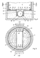
- a shaft system (2) embedded in a road surface (1) consists essentially of a shaft wall (3) and a Shaft bottom (4).
- the shaft wall (3) surrounds an interior space (5) facing towards the road surface (1) of a Opening (6) is completed.
- On the shaft wall (3) is in the direction of the interior (5) a steel fabric (7) attached.
- a dowel (8) into it protrudes into the shaft wall (3) a dowel (8) into it.
- the shaft wall (3) is usually made of masonry Stones or concrete. In any case, it can be assumed that that the shaft wall (3) is open-pored, so that approximately on an outer side (12) of the shaft wall (3) accumulating groundwater through the shaft wall (3) can get into the distance (9). This can be in the Distance (9) form a water column, which is suitable, the Manhole lining (10) in the direction of the interior (5) deform. To prevent such deformation, the Shaft lining (10) connected to the shaft wall (3), for example by means of the dowel (8) or by an attachment on steel mesh (7).
- the shaft lining (10) consists of a water-impermeable Plastic, for example polyethylene. These Manhole lining (10) is in the form of a deformable plastic web into the interior (5) brought in and then with respect the shaft wall (3) aligned so that between the manhole lining (10) and the shaft wall (3) over the entire height of the mine (2) and over its entire length Cross section of the distance (9) is about the same size.
- the pit (2) are in the shaft wall (3) holes (14), (15) provided, through which a channel (16) with their raw-shaped ends (17), (18) in the direction of sewers (19), (20).
- the raw-shaped ends (17), (18) are designed in this way, that they are in one of the sewer (19), (20) enclosed Interior (21), (22) can protrude and opposite this sealed by means of seals (23), (24), (25) are.
- These three seals (23), (24), (25) lie in Longitudinal direction of the channel (16) on its raw-shaped ends (17), (18) in a row.
- the gutter (16) consists of two gutter sections (28), (29). Each of these two sections (28), (29) protrudes with the respective tubular ends (17), (18) in the respectively adjacent Sewer (19), (20) into it. This will be the gutter sections (28), (29) aligned so that they are with each other collide adjacent ends (39), (31) in the interior (5). In this position, the two ends (30), (31) connected by a weld (32).
- the channel (16) is supported with one each Collar (33), (34) on the surface (11) of the shaft wall (3) from. In this way, the channel (16) is immovable within of the interior (5).
- the performances (35), (36) with the Sealing elements (52), (53) a firmly interconnected Surface created by joining with the help of welds (58), (59) form a watertight unit. Furthermore is on this of the performances (35), (36) AND the sealing elements (52), (53) also formed the manhole lining (10) firmly connected by means of the fitting ring (46). Thus form the manhole liners (10) together with the Performances (35), (36) and the sealing elements (52), (53) a waterproof unit, which is a leak of sewage the mine (2) and an intrusion of groundwater into excludes the interior (5). As far as water in the interior (5) collects, this is on the groove (16) towards the sewer (19), (20) transported away.
- barbs (66) may be provided, the a particularly intense connection between the performances (35), (36) and the sealing elements (52), (53) on the one hand and on the other hand cause the mortar (63).
- a similar education is also on a the interior (5) facing away back (67) of the manhole lining (10).
- bumps (65) are provided with barbs (66), which are with connect a mortar (63) filled in the distance (9). This also causes a stiffening of the entire system.
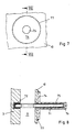
- Projections (70) can be fastened on the shaft lining (10) be, which protrude into the interior (5) and to serve, a specialist, not shown, the entry into to allow the interior (5).
- Bolt (71) via a dowel (72) in the shaft wall (3) attached.
- the bolt (71) protrudes through a corresponding Hole provided in the manhole lining (10) is, in the interior (5) inside.
- This consists essentially of a plate-shaped Plate (74) on which a tubular projection (75) is provided.
- This tubular projection (75) has a Inner cross section (76), which screwed onto the bolt (71) can be.
- the tubular projection (75) is fixed connected to the plate-shaped plate (74), in turn with a weld (77) with the manhole lining (10) connected is. This prevents being in the area of the bolt (71) water either from the interior (5) in the distance (9) or from these into the interior (5) can penetrate.
- a set is initially from gutter sections (28), (29), two appearances (35), (36), two sealing elements (52), (53) delivered. After removal possibly still existing gutter remains one now become useless gutter the two gutter pieces (28), (29) in the holes (14), (15) and thus in the sewers (19), (20). Then the two gutter sections (28), (29) in the region of their ends (30), (31) connected by the weld (32).
- the manhole lining (10) can still with the help of a Dowels (8) or with the help of steel fabric (7) on the shaft wall (3) are attached.
- the elastic Groove (69) provided in the region of the upper end (68), to seal the upper ends (68). Then you can the provided with a manhole cover, not shown Schacht be handed back to traffic.
Landscapes
- Health & Medical Sciences (AREA)
- Life Sciences & Earth Sciences (AREA)
- Engineering & Computer Science (AREA)
- Hydrology & Water Resources (AREA)
- Public Health (AREA)
- Water Supply & Treatment (AREA)
- Sewage (AREA)
- Lining Or Joining Of Plastics Or The Like (AREA)
Applications Claiming Priority (2)
| Application Number | Priority Date | Filing Date | Title |
|---|---|---|---|
| DE2003115559 DE10315559A1 (de) | 2003-04-05 | 2003-04-05 | Verfahren und Vorrichtung zum Sanieren einer Schachtanlage |
| DE10315559 | 2003-04-05 |
Publications (2)
| Publication Number | Publication Date |
|---|---|
| EP1493875A2 true EP1493875A2 (fr) | 2005-01-05 |
| EP1493875A3 EP1493875A3 (fr) | 2006-11-08 |
Family
ID=33426668
Family Applications (1)
| Application Number | Title | Priority Date | Filing Date |
|---|---|---|---|
| EP04008214A Withdrawn EP1493875A3 (fr) | 2003-04-05 | 2004-04-05 | Méthode et dispositif de rénovation des regards d'eaux usées |
Country Status (2)
| Country | Link |
|---|---|
| EP (1) | EP1493875A3 (fr) |
| DE (1) | DE10315559A1 (fr) |
Cited By (5)
| Publication number | Priority date | Publication date | Assignee | Title |
|---|---|---|---|---|
| DK178948B1 (da) * | 2016-03-14 | 2017-06-26 | Ermo Glasfiber Aps | Foringsanordning |
| CN112610270A (zh) * | 2020-12-04 | 2021-04-06 | 中煤第七十一工程处有限责任公司 | 一种新型矿用风井出矸施工系统 |
| CN118007780A (zh) * | 2024-04-10 | 2024-05-10 | 水利部交通运输部国家能源局南京水利科学研究院 | 一种深层隧道和竖井联合导气止爆结构及方法 |
| EP4431664A1 (fr) * | 2023-03-14 | 2024-09-18 | REHAU Industries SE & Co. KG | Agencement de puits |
| EP4431663A1 (fr) * | 2023-03-14 | 2024-09-18 | REHAU Industries SE & Co. KG | Agencement de puits |
Citations (3)
| Publication number | Priority date | Publication date | Assignee | Title |
|---|---|---|---|---|
| DE19834317A1 (de) * | 1997-08-28 | 1999-03-25 | Walter Jens | Verfahren zur Sanierung der Sohle von Abwässerschächten |
| DE10129860A1 (de) * | 2001-06-21 | 2003-01-16 | Yvonne Spitzenberg | Schachtbodenauskleidung zur Erstellung eines Kanalisationsschachtbodens |
| EP1391565A2 (fr) * | 2002-05-08 | 2004-02-25 | Wolfgang Schwarz | Procédé et dispositif pour connecter une membrane plastique imperméable et une conduite |
Family Cites Families (8)
| Publication number | Priority date | Publication date | Assignee | Title |
|---|---|---|---|---|
| DE2509909C3 (de) * | 1975-03-07 | 1978-11-09 | Andreas 8201 Kolbermoor Weiss | Verfahren zum Herstellen einer Rinnensohle in einem Revisionsschacht und Platte zum Durchführen des Verfahrens |
| DE3028093C2 (de) * | 1980-07-24 | 1982-11-18 | Schneider Gmbh & Co, 5020 Frechen | Bausatz zur Erstellung eines Kanalisationsschacht-Gerinnes mit Auftritt |
| DE3032179A1 (de) * | 1980-08-27 | 1982-04-22 | Karl 4783 Anröchte Broermann | Saeurefestes unterteil fuer einen abwasser-kontrollschacht |
| DE8629215U1 (de) * | 1986-11-03 | 1987-01-08 | ACO Severin Ahlmann GmbH & Co KG, 2370 Rendsburg | Schachtbauwerk |
| DE29612834U1 (de) * | 1996-07-24 | 1996-09-12 | Kunststoffröhren Sendenhorst GmbH, 48324 Sendenhorst | Betonfertigteil-Schacht mit einer Kunststoff-Auskleidung |
| DE29711337U1 (de) * | 1997-06-20 | 1997-09-04 | Betonwerk Burgwedel GmbH, 30938 Burgwedel | Auskleidung aus Kunststoff für Schachtunterteile |
| DE29712099U1 (de) * | 1997-07-09 | 1997-10-23 | Koser, Wolfgang, Dr., 67269 Grünstadt | Auskleidung für Kanalschächte |
| DE29802823U1 (de) * | 1998-02-18 | 1998-04-09 | Kerschbaum, Lutz, Dipl.-Ing., Eberschwang | Vorgefertigter Schacht |
-
2003
- 2003-04-05 DE DE2003115559 patent/DE10315559A1/de not_active Ceased
-
2004
- 2004-04-05 EP EP04008214A patent/EP1493875A3/fr not_active Withdrawn
Patent Citations (3)
| Publication number | Priority date | Publication date | Assignee | Title |
|---|---|---|---|---|
| DE19834317A1 (de) * | 1997-08-28 | 1999-03-25 | Walter Jens | Verfahren zur Sanierung der Sohle von Abwässerschächten |
| DE10129860A1 (de) * | 2001-06-21 | 2003-01-16 | Yvonne Spitzenberg | Schachtbodenauskleidung zur Erstellung eines Kanalisationsschachtbodens |
| EP1391565A2 (fr) * | 2002-05-08 | 2004-02-25 | Wolfgang Schwarz | Procédé et dispositif pour connecter une membrane plastique imperméable et une conduite |
Cited By (5)
| Publication number | Priority date | Publication date | Assignee | Title |
|---|---|---|---|---|
| DK178948B1 (da) * | 2016-03-14 | 2017-06-26 | Ermo Glasfiber Aps | Foringsanordning |
| CN112610270A (zh) * | 2020-12-04 | 2021-04-06 | 中煤第七十一工程处有限责任公司 | 一种新型矿用风井出矸施工系统 |
| EP4431664A1 (fr) * | 2023-03-14 | 2024-09-18 | REHAU Industries SE & Co. KG | Agencement de puits |
| EP4431663A1 (fr) * | 2023-03-14 | 2024-09-18 | REHAU Industries SE & Co. KG | Agencement de puits |
| CN118007780A (zh) * | 2024-04-10 | 2024-05-10 | 水利部交通运输部国家能源局南京水利科学研究院 | 一种深层隧道和竖井联合导气止爆结构及方法 |
Also Published As
| Publication number | Publication date |
|---|---|
| EP1493875A3 (fr) | 2006-11-08 |
| DE10315559A1 (de) | 2004-12-30 |
Similar Documents
| Publication | Publication Date | Title |
|---|---|---|
| EP3521557B1 (fr) | Cadre multifonction pour constructions tubulaires | |
| DE9109954U1 (de) | Bausystem für einen ebenerdigen Entwässerungsgraben | |
| EP1493875A2 (fr) | Méthode et dispositif de rénovation des regards d'eaux usées | |
| EP2320001A2 (fr) | Dispositif d'établissement d'un coffrage partiel et/ou d'un coffrage à joint de dilatation sur une construction en béton | |
| DE102005005861A1 (de) | Verbindungs- und Modulsystem zur Erstellung von druckwasserfesten Bauwerken aus Betonfertigteilen | |
| DE4345415C2 (de) | Montagegrube mit doppelwandiger Stahlkassette | |
| DE20013774U1 (de) | Baumodul zum Herstellen von Brücken, Gebäuden und Türmen, z.B. für Windkraftanlagen | |
| DE29721919U1 (de) | Flüssigkeitsbehälter, insbesondere Schwimmbecken, Silobehälter oder Güllegrube und Konstruktionsmodul hierfür | |
| DE102009058691A1 (de) | Thermisch isolierende Gebäudewand | |
| DE2710429A1 (de) | Betonbauwerk mit einem innenraum, insbesondere kanalisationsrohr | |
| EP3176330B1 (fr) | Couverture d'un support | |
| DE3714664C2 (fr) | ||
| DE3302075A1 (de) | Spannbeton- oder stahlbetonbiegetraeger | |
| DE2336041A1 (de) | Fertighaus | |
| EP1632613B1 (fr) | Cave pour des bâtiments | |
| DE3926867C2 (fr) | ||
| DE19503345C1 (de) | Vorrichtung zur Belüftung und Entwässerung von abgelagerten Materialien | |
| DE19618003C2 (de) | Vorsatzbalkon | |
| EP1082503B1 (fr) | Faux-plancher | |
| DE20316487U1 (de) | Bauanordnung für eine Überlaufrinne eines Schwimmbeckenrands | |
| DE4011736A1 (de) | Verfahren zur herstellung von schaechten | |
| DE20309107U1 (de) | Abdichtelement für die Herstellung wasserundurchlässiger Außenwände bei Beton-Doppelwandelementen | |
| AT407540B (de) | Fassade für ein gebäude mit stehern | |
| DE4343851C1 (de) | Ortbetonschlitzwand mit Abdichtungsmembran | |
| WO1990002089A1 (fr) | Garniture d'etancheite pour ouvrages d'art et procede pour sa fabrication |
Legal Events
| Date | Code | Title | Description |
|---|---|---|---|
| PUAI | Public reference made under article 153(3) epc to a published international application that has entered the european phase |
Free format text: ORIGINAL CODE: 0009012 |
|
| AK | Designated contracting states |
Kind code of ref document: A2 Designated state(s): AT BE BG CH CY CZ DE DK EE ES FI FR GB GR HU IE IT LI LU MC NL PL PT RO SE SI SK TR |
|
| AX | Request for extension of the european patent |
Extension state: AL HR LT LV MK |
|
| PUAL | Search report despatched |
Free format text: ORIGINAL CODE: 0009013 |
|
| AK | Designated contracting states |
Kind code of ref document: A3 Designated state(s): AT BE BG CH CY CZ DE DK EE ES FI FR GB GR HU IE IT LI LU MC NL PL PT RO SE SI SK TR |
|
| AX | Request for extension of the european patent |
Extension state: AL HR LT LV MK |
|
| 17P | Request for examination filed |
Effective date: 20070508 |
|
| AKX | Designation fees paid |
Designated state(s): AT BE BG CH CY CZ DE DK EE ES FI FR GB GR HU IE IT LI LU MC NL PL PT RO SE SI SK TR |
|
| 17Q | First examination report despatched |
Effective date: 20080331 |
|
| STAA | Information on the status of an ep patent application or granted ep patent |
Free format text: STATUS: THE APPLICATION IS DEEMED TO BE WITHDRAWN |
|
| 18D | Application deemed to be withdrawn |
Effective date: 20100306 |