EP1493873B1 - Ablaufventil mit Servomotor - Google Patents
Ablaufventil mit Servomotor Download PDFInfo
- Publication number
- EP1493873B1 EP1493873B1 EP04014560A EP04014560A EP1493873B1 EP 1493873 B1 EP1493873 B1 EP 1493873B1 EP 04014560 A EP04014560 A EP 04014560A EP 04014560 A EP04014560 A EP 04014560A EP 1493873 B1 EP1493873 B1 EP 1493873B1
- Authority
- EP
- European Patent Office
- Prior art keywords
- outlet valve
- sanitary device
- servomotor
- sanitary
- drain valve
- Prior art date
- Legal status (The legal status is an assumption and is not a legal conclusion. Google has not performed a legal analysis and makes no representation as to the accuracy of the status listed.)
- Expired - Lifetime
Links
Images

Classifications
-
- E—FIXED CONSTRUCTIONS
- E03—WATER SUPPLY; SEWERAGE
- E03D—WATER-CLOSETS OR URINALS WITH FLUSHING DEVICES; FLUSHING VALVES THEREFOR
- E03D1/00—Water flushing devices with cisterns ; Setting up a range of flushing devices or water-closets; Combinations of several flushing devices
- E03D1/02—High-level flushing systems
- E03D1/22—Twin or multiple flushing cisterns
-
- E—FIXED CONSTRUCTIONS
- E03—WATER SUPPLY; SEWERAGE
- E03D—WATER-CLOSETS OR URINALS WITH FLUSHING DEVICES; FLUSHING VALVES THEREFOR
- E03D1/00—Water flushing devices with cisterns ; Setting up a range of flushing devices or water-closets; Combinations of several flushing devices
- E03D1/02—High-level flushing systems
- E03D1/14—Cisterns discharging variable quantities of water also cisterns with bell siphons in combination with flushing valves
- E03D1/142—Cisterns discharging variable quantities of water also cisterns with bell siphons in combination with flushing valves in cisterns with flushing valves
-
- E—FIXED CONSTRUCTIONS
- E03—WATER SUPPLY; SEWERAGE
- E03D—WATER-CLOSETS OR URINALS WITH FLUSHING DEVICES; FLUSHING VALVES THEREFOR
- E03D5/00—Special constructions of flushing devices, e.g. closed flushing system
- E03D5/12—Special constructions of flushing devices, e.g. closed flushing system discharging periodically
-
- E—FIXED CONSTRUCTIONS
- E03—WATER SUPPLY; SEWERAGE
- E03D—WATER-CLOSETS OR URINALS WITH FLUSHING DEVICES; FLUSHING VALVES THEREFOR
- E03D9/00—Sanitary or other accessories for lavatories ; Devices for cleaning or disinfecting the toilet room or the toilet bowl; Devices for eliminating smells
- E03D9/02—Devices adding a disinfecting, deodorising, or cleaning agent to the water while flushing
-
- E—FIXED CONSTRUCTIONS
- E03—WATER SUPPLY; SEWERAGE
- E03D—WATER-CLOSETS OR URINALS WITH FLUSHING DEVICES; FLUSHING VALVES THEREFOR
- E03D9/00—Sanitary or other accessories for lavatories ; Devices for cleaning or disinfecting the toilet room or the toilet bowl; Devices for eliminating smells
- E03D9/04—Special arrangement or operation of ventilating devices
-
- E—FIXED CONSTRUCTIONS
- E03—WATER SUPPLY; SEWERAGE
- E03D—WATER-CLOSETS OR URINALS WITH FLUSHING DEVICES; FLUSHING VALVES THEREFOR
- E03D1/00—Water flushing devices with cisterns ; Setting up a range of flushing devices or water-closets; Combinations of several flushing devices
- E03D1/02—High-level flushing systems
- E03D1/14—Cisterns discharging variable quantities of water also cisterns with bell siphons in combination with flushing valves
- E03D2001/147—Cisterns discharging variable quantities of water also cisterns with bell siphons in combination with flushing valves having provisions for active interruption of flushing
Definitions
- the invention relates to a sanitary device with a arranged in a toilet cistern discharge valve and an electrically operated actuator for opening the drain valve.
- Simple drain valves for cisterns consist of a valve closure element which cooperates with a arranged in the bottom of the cistern valve seat.
- the opening is effected by an actuating force acting directly on the closure element, which is transmitted to the closure element by means of a pull rod or chain.
- the valve closure element is designed as an overflow pipe, wherein the valve seat at the drain opening in the bottom of the cistern cooperates with an annular flange on the overflow pipe to close the drain valve.
- the entire overflow pipe is raised. Once the drain valve exceeds a certain opening position, the static pressure of the water column causes an automatic, complete opening of the valve, wherein the overflow pipe is held during the flushing by a float in the open position.
- the overflow pipe sinks together with the water level in the cistern until the ring flange rests on the valve seat on the overflow pipe and shuts off the drain valve.
- the overflow pipe sinks together with the water level in the cistern until the ring flange rests on the valve seat on the overflow pipe and shuts off the drain valve.
- an electronically controlled operating device for a drain valve which additionally controls a discharge of a chemical cleaning agent in the water rinse.
- JP 2002 315693 A a control unit for the electronic control of a plurality of functions in a bathroom, including a controllable cleaning device arranged in a toilet.
- the invention has for its object to provide a sanitary device of the type mentioned, which goes beyond the previous technical concepts.
- the actuating device comprises a servo motor, and the servo motor for opening and closing the drain valve is connected to the drain valve by means of a forced coupling.
- a further embodiment of the invention provides that the drain valve comprises aphobiaetaufrohr and the servomotor is connected to the overflow pipe of the drain valve.
- the servomotor can be mounted so as to be storable relative to the overflow pipe.
- the positive coupling to compensate for the bearing mounting of the servomotor mounted fixed at least with a first connection point on the servo motor and at least one further connection point on the overflow pipe be.
- an adjustment of the forced coupling is adjustable to different constructions of toilet cisterns and different positions of the servomotor on a mounting device above the maximum possible water level.
- smooth operation of the drain valve is ensured despite different constructions and positions.
- the positive coupling has a lockable in several layers locking mechanism.
- This locking mechanism allows the adjustment of the forced coupling to the individual mounting situation and mounting deviations in the individual toilet cisterns. Also, the effect of the servomotor on the drain valve can be changed by this lockable in several layers latching mechanism.
- Such locking mechanisms can be realized in the form of racks or juxtaposed locking elements or locking lugs, which can be locked in many positions.
- At least one connecting element may be provided at the at least one further connection point, which surrounds the overflow pipe on its outer circumference.
- the connecting element does not completely enclose the outer circumference, but only to the extent that a secure connection to the overflow pipe is formed.
- An expedient embodiment of the sanitary device according to the invention provides that intermediate positions between an open end position and a closed end position of the drain valve can be approached via the servomotor. By means of such intermediate positions, smaller flushing volumes adapted to a lower flushing requirement can be realized during a flushing operation, e.g. with only liquid entry into the toilet bowl or to moisten the toilet bowl. Also can be set by intermediate positions of the drain valve, a lesser volume flow of the rinse water and thereby realize an extension or adaptation of the flushing to the particular circumstances.
- the servomotor can be connected to a programmable and storing program control, and by the program control the opening and closing of the drain valve, as well as the position of the drain valve and the Dwell time be controlled in this position.
- the program control controls the opening and closing of the drain valve, as well as the position of the drain valve and the Dwell time be controlled in this position.
- time-dependent intermediate rinses can be programmed and executed.
- the programmable program control also allows special rinsing procedures, which allow for a better flushing success, in spite of a lower water input, such as stuttering or interval rinsing.
- the sanitary device may comprise a, in particular in the toilet cistern arranged, detergent unit, via the toilet cistern and / or the drain valve, a detergent can be supplied.
- the program control can control the supply of the cleaning agent.
- a further control unit for the detergent supply is superfluous.
- a variant of the sanitary device according to the invention provides that the program control in a defined flushing operation controls the opening and closing, the position and dwell time of the drain valve and the supply of the cleaning agent coordinated with each other.
- the flushing process adapted in this way to the requirements of the application case and the selected flushing process allows a good cleaning effect through the coordinated introduction of the cleaning agent.
- a further embodiment provides that at least one additional function in the sanitary area, in particular an emergency call function, the lighting or a ventilation, is controlled by an operating unit of the drain valve.
- an emergency call function the lighting or a ventilation
- the combination of different functions in the sanitary area increases the comfort for the user and offers relief especially for the disabled or the elderly.
- the control unit buttons for operating the light, a fan, an odor extraction, an ionizer and other functions include.
- the operating unit can transmit the control signals to the actuating device by a radio device.
- This allows a free positioning of the control unit regardless of the arrangement of the toilet cistern. Furthermore, no cabling is necessary by the radio transmission of the control signals, whereby the retrofitting of existing sanitary facilities is considerably simplified.
- the invention relates to the use of a servomotor for actuating an actuator for opening and closing a drain valve of an electrically operated sanitary lavage, wherein the servomotor is connected to the drain valve by a positive coupling.
- the use is characterized by the fact that a servo motor is used for the electrically operated sanitary flushing, through which the drain valve can be precisely controlled at any time via the forced coupling. Also, the forced coupling of the drain valve to the servomotor allows fast, active opening and closing movements.
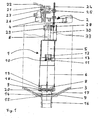
- the sanitary device according to the invention in Fig. 1 has a drain valve 1 with an actuator 2.
- the drain valve 1 is arranged in the bottom region of the Spippokastengeophuses 3.
- the actuating device 2 is attached to a traverse 4 in the upper region of the Spülkastengephaseuses 3.
- the drain valve 1 consists of an upper housing part 5, a lower housing part 6, a sealing element 7 and an overflow pipe 8.
- the sealing element 7 is arranged in the lower part of the Spippokastengepuruses 3 and connected via webs 9 with the lower housing part 6.
- the lower housing part 6 and the upper housing part 5 are connected to one another via a latching element 10.
- the locking element 10 is made from a latching lug 11 on the lower housing part 6 and a flap 12 formed in the upper housing part 5, which has a latching opening 13 for engagement with the latching lug 11.
- the overflow pipe 8 is movably arranged in the upper housing part 5 and the lower housing part 6, wherein it has an area lying above the upper housing part 5 and extends through the upper housing part 5 and the lower housing part 6 to the sealing element 7.
- the sealing element 7 has at its directed to the Spippokastengephaseuse 3 part of a cistern seal 14, which seals the cistern together with the stop shoulder 15 in the connection piece 16 of the Spülkastengephases 3 downwards.
- the cistern housing 3 is located in the lower area on a Spülkastenhalterung 17, which has a recess in the region of the connecting piece 16.
- the standing with the sealing member 7 in communication lower part of the overflow pipe 8 has an outer guide ring 18 which is guided between the webs 9, wherein the lateral clearance of the lower part of the overflow pipe 8 is limited by the small clearance to the guide ring 18.
- the drain valve 1 has between the webs 9 openings 19 for the passage of the rinse water, which are bounded above by the lower housing part 6 and downwards from the sealing element 7. Between the overflow pipe 8 and the sealing element 7, an overflow pipe seal 20 is provided, which prevents a drainage of the rinsing water through the openings 19 and the sealing element 7 in the connecting piece 16 in the closed state.
- the actuating device 2 consists of a servomotor 21, which can be addressed via a connection line 22 and a lever arm 23 arranged on the servomotor, which transmits the movement of the servomotor 21 to a latching rod 24.
- the locking rod 24 has a round in cross-section shape with arranged at regular intervals over the length of the locking rod 24 cross-sectional constrictions.
- the locking rod 24 is connected via the locking element 25 with the upper portion of the lever arm 23.
- the latching region of the locking element 25 is designed as a cylinder slotted on both sides, wherein the slotted areas engage in the cross-sectional constrictions of the locking rod 24.
- the servomotor 21 is disposed on a mounting base 26 which is mounted on a mounting bar 4, which is connected to the Spülkastengeophuse 3 or a cover of the Spülkastengeophuses.
- a lateral actuating pin 28 is arranged, which engages in a connecting element 29 which is arranged at the upper end of the overflow pipe 8.
- the lower end of the locking rod 24 with the side Actuating pin 28 is guided in a protective sleeve 30, which has a slot to the overflow pipe 8, through which the lateral actuating pin 28 can engage in the connecting element 29.
- the servomotor 21 may be connected via the connecting line 22 to an optional program control not shown in the figures.
- the program control can be arranged directly on the servo motor 21 or at any position in the cistern or outside the cistern.
- a control of the program control can be done by an operating unit not shown in detail, which optionally transmits the control signals by a radio device to the program control.
- Fig. 2 In addition to the overflow pipe seal 20 and the cooperating with this seal sealing surface 31 can be seen at the bottom of the overflow pipe 8.
- the lower end of the overflow pipe 8 below the sealing surface 31 is matched in its shape to the inner contour of the sealing element 7. This area closes off towards the sealing element 7 with a further seal 32, which prevents the flushing water from flowing out of the flushing cistern when the drain valve is closed as a further seal.
- the cistern seal 14 arranged on the sealing element 7 of the drain valve 1 seals the cistern to the connecting piece 16, so that the flushing water can only reach the connecting piece 16 via the openings 19 and the sealing element 7 provided with an opening in the interior.
- the overflow pipe seal 20 closes on the sealing element 7 in conjunction with the sealing surface 31 on the overflow pipe 8 and the seal 32 of the overflow pipe 8, the passage in the sealing element 7.
- the flushing water can not get into the connecting piece 16 in this closed end state.
- the cistern is filled with rinse water and the waterline 33 is at a high level just below the top of the overflow tube 8.
- the servo motor 21 moves the locking rod 24 and connected to the locking rod overflow pipe 8 down.
- the overflow pipe seal 20 and the seal 32 on the overflow pipe 8 are pressed onto their sealing surfaces and close the passage in the sealing element 7.
- the inflow of rinse water to the connecting piece 16 is thereby interrupted.
- the water level 33 rises again in the cistern.
Landscapes
- Health & Medical Sciences (AREA)
- Public Health (AREA)
- Engineering & Computer Science (AREA)
- Life Sciences & Earth Sciences (AREA)
- Hydrology & Water Resources (AREA)
- Water Supply & Treatment (AREA)
- Epidemiology (AREA)
- Aviation & Aerospace Engineering (AREA)
- Electrically Driven Valve-Operating Means (AREA)
- Sanitary Device For Flush Toilet (AREA)
- Toys (AREA)
- Multiple-Way Valves (AREA)
Priority Applications (1)
| Application Number | Priority Date | Filing Date | Title |
|---|---|---|---|
| PL04014560T PL1493873T3 (pl) | 2003-07-04 | 2004-06-22 | Zawór odpływowy z serwosilnikiem |
Applications Claiming Priority (2)
| Application Number | Priority Date | Filing Date | Title |
|---|---|---|---|
| DE10330324 | 2003-07-04 | ||
| DE10330324A DE10330324A1 (de) | 2003-07-04 | 2003-07-04 | Ablaufventil mit Servomotor |
Publications (3)
| Publication Number | Publication Date |
|---|---|
| EP1493873A2 EP1493873A2 (de) | 2005-01-05 |
| EP1493873A3 EP1493873A3 (de) | 2006-04-26 |
| EP1493873B1 true EP1493873B1 (de) | 2008-08-06 |
Family
ID=33426873
Family Applications (1)
| Application Number | Title | Priority Date | Filing Date |
|---|---|---|---|
| EP04014560A Expired - Lifetime EP1493873B1 (de) | 2003-07-04 | 2004-06-22 | Ablaufventil mit Servomotor |
Country Status (5)
| Country | Link |
|---|---|
| EP (1) | EP1493873B1 (pl) |
| AT (1) | ATE403785T1 (pl) |
| DE (2) | DE10330324A1 (pl) |
| DK (1) | DK1493873T3 (pl) |
| PL (1) | PL1493873T3 (pl) |
Families Citing this family (2)
| Publication number | Priority date | Publication date | Assignee | Title |
|---|---|---|---|---|
| CN102605844B (zh) * | 2012-04-11 | 2013-09-18 | 厦门瑞尔特卫浴科技股份有限公司 | 一种双档排水阀线控机构 |
| EP2660399B1 (de) | 2012-05-03 | 2014-08-20 | Geberit International AG | Betätigungsvorrichtung für ein Auslaufventil einer Spülvorrichtung |
Family Cites Families (15)
| Publication number | Priority date | Publication date | Assignee | Title |
|---|---|---|---|---|
| US4392260A (en) | 1982-07-06 | 1983-07-12 | Bensen Court M | Flushing apparatus with selective quantity control |
| US5003643A (en) * | 1989-11-14 | 1991-04-02 | Wilson Chung | Flush controller for a toilet bowl |
| US5036553A (en) * | 1990-06-26 | 1991-08-06 | Sanderson Dilworth D | Fully automatic toilet system |
| GB9310039D0 (en) * | 1993-05-15 | 1993-06-30 | Smiths Industries Plc | Water management and treatment systems |
| GB2302623A (en) * | 1995-06-24 | 1997-01-22 | Lukes Engineering Co Ltd | Electric motor drive device for operating a lever |
| IT1280896B1 (it) * | 1995-08-04 | 1998-02-11 | Plastic Investment Holding S A | Dispositivo pneumatico per l'azionamento di una valvola di scarico di una cassetta di risciacquo per wc |
| FR2740793B1 (fr) * | 1995-11-03 | 1998-01-30 | Wirquin Plastiques Sa | Dispositif de commande de vidage d'appareils sanitaires |
| DE19631078A1 (de) * | 1996-08-01 | 1998-02-05 | Siegfried Verl | Verfahren zur Reinigung von Toilettenbecken |
| FR2770547B1 (fr) * | 1997-11-03 | 2000-02-11 | Wirquin Plastiques Sa | Dispositif de commande electrique de chasse d'eau sanitaire permettant de deverser des quantites d'eau variables |
| NO314638B1 (no) * | 1998-12-17 | 2003-04-22 | Ido Bathroom Ltd | Anordning ved beröringsfri klosettspyler |
| DE20104033U1 (de) * | 2000-05-18 | 2001-06-21 | Geberit Technik Ag, Jona | Spülkasten für eine Klosettanlage |
| JP2002315693A (ja) * | 2001-04-20 | 2002-10-29 | Toto Ltd | トイレ設備 |
| DE20117432U1 (de) * | 2001-10-24 | 2002-01-24 | Georg Fischer Schwab GmbH & Co. KG, 72793 Pfullingen | Zweimengenspülvorrichtung |
| FR2835550B1 (fr) * | 2002-02-06 | 2006-12-01 | Wirquin Plastiques Sa | Dispositif de commande motorise pour mecanisme de chasse d'eau |
| DE10222193A1 (de) * | 2002-05-18 | 2003-11-27 | Thomas Wartmann | Elektronische Wasserspülung |
-
2003
- 2003-07-04 DE DE10330324A patent/DE10330324A1/de not_active Withdrawn
-
2004
- 2004-06-22 DK DK04014560T patent/DK1493873T3/da active
- 2004-06-22 PL PL04014560T patent/PL1493873T3/pl unknown
- 2004-06-22 EP EP04014560A patent/EP1493873B1/de not_active Expired - Lifetime
- 2004-06-22 DE DE502004007761T patent/DE502004007761D1/de not_active Expired - Lifetime
- 2004-06-22 AT AT04014560T patent/ATE403785T1/de not_active IP Right Cessation
Also Published As
| Publication number | Publication date |
|---|---|
| DE502004007761D1 (de) | 2008-09-18 |
| PL1493873T3 (pl) | 2009-01-30 |
| EP1493873A2 (de) | 2005-01-05 |
| ATE403785T1 (de) | 2008-08-15 |
| DK1493873T3 (da) | 2008-12-01 |
| EP1493873A3 (de) | 2006-04-26 |
| DE10330324A1 (de) | 2005-01-20 |
Similar Documents
| Publication | Publication Date | Title |
|---|---|---|
| EP2986787B1 (de) | Wc mit intimdusche, die im spülwasserverteiler integriert ist | |
| EP0915210B1 (de) | Ablaufventil für Spülkästen | |
| DE3153688C2 (pl) | ||
| EP1703027B1 (de) | Vorrichtung zur Betätigung des Ablaufventils von Sanitärartikeln und insbesondere einer Badewanne | |
| DE4241023C2 (de) | Vorrichtung zur Verhinderung oder Verminderung der durch Waschbecken, Spülbecken, Badewannen o. dgl. verursachten Keime | |
| EP3728747B1 (de) | Ventil | |
| WO2018104413A1 (de) | Druckwasserventil | |
| EP2322729B1 (de) | Ab- und Überlaufgarnitur, insbesondere für Badewannen | |
| EP1813732B1 (de) | Drehrosette zur Betätigung eines Ablaufventils einer Ab- und Überlaufgarnitur einer Badewanne | |
| DE2010111A1 (de) | Wasserklosett mit Entlüftungs- und Spülvorrichtung | |
| EP1493873B1 (de) | Ablaufventil mit Servomotor | |
| DE10002308C2 (de) | WC-Spülkasten | |
| DE3841911C2 (de) | Sanitärarmatur | |
| CH621378A5 (en) | Upwardly directed shower device for WCs | |
| DE29900260U1 (de) | Spüleinrichtung an einer eine Klosettschüssel aufweisenden Klosettanlage | |
| EP1842972A1 (de) | Sanitärarmatur mit versenkbarem Auslauf | |
| EP4187028B1 (de) | Filtereinrichtung für einen spülkasten und spülkasten für eine sanitäreinrichtung | |
| DE10300931A1 (de) | Vorrichtung zum Betätigen der Ablaufglocke eines WC-Spülkastens | |
| DE3153689C2 (de) | Schwimmerventil zur Steuerung des Wassereinlaufs in einem Toiletten-Spülkasten | |
| EP1388617B1 (de) | Ablaufgarnitur | |
| DE102007017377B4 (de) | Hydrant-Entleerungssystem | |
| DE4116320A1 (de) | Wasserkasten - fuell,- und ablassventil | |
| DE10248016B3 (de) | Stellorgan sowie dieses umfassender Ablöschkasten und Verfahren zur Regelung des Füllstands eines Flüssigkeitssammelbehälters | |
| DE3153738C2 (de) | Schwimmerventil zur Steuerung des Wassereinlaufs in einen Toiletten-Spülkasten | |
| EP0520267A1 (de) | Verfahren zum Steuern einer Hubeinrichtung und Hubeinrichtung für bewegungsbehinderte Menschen |
Legal Events
| Date | Code | Title | Description |
|---|---|---|---|
| PUAI | Public reference made under article 153(3) epc to a published international application that has entered the european phase |
Free format text: ORIGINAL CODE: 0009012 |
|
| AK | Designated contracting states |
Kind code of ref document: A2 Designated state(s): AT BE BG CH CY CZ DE DK EE ES FI FR GB GR HU IE IT LI LU MC NL PL PT RO SE SI SK TR |
|
| AX | Request for extension of the european patent |
Extension state: AL HR LT LV MK |
|
| PUAL | Search report despatched |
Free format text: ORIGINAL CODE: 0009013 |
|
| AK | Designated contracting states |
Kind code of ref document: A3 Designated state(s): AT BE BG CH CY CZ DE DK EE ES FI FR GB GR HU IE IT LI LU MC NL PL PT RO SE SI SK TR |
|
| AX | Request for extension of the european patent |
Extension state: AL HR LT LV MK |
|
| RAP1 | Party data changed (applicant data changed or rights of an application transferred) |
Owner name: GROHE AG |
|
| 17P | Request for examination filed |
Effective date: 20061018 |
|
| 17Q | First examination report despatched |
Effective date: 20061121 |
|
| AKX | Designation fees paid |
Designated state(s): AT BE BG CH CY CZ DE DK EE ES FI FR GB GR HU IE IT LI LU MC NL PL PT RO SE SI SK TR |
|
| GRAP | Despatch of communication of intention to grant a patent |
Free format text: ORIGINAL CODE: EPIDOSNIGR1 |
|
| GRAS | Grant fee paid |
Free format text: ORIGINAL CODE: EPIDOSNIGR3 |
|
| GRAA | (expected) grant |
Free format text: ORIGINAL CODE: 0009210 |
|
| AK | Designated contracting states |
Kind code of ref document: B1 Designated state(s): AT BE BG CH CY CZ DE DK EE ES FI FR GB GR HU IE IT LI LU MC NL PL PT RO SE SI SK TR |
|
| REG | Reference to a national code |
Ref country code: GB Ref legal event code: FG4D Free format text: NOT ENGLISH |
|
| REG | Reference to a national code |
Ref country code: CH Ref legal event code: EP |
|
| REG | Reference to a national code |
Ref country code: IE Ref legal event code: FG4D Free format text: LANGUAGE OF EP DOCUMENT: GERMAN |
|
| REF | Corresponds to: |
Ref document number: 502004007761 Country of ref document: DE Date of ref document: 20080918 Kind code of ref document: P |
|
| REG | Reference to a national code |
Ref country code: CH Ref legal event code: NV Representative=s name: BOVARD AG PATENTANWAELTE |
|
| REG | Reference to a national code |
Ref country code: SE Ref legal event code: TRGR |
|
| REG | Reference to a national code |
Ref country code: DK Ref legal event code: T3 |
|
| PG25 | Lapsed in a contracting state [announced via postgrant information from national office to epo] |
Ref country code: ES Free format text: LAPSE BECAUSE OF FAILURE TO SUBMIT A TRANSLATION OF THE DESCRIPTION OR TO PAY THE FEE WITHIN THE PRESCRIBED TIME-LIMIT Effective date: 20081117 |
|
| REG | Reference to a national code |
Ref country code: PL Ref legal event code: T3 |
|
| PG25 | Lapsed in a contracting state [announced via postgrant information from national office to epo] |
Ref country code: SI Free format text: LAPSE BECAUSE OF FAILURE TO SUBMIT A TRANSLATION OF THE DESCRIPTION OR TO PAY THE FEE WITHIN THE PRESCRIBED TIME-LIMIT Effective date: 20080806 Ref country code: FI Free format text: LAPSE BECAUSE OF FAILURE TO SUBMIT A TRANSLATION OF THE DESCRIPTION OR TO PAY THE FEE WITHIN THE PRESCRIBED TIME-LIMIT Effective date: 20080806 |
|
| REG | Reference to a national code |
Ref country code: IE Ref legal event code: FD4D |
|
| PG25 | Lapsed in a contracting state [announced via postgrant information from national office to epo] |
Ref country code: BG Free format text: LAPSE BECAUSE OF FAILURE TO SUBMIT A TRANSLATION OF THE DESCRIPTION OR TO PAY THE FEE WITHIN THE PRESCRIBED TIME-LIMIT Effective date: 20081106 Ref country code: IE Free format text: LAPSE BECAUSE OF FAILURE TO SUBMIT A TRANSLATION OF THE DESCRIPTION OR TO PAY THE FEE WITHIN THE PRESCRIBED TIME-LIMIT Effective date: 20080806 |
|
| PG25 | Lapsed in a contracting state [announced via postgrant information from national office to epo] |
Ref country code: SK Free format text: LAPSE BECAUSE OF FAILURE TO SUBMIT A TRANSLATION OF THE DESCRIPTION OR TO PAY THE FEE WITHIN THE PRESCRIBED TIME-LIMIT Effective date: 20080806 Ref country code: RO Free format text: LAPSE BECAUSE OF FAILURE TO SUBMIT A TRANSLATION OF THE DESCRIPTION OR TO PAY THE FEE WITHIN THE PRESCRIBED TIME-LIMIT Effective date: 20080806 Ref country code: PT Free format text: LAPSE BECAUSE OF FAILURE TO SUBMIT A TRANSLATION OF THE DESCRIPTION OR TO PAY THE FEE WITHIN THE PRESCRIBED TIME-LIMIT Effective date: 20090106 Ref country code: CZ Free format text: LAPSE BECAUSE OF FAILURE TO SUBMIT A TRANSLATION OF THE DESCRIPTION OR TO PAY THE FEE WITHIN THE PRESCRIBED TIME-LIMIT Effective date: 20080806 |
|
| PLBE | No opposition filed within time limit |
Free format text: ORIGINAL CODE: 0009261 |
|
| STAA | Information on the status of an ep patent application or granted ep patent |
Free format text: STATUS: NO OPPOSITION FILED WITHIN TIME LIMIT |
|
| 26N | No opposition filed |
Effective date: 20090507 |
|
| PG25 | Lapsed in a contracting state [announced via postgrant information from national office to epo] |
Ref country code: EE Free format text: LAPSE BECAUSE OF FAILURE TO SUBMIT A TRANSLATION OF THE DESCRIPTION OR TO PAY THE FEE WITHIN THE PRESCRIBED TIME-LIMIT Effective date: 20080806 |
|
| PG25 | Lapsed in a contracting state [announced via postgrant information from national office to epo] |
Ref country code: IT Free format text: LAPSE BECAUSE OF FAILURE TO SUBMIT A TRANSLATION OF THE DESCRIPTION OR TO PAY THE FEE WITHIN THE PRESCRIBED TIME-LIMIT Effective date: 20080806 |
|
| PGFP | Annual fee paid to national office [announced via postgrant information from national office to epo] |
Ref country code: AT Payment date: 20090615 Year of fee payment: 6 Ref country code: SE Payment date: 20090612 Year of fee payment: 6 |
|
| PGFP | Annual fee paid to national office [announced via postgrant information from national office to epo] |
Ref country code: CH Payment date: 20090617 Year of fee payment: 6 |
|
| PG25 | Lapsed in a contracting state [announced via postgrant information from national office to epo] |
Ref country code: MC Free format text: LAPSE BECAUSE OF NON-PAYMENT OF DUE FEES Effective date: 20090630 |
|
| PG25 | Lapsed in a contracting state [announced via postgrant information from national office to epo] |
Ref country code: GR Free format text: LAPSE BECAUSE OF FAILURE TO SUBMIT A TRANSLATION OF THE DESCRIPTION OR TO PAY THE FEE WITHIN THE PRESCRIBED TIME-LIMIT Effective date: 20081107 |
|
| REG | Reference to a national code |
Ref country code: CH Ref legal event code: PL |
|
| EUG | Se: european patent has lapsed | ||
| PG25 | Lapsed in a contracting state [announced via postgrant information from national office to epo] |
Ref country code: CH Free format text: LAPSE BECAUSE OF NON-PAYMENT OF DUE FEES Effective date: 20100630 Ref country code: LU Free format text: LAPSE BECAUSE OF NON-PAYMENT OF DUE FEES Effective date: 20090622 Ref country code: LI Free format text: LAPSE BECAUSE OF NON-PAYMENT OF DUE FEES Effective date: 20100630 |
|
| PG25 | Lapsed in a contracting state [announced via postgrant information from national office to epo] |
Ref country code: AT Free format text: LAPSE BECAUSE OF NON-PAYMENT OF DUE FEES Effective date: 20100622 |
|
| PG25 | Lapsed in a contracting state [announced via postgrant information from national office to epo] |
Ref country code: HU Free format text: LAPSE BECAUSE OF FAILURE TO SUBMIT A TRANSLATION OF THE DESCRIPTION OR TO PAY THE FEE WITHIN THE PRESCRIBED TIME-LIMIT Effective date: 20090207 |
|
| PG25 | Lapsed in a contracting state [announced via postgrant information from national office to epo] |
Ref country code: TR Free format text: LAPSE BECAUSE OF FAILURE TO SUBMIT A TRANSLATION OF THE DESCRIPTION OR TO PAY THE FEE WITHIN THE PRESCRIBED TIME-LIMIT Effective date: 20080806 |
|
| PG25 | Lapsed in a contracting state [announced via postgrant information from national office to epo] |
Ref country code: CY Free format text: LAPSE BECAUSE OF FAILURE TO SUBMIT A TRANSLATION OF THE DESCRIPTION OR TO PAY THE FEE WITHIN THE PRESCRIBED TIME-LIMIT Effective date: 20080806 |
|
| PGFP | Annual fee paid to national office [announced via postgrant information from national office to epo] |
Ref country code: PL Payment date: 20120524 Year of fee payment: 9 |
|
| PG25 | Lapsed in a contracting state [announced via postgrant information from national office to epo] |
Ref country code: SE Free format text: LAPSE BECAUSE OF NON-PAYMENT OF DUE FEES Effective date: 20100623 |
|
| REG | Reference to a national code |
Ref country code: PL Ref legal event code: LAPE |
|
| PG25 | Lapsed in a contracting state [announced via postgrant information from national office to epo] |
Ref country code: PL Free format text: LAPSE BECAUSE OF NON-PAYMENT OF DUE FEES Effective date: 20130622 |
|
| REG | Reference to a national code |
Ref country code: FR Ref legal event code: PLFP Year of fee payment: 13 |
|
| REG | Reference to a national code |
Ref country code: FR Ref legal event code: PLFP Year of fee payment: 14 |
|
| REG | Reference to a national code |
Ref country code: FR Ref legal event code: PLFP Year of fee payment: 15 |
|
| PGFP | Annual fee paid to national office [announced via postgrant information from national office to epo] |
Ref country code: DK Payment date: 20190621 Year of fee payment: 16 Ref country code: NL Payment date: 20190619 Year of fee payment: 16 Ref country code: DE Payment date: 20190619 Year of fee payment: 16 |
|
| PGFP | Annual fee paid to national office [announced via postgrant information from national office to epo] |
Ref country code: FR Payment date: 20190619 Year of fee payment: 16 Ref country code: BE Payment date: 20190619 Year of fee payment: 16 |
|
| PGFP | Annual fee paid to national office [announced via postgrant information from national office to epo] |
Ref country code: GB Payment date: 20190619 Year of fee payment: 16 |
|
| REG | Reference to a national code |
Ref country code: DE Ref legal event code: R119 Ref document number: 502004007761 Country of ref document: DE |
|
| REG | Reference to a national code |
Ref country code: DK Ref legal event code: EBP Effective date: 20200630 |
|
| REG | Reference to a national code |
Ref country code: NL Ref legal event code: MM Effective date: 20200701 |
|
| GBPC | Gb: european patent ceased through non-payment of renewal fee |
Effective date: 20200622 |
|
| REG | Reference to a national code |
Ref country code: BE Ref legal event code: MM Effective date: 20200630 |
|
| PG25 | Lapsed in a contracting state [announced via postgrant information from national office to epo] |
Ref country code: GB Free format text: LAPSE BECAUSE OF NON-PAYMENT OF DUE FEES Effective date: 20200622 Ref country code: FR Free format text: LAPSE BECAUSE OF NON-PAYMENT OF DUE FEES Effective date: 20200630 Ref country code: NL Free format text: LAPSE BECAUSE OF NON-PAYMENT OF DUE FEES Effective date: 20200701 |
|
| PG25 | Lapsed in a contracting state [announced via postgrant information from national office to epo] |
Ref country code: DE Free format text: LAPSE BECAUSE OF NON-PAYMENT OF DUE FEES Effective date: 20210101 Ref country code: BE Free format text: LAPSE BECAUSE OF NON-PAYMENT OF DUE FEES Effective date: 20200630 |
|
| PG25 | Lapsed in a contracting state [announced via postgrant information from national office to epo] |
Ref country code: DK Free format text: LAPSE BECAUSE OF NON-PAYMENT OF DUE FEES Effective date: 20200630 |