EP1493634A1 - Airbagmodul mit Gehäuse für die Aufnahme mindestens eines Gasgenerators und mindestens eines Gassacks - Google Patents
Airbagmodul mit Gehäuse für die Aufnahme mindestens eines Gasgenerators und mindestens eines Gassacks Download PDFInfo
- Publication number
- EP1493634A1 EP1493634A1 EP04090225A EP04090225A EP1493634A1 EP 1493634 A1 EP1493634 A1 EP 1493634A1 EP 04090225 A EP04090225 A EP 04090225A EP 04090225 A EP04090225 A EP 04090225A EP 1493634 A1 EP1493634 A1 EP 1493634A1
- Authority
- EP
- European Patent Office
- Prior art keywords
- housing
- airbag module
- module according
- connecting element
- width
- Prior art date
- Legal status (The legal status is an assumption and is not a legal conclusion. Google has not performed a legal analysis and makes no representation as to the accuracy of the status listed.)
- Granted
Links
- 238000013016 damping Methods 0.000 claims description 13
- 238000006073 displacement reaction Methods 0.000 description 11
- 230000007423 decrease Effects 0.000 description 5
- 238000010586 diagram Methods 0.000 description 5
- 238000010521 absorption reaction Methods 0.000 description 4
- 235000019577 caloric intake Nutrition 0.000 description 4
- 238000004519 manufacturing process Methods 0.000 description 4
- 238000005265 energy consumption Methods 0.000 description 3
- 230000003993 interaction Effects 0.000 description 2
- FYYHWMGAXLPEAU-UHFFFAOYSA-N Magnesium Chemical compound [Mg] FYYHWMGAXLPEAU-UHFFFAOYSA-N 0.000 description 1
- 230000002238 attenuated effect Effects 0.000 description 1
- 230000000694 effects Effects 0.000 description 1
- 238000009434 installation Methods 0.000 description 1
- 229910052749 magnesium Inorganic materials 0.000 description 1
- 239000011777 magnesium Substances 0.000 description 1
- 230000000750 progressive effect Effects 0.000 description 1
- 239000002699 waste material Substances 0.000 description 1
Images




Classifications
-
- B—PERFORMING OPERATIONS; TRANSPORTING
- B60—VEHICLES IN GENERAL
- B60R—VEHICLES, VEHICLE FITTINGS, OR VEHICLE PARTS, NOT OTHERWISE PROVIDED FOR
- B60R21/00—Arrangements or fittings on vehicles for protecting or preventing injuries to occupants or pedestrians in case of accidents or other traffic risks
- B60R21/02—Occupant safety arrangements or fittings, e.g. crash pads
- B60R21/16—Inflatable occupant restraints or confinements designed to inflate upon impact or impending impact, e.g. air bags
- B60R21/20—Arrangements for storing inflatable members in their non-use or deflated condition; Arrangement or mounting of air bag modules or components
- B60R21/205—Arrangements for storing inflatable members in their non-use or deflated condition; Arrangement or mounting of air bag modules or components in dashboards
-
- B—PERFORMING OPERATIONS; TRANSPORTING
- B60—VEHICLES IN GENERAL
- B60R—VEHICLES, VEHICLE FITTINGS, OR VEHICLE PARTS, NOT OTHERWISE PROVIDED FOR
- B60R21/00—Arrangements or fittings on vehicles for protecting or preventing injuries to occupants or pedestrians in case of accidents or other traffic risks
- B60R21/02—Occupant safety arrangements or fittings, e.g. crash pads
- B60R21/16—Inflatable occupant restraints or confinements designed to inflate upon impact or impending impact, e.g. air bags
- B60R21/20—Arrangements for storing inflatable members in their non-use or deflated condition; Arrangement or mounting of air bag modules or components
- B60R21/217—Inflation fluid source retainers, e.g. reaction canisters; Connection of bags, covers, diffusers or inflation fluid sources therewith or together
- B60R2021/2173—Inflation fluid source retainers, e.g. reaction canisters; Connection of bags, covers, diffusers or inflation fluid sources therewith or together the module or part thereof being movably mounted on the vehicle
- B60R2021/2175—Inflation fluid source retainers, e.g. reaction canisters; Connection of bags, covers, diffusers or inflation fluid sources therewith or together the module or part thereof being movably mounted on the vehicle using energy absorbing means
Definitions
- the invention relates to an airbag module with housing for the Recording at least one gas generator and at least an airbag according to the preamble of claim 1.
- an airbag system is known at least partially movable away from the vehicle occupant is.
- the housing for receiving the gas generator and the gas bag on plastically deformable or attached to resilient elements for energy absorption.
- an airbag module in which the housing for the recording the gas generator and the gas bag on the one hand by means of deformable flanges on the instrument panel and on the other hand by means of deformable elements on the substructure the instrument panel is attached. Due to this deformable Flanges and deformable elements should be replaced by a damped movement of the housing away from the vehicle occupant also energy at the head of the vehicle occupant be recorded.
- the invention is therefore based on the object, the Structure of an airbag module with wegbewegbarem from the occupant Simplify housing to reduce manufacturing and assembly costs to lower.
- the housing has according to the invention at least a pair of tabs, the first deformable Tab for attaching the housing to a cross car beam and a second with a substantially in the direction of movement of the housing extending slot provided tab for guiding at least one Connecting element during the movement of the housing and Damping of this movement, wherein the connecting element the first tab connects to the cross car beam.
- At least one edge of the slot through the connecting element during the movement of the slot deformable relative to the connecting element whereby a Damping effect during the displacement of the housing from Inmates are scored away.
- Another way to Achieving a damping is that the connecting element in the movement of the slot against the Connecting element is deformable or by the deformation exploited both elements.
- the damping can be achieved that the Slot in the second tab towards the bottom of the Reduced housing to a width smaller than the width or the diameter of the connecting element. This must be during the displacement of the housing from the occupant away increasingly more force for the deformation of the oblong hole wall or the connecting element are applied, whereby the damping with progressive shifting of the Housing increases away from the occupant.
- the width of the slot is reduced continuously.
- both Edges of the slot obliquely with respect to the direction of movement of the housing converge.
- a first edge runs the slot parallel to the direction of movement of the housing, while the other edge slants on this first edge tapers.
- the edges of the Long hole parallel to each other and obliquely to the direction of movement of the housing.
- the slot in the direction of the housing bottom is first reduced to a width, the is smaller than the width or the diameter of the connecting element is, and that the edges are then parallel run.
- the slot can be at his the case back facing end to a width that the Width or the diameter of the connecting element corresponds. In this case, so in the final phase of Displacement of the housing the slot no longer deformed, that is, the walls of the slot also take no energy more on.
- This extension of the slot width is used for predetermined achievement of the final position under consideration the manufacturing tolerances of the fit between the Slot and the connecting element.
- the slot widens continuously to the width, the width or the Diameter of the connecting element corresponds. Farther it is also possible that the width of the slot of this width to its the housing bottom facing the end continuously reduced again. This will achieved that after a reduction in energy consumption again an increase in energy consumption is achieved.
- a connecting element is preferably a screw provided, the shaft of which passes through the slot extends.
- the tabs are arranged at such a distance from each other, that room for a nut for a screw connection between the first tab and the vehicle cross member available is.
- the first tab is preferably via a vehicle cross member attached bracket connected to this.
- the tabs are preferably at the bottom of the housing with connected to this.
- the first deformable tab can be both deformable overall be as well as have a deformable vulnerability, as well as having both, in the latter Case the vulnerability is so formed that it is expediently first deformed.
- Fig. 1 is a housing 1 for receiving a not shown gas generator and one also not illustrated gas bag shown schematically.
- the housing is preferably a cast housing of die-cast magnesium or a plastic housing that has been injected in one piece.
- a first tab 3 and a second tab 2 attached as a guide tab.
- the first Tab 3 is used to attach the housing 1 with a Vehicle cross member 4 by means of a fortified on this Holder 5 and a screw 6 as a connecting element.
- the tabs 2, 3 are parallel to each other and have such a distance to each other that a nut. 9 between them is movable.
- the shaft 6a of the screw 6 penetrates a slot 7 (FIG.
- the slot decreases continuously in this first embodiment in the direction of the housing bottom to a width, which is smaller than the diameter of the shaft 6a of Screw 6, i. the edges 11, 12 converge towards each other.
- the slot widens again a width about the diameter of the shaft 6a of Screw 6 corresponds.
- This described mounting arrangement can be multiple, preferably twice, be provided to secure To reach the holder of the housing 1.
- the first tab 10 a kink 8 as a deformable vulnerability.
- a head-on bends in this embodiment the first tab 10 first at this point. additionally can at a further load of the housing 1 also the remaining area of the first tab 10 is deformed.
- Fig. 6 is a second embodiment of the elongated hole shown in the second tab 2.
- the edges 15, 16 of the slot parallel to each other but obliquely with respect the direction of movement of the housing.
- the width of the slot is constant.
- a damping the movement of the housing is in this embodiment especially achieved by the deformation of the edge 16, but also by the deformation of the shank of the screw 6.
- FIG. 8 is a force-displacement diagram for a slot 7 represented, in which its width, starting from the lower end 7a, continuously reduced. This embodiment corresponds to that shown in Figures 1, 2 and 5 Embodiment. Because of the continuous decrease the slot width decreases the energy consumption by the Walls of the slot opposite to its displacement the shaft 6a to linear until they at the other end 7b of the Langloches because of the existing there extension to the Diameter of the shaft 6a is stopped abruptly.
- slot in the embodiment of Fig. 10 takes the Width first continuously, then remains over a predetermined length constant and then widens again continuously until enlargement to the diameter of the shaft 6a at the other end 7b of the slot.
- the energy absorption through the walls of the Long hole in its displacement relative to the shaft 6a initially linear to, then remains in the constant range Width of the slot is constant and then increases in the range of Continuous expansion again linear.
- Fig. 11 substantially corresponds the embodiment of Fig. 10. Again, extended the slot at the end 7c first back to the diameter of the shaft 6a. Then the width decreases of the slot 7 but again continuously. In difference to the force-displacement diagram of Fig. 10 take the walls of the Long hole in its displacement relative to the shaft 6a after the waste of energy intake again energy on, as off the right portion of the force-displacement diagram of FIG. 11 is recognizable.
Landscapes
- Engineering & Computer Science (AREA)
- Mechanical Engineering (AREA)
- Air Bags (AREA)
Abstract
Description
- Fig.1
- die Seitenansicht eines Gehäuses für die Aufnahme eines Gasgenerators und Gassacks mit einer ersten Ausführungsform einer Befestigung des Gehäuses und eines Langlochs in einer Führungslasche vor dem Aufschlag eines Insassenkopfes;
- Fig. 2
- die Ausführungsform der Fig. 1 vor dem Aufschlag eines Insassenkopfes in einer Ansicht von vorn;
- Fig. 3
- die Seitenansicht eines Gehäuses für die Aufnahme eines Gasgenerators und Gassacks mit einer zweiten Ausführungsform einer Befestigung des Gehäuses vor dem Aufschlag eines Insassenkopfes;
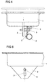
- Fig. 4
- die Seitenansicht der Ausführungsform nach Fig. 1 nach dem Aufschlag eines Insassenkopfes;
- Fig. 5
- die Ansicht von vorn der Ausführungsform nach Fig. 1 nach dem Aufschlag eines Insassenkopfes;
- Fig. 6
- die Seitenansicht eines Gehäuses mit einer zweiten Ausführungsform eines Langlochs in einer Führungslasche;
- Fig. 7
- die Seitenansicht eines Gehäuses mit einer dritten Ausführungsform eines Langlochs in einer Führungslasche.
- Fig. 8-11
- Kraft-Weg-Diagramme für verschiedene Ausführungsformen des Langloches.
Claims (19)
- Airbagmodul mit Gehäuse für die Aufnahme mindestens eines Gasgenerators und mindestens eines Gassacks, wobei zwischen dem Gehäuse und der Armaturentafel keine Verbindung besteht und wobei das Gehäuse vom Insassen wegbewegbar ist,
dadurch gekennzeichnet, daß das Gehäuse (1) mindestens ein Laschenpaar aufweist, das eine erste verformbare Lasche (3, 10) für die Befestigung des Gehäuses (1) auf einem Fahrzeugquerträger (4) und eine zweite mit einem sich im wesentlichen in Bewegungsrichtung des Gehäuses (1) erstreckenden Langloch (7) versehene Lasche (2) für die Führung mindestens eines Verbindungselementes (6) während der Bewegung des Gehäuses (1) und Dämpfung dieser Bewegung aufweist, wobei das Verbindungselement (6) die erste Lasche (3, 10) mit dem Fahrzeugquerträger (4) verbindet. - Airbagmodul nach Anspruch 1, dadurch gekennzeichnet, daß mindestens eine Kante des Langlochs (7) durch das Verbindungselement (6) bei der Bewegung des Langlochs (7) gegenüber dem Verbindungselement zur Erzielung der Dämpfung deformierbar ist.
- Airbagmodul nach Anspruch 1 oder 2, dadurch gekennzeichnet, daß das Verbindungselement (6) bei der Bewegung des Langlochs (7) gegenüber dem Verbindungselement zur Erzielung der Dämpfung verformbar ist.
- Airbagmodul nach mindestens einem der vorhergehenden Ansprüche, dadurch gekennzeichnet, daß sich das Langloch (7) in der zweiten Lasche (2) in Richtung des Bodens des Gehäuses (1) auf eine Breite verringert, die kleiner ist als die Breite bzw. der Durchmesser des Verbindungselementes (6).
- Airbagmodul nach mindestens einem der vorhergehenden Ansprüche, dadurch gekennzeichnet, daß sich die Breite des Langlochs (7) in Richtung des Bodens des Gehäuses (1) kontinuierlich verringert.
- Airbagmodul nach mindestens einem der vorhergehenden Ansprüche, dadurch gekennzeichnet, daß beide Kanten (11, 12) des Langlochs (7) schräg bezüglich der Bewegungsrichtung des Gehäuses (1) aufeinander zulaufen.
- Airbagmodul nach mindestens einem der vorhergehenden Ansprüche, dadurch gekennzeichnet, daß eine erste Kante (13) des Langlochs (7) parallel zur Bewegungsrichtung des Gehäuses (1) verläuft, während die andere Kante (14) schräg auf diese erste Kante (13) zuläuft.
- Airbagmodul nach mindestens einem der Ansprüche 1 bis 9, dadurch gekennzeichnet, daß die Kanten (15, 16) des Langlochs (7) parallel zueinander und schräg zur Bewegungsrichtung des Gehäuses (1) verlaufen.
- Airbagmodul nach mindestens einem der Ansprüche 1 bis 4, dadurch gekennzeichnet, daß sich das Langloch (7) in Richtung des Gehäusebodens zunächst auf eine Breite verringert, die kleiner als die Breite bzw. der Durchmesser des Verbindungselementes (6) ist, und daß die Kanten (17,18) anschließend parallel verlaufen.
- Airbagmodul nach mindestens einem der vorhergehenden Ansprüche, dadurch gekennzeichnet, daß sich das Langloch (7) an seinem dem Gehäuseboden zugekehrten Ende (7b) auf eine Breite erweitert, die der Breite bzw. dem Durchmesser des Verbindungselementes (6) entspricht.
- Airbagmodul nach Anspruch 10, dadurch gekennzeichnet, daß die Erweiterung kontinuierlich erfolgt.
- Airbagmodul nach Anspruch 11, dadurch gekennzeichnet, daß sich die Breite des Langlochs an seinem dem Boden des Gehäuses (1) zugekehrten Ende (7c) von der Breite, die dem Durchmesser des Verbindungselementes (6) entspricht, kontinuierlich verringert.
- Airbagmodul nach mindestens einem der vorhergehenden Ansprüche, dadurch gekennzeichnet, daß als Verbindungselement eine Schraube (6) vorgesehen ist, deren Schaft (6a) sich durch das Langloch (7) hindurch erstreckt.
- Airbagmodul mindestens einem der vorhergehenden Ansprüche, dadurch gekennzeichnet, daß die Laschen (2, 3, 10) in solchem Abstand zueinander angeordnet sind, daß Raum für eine Mutter (9) für eine Schraubverbindung zwischen der ersten Lasche (3, 10) und dem Fahrzeugquerträger (4) vorhanden ist.
- Airbagmodul nach mindestens einem der vorhergehenden Ansprüche, dadurch gekennzeichnet, daß die erste Lasche (3, 10) über eine am Fahrzeugquerträger (4) befestigte Halterung (5) mit diesem verbunden ist.
- Airbagmodul nach mindestens einem der vorhergehenden Ansprüche, dadurch gekennzeichnet, daß die Laschen (2, 3, 10) am Boden des Gehäuses (1) mit diesem verbunden sind.
- Airbagmodul nach mindestens einem der vorhergehenden Ansprüche, dadurch gekennzeichnet, daß die erste verformbare Lasche (3, 10) insgesamt verformbar ist.
- Airbagmodul nach mindestens einem der vorhergehenden Ansprüche, dadurch gekennzeichnet, daß die erste verformbare Lasche (10) eine deformierbare Schwachstelle (8) aufweist.
- Airbagmodul nach Anspruch 18, dadurch gekennzeichnet, daß als deformierbare Schwachstelle eine Knickstelle (8) vorgesehen ist.
Applications Claiming Priority (2)
| Application Number | Priority Date | Filing Date | Title |
|---|---|---|---|
| DE20310345U DE20310345U1 (de) | 2003-06-30 | 2003-06-30 | Airbagmodul mit Gehäuse für die Aufnahme mindestens eines Gasgenerators und mindestens eines Gassacks |
| DE20310345U | 2003-06-30 |
Publications (2)
| Publication Number | Publication Date |
|---|---|
| EP1493634A1 true EP1493634A1 (de) | 2005-01-05 |
| EP1493634B1 EP1493634B1 (de) | 2006-03-08 |
Family
ID=28685590
Family Applications (1)
| Application Number | Title | Priority Date | Filing Date |
|---|---|---|---|
| EP04090225A Expired - Lifetime EP1493634B1 (de) | 2003-06-30 | 2004-06-09 | Airbagmodul mit Gehäuse für die Aufnahme mindestens eines Gasgenerators und mindestens eines Gassacks |
Country Status (5)
| Country | Link |
|---|---|
| US (1) | US6983954B2 (de) |
| EP (1) | EP1493634B1 (de) |
| JP (1) | JP2005035541A (de) |
| CN (1) | CN100423971C (de) |
| DE (2) | DE20310345U1 (de) |
Cited By (1)
| Publication number | Priority date | Publication date | Assignee | Title |
|---|---|---|---|---|
| US9598039B2 (en) | 2013-07-15 | 2017-03-21 | Volkswagen Aktiengesellschaft | Instrument panel for a vehicle |
Families Citing this family (21)
| Publication number | Priority date | Publication date | Assignee | Title |
|---|---|---|---|---|
| DE10316543A1 (de) * | 2002-04-11 | 2003-11-13 | Toyoda Gosei Kk | Luftsackvorrichtung |
| DE10316542B4 (de) * | 2002-04-11 | 2011-08-11 | Toyoda Gosei Co., Ltd. | Luftsackvorrichtung für ein Fahrzeug und Verfahren zum Entfalten eines Luftsacks |
| US7290788B2 (en) * | 2003-09-03 | 2007-11-06 | Visteon Global Technologies, Inc. | Airbag bracket |
| DE102004025716B4 (de) * | 2004-05-26 | 2011-08-18 | Continental Automotive GmbH, 30165 | Airbagmodul |
| JP4666601B2 (ja) * | 2005-05-13 | 2011-04-06 | カルソニックカンセイ株式会社 | エアバッグ装置取付部構造 |
| KR100980929B1 (ko) | 2007-11-15 | 2010-09-07 | 기아자동차주식회사 | 하우징리스 타입 조수석 에어백 장치 |
| US7874576B2 (en) * | 2009-04-16 | 2011-01-25 | Toyota Motor Engineering & Manufacturing North America, Inc. | Adjustable airbag systems for vehicles |
| DE102009031120B4 (de) * | 2009-06-30 | 2017-07-27 | GM Global Technology Operations LLC (n. d. Ges. d. Staates Delaware) | Airbageinrichtung für ein Kraftfahrzeug |
| JP5130265B2 (ja) * | 2009-08-03 | 2013-01-30 | トヨタ自動車株式会社 | 助手席用エアバッグ装置の配設構造 |
| US8246074B2 (en) * | 2009-11-13 | 2012-08-21 | Hyundai Motor Company | Airbag mounting assembly for vehicles |
| JP5606296B2 (ja) * | 2010-11-30 | 2014-10-15 | ダイハツ工業株式会社 | 助手席用エアバッグのインフレータ取付構造 |
| US8414015B2 (en) | 2011-01-24 | 2013-04-09 | Nissan North America, Inc. | Vehicle airbag support structure |
| KR101337804B1 (ko) * | 2011-11-29 | 2013-12-06 | 쌍용자동차 주식회사 | 자동차용 에어백 브라켓의 충격 흡수구조 |
| US8540274B2 (en) | 2011-12-22 | 2013-09-24 | Nissan North America, Inc. | Vehicle airbag support assembly |
| JP5816662B2 (ja) * | 2013-08-29 | 2015-11-18 | 富士重工業株式会社 | 乗員保護装置 |
| US8910971B1 (en) * | 2014-04-24 | 2014-12-16 | Ford Global Technologies, Llc | Rotatable airbag module mounting mechanism |
| DE102016009455A1 (de) * | 2016-08-03 | 2018-02-08 | Audi Ag | Baugruppe für ein Kraftfahrzeug und Kraftfahrzeug mit einer Baugruppe |
| US9821746B1 (en) * | 2016-09-21 | 2017-11-21 | Ford Global Technologies, Llc | Airbag assembly |
| US10099647B2 (en) | 2016-09-21 | 2018-10-16 | Ford Global Technologies, Llc | Airbag assembly |
| JP7517269B2 (ja) | 2021-06-23 | 2024-07-17 | 株式会社島津製作所 | 真空ポンプおよび固定構造 |
| FR3161633A1 (fr) * | 2024-04-25 | 2025-10-31 | Stellantis Auto Sas | Patte de fixation à double fonction, pour un dispositif de protection à sac gonflable d’un véhicule |
Citations (3)
| Publication number | Priority date | Publication date | Assignee | Title |
|---|---|---|---|---|
| DE4435451A1 (de) * | 1993-10-04 | 1995-04-06 | Nsk Ltd | Airbagsystem |
| DE4430588C1 (de) * | 1994-08-19 | 1995-10-12 | Petri Ag | Gassack (Airbag)-System für Kraftfahrzeuge |
| DE19751991A1 (de) * | 1996-11-22 | 1998-05-28 | Trw Vehicle Safety Systems | Airbag-Modul |
Family Cites Families (8)
| Publication number | Priority date | Publication date | Assignee | Title |
|---|---|---|---|---|
| JPH02299951A (ja) * | 1989-01-23 | 1990-12-12 | Mazda Motor Corp | 自動車のエアバッグ配設構造 |
| JPH08282425A (ja) * | 1995-04-20 | 1996-10-29 | Honda Motor Co Ltd | エアバッグ装置 |
| US6176511B1 (en) * | 1998-10-07 | 2001-01-23 | Trw Inc. | Air bag module |
| JP3962967B2 (ja) * | 1999-02-19 | 2007-08-22 | スズキ株式会社 | ペダルブラケット取付構造 |
| US6286858B1 (en) * | 1999-07-29 | 2001-09-11 | Delphi Technologies, Inc. | Energy absorbing air bag module |
| JP4380934B2 (ja) * | 2001-04-05 | 2009-12-09 | 株式会社ジェイテクト | 衝撃吸収式ステアリング装置 |
| JP2002337699A (ja) * | 2001-05-15 | 2002-11-27 | Koyo Seiko Co Ltd | 衝撃吸収式ステアリング装置 |
| DE10161446B4 (de) | 2001-12-14 | 2005-06-30 | Daimlerchrysler Ag | Airbaggehäuse |
-
2003
- 2003-06-30 DE DE20310345U patent/DE20310345U1/de not_active Expired - Lifetime
-
2004
- 2004-06-09 DE DE502004000340T patent/DE502004000340D1/de not_active Expired - Fee Related
- 2004-06-09 EP EP04090225A patent/EP1493634B1/de not_active Expired - Lifetime
- 2004-06-29 JP JP2004219422A patent/JP2005035541A/ja not_active Ceased
- 2004-06-30 US US10/879,185 patent/US6983954B2/en not_active Expired - Fee Related
- 2004-06-30 CN CNB2004100632012A patent/CN100423971C/zh not_active Expired - Fee Related
Patent Citations (3)
| Publication number | Priority date | Publication date | Assignee | Title |
|---|---|---|---|---|
| DE4435451A1 (de) * | 1993-10-04 | 1995-04-06 | Nsk Ltd | Airbagsystem |
| DE4430588C1 (de) * | 1994-08-19 | 1995-10-12 | Petri Ag | Gassack (Airbag)-System für Kraftfahrzeuge |
| DE19751991A1 (de) * | 1996-11-22 | 1998-05-28 | Trw Vehicle Safety Systems | Airbag-Modul |
Non-Patent Citations (1)
| Title |
|---|
| ANONYMOUS: "Movable air bag module", RESEARCH DISCLOSURE, KENNETH MASON PUBLICATIONS, HAMPSHIRE, GB, vol. 424, no. 64, August 1999 (1999-08-01), XP007124709, ISSN: 0374-4353 * |
Cited By (1)
| Publication number | Priority date | Publication date | Assignee | Title |
|---|---|---|---|---|
| US9598039B2 (en) | 2013-07-15 | 2017-03-21 | Volkswagen Aktiengesellschaft | Instrument panel for a vehicle |
Also Published As
| Publication number | Publication date |
|---|---|
| DE20310345U1 (de) | 2003-09-25 |
| EP1493634B1 (de) | 2006-03-08 |
| US20040262890A1 (en) | 2004-12-30 |
| JP2005035541A (ja) | 2005-02-10 |
| DE502004000340D1 (de) | 2006-05-04 |
| CN1576113A (zh) | 2005-02-09 |
| US6983954B2 (en) | 2006-01-10 |
| CN100423971C (zh) | 2008-10-08 |
Similar Documents
| Publication | Publication Date | Title |
|---|---|---|
| EP1493634A1 (de) | Airbagmodul mit Gehäuse für die Aufnahme mindestens eines Gasgenerators und mindestens eines Gassacks | |
| EP2119589B1 (de) | Einrichtung für eine Sitzlängsverstellung, insbesondere innerhalb eines Kfz | |
| DE19812701B4 (de) | Karosseriestruktur für den Frontbereich eines Kraftfahrzeuges | |
| DE102017222225B4 (de) | Kraftfahrzeug mit Hilfsrahmen | |
| DE4105679A1 (de) | Vorderer fahrzeugaufbau fuer kraftfahrzeuge und verfahren zum zusammenbau eines solchen fahrzeugaufbaus | |
| DE3023035A1 (de) | Fahrzeugsitz, insbesondere fuer kraftfahrzeuge | |
| DE19830303B4 (de) | Anordnung eines Instrumententafelträgers in einer Fahrzeugkarosserie und Instrumententafelträger | |
| EP0324907B1 (de) | Anordnung eines frontseitigen Antriebsaggregats in einem Kraftfahrzeug | |
| DE102022113406B3 (de) | Seitenschweller für eine Kraftwagenkarosserie | |
| DE102004007630B4 (de) | Airbagmodul-Halterung | |
| EP2040970A1 (de) | Anordnung zur befestigung einer lenksäule eines kraftfahrzeuges | |
| DE10033340C1 (de) | Sitzbefestigungsvorrichtung | |
| DE19706225C2 (de) | Kraftfahrzeug mit einer Abstützung zwischen Querträger und Spritzschutzwand | |
| DE102019113222B4 (de) | Befestigungsanordnung zur Befestigung einer Stoßfängerverkleidung an einer Seitenwand eines Kraftfahrzeugs und Kraftfahrzeug | |
| DE102020124396A1 (de) | Kraftfahrzeug mit Sitzschienendämpfer | |
| EP4204255B1 (de) | Längseinsteller, verfahren zur montage eines längseinstellers und fahrzeugsitz | |
| DE10107694C1 (de) | Kraftfahrzeugsitz, mit einem höhenverstellbaren Sitzträger | |
| DE102020116604B4 (de) | Fahrzeugrahmen mit zwei Längsträgern | |
| DE19706609C5 (de) | Vorrichtung zur Befestigung des Lenkrads in einem Kraftfahrzeug | |
| DE102006059096A1 (de) | Baugruppe zur fahrzeugseitigen Befestigung eines Gurtschlosses | |
| DE10337545A1 (de) | Befestigungseinrichtung und Kühlergrillanordnung | |
| DE102024208057A1 (de) | Lenksäulenbaugruppe | |
| DE102005027537B4 (de) | Baugruppe für ein Kraftfahrzeug | |
| DE102024115428A1 (de) | Anordnung zur Lagerung eines Lenkers an einem Hilfsrahmen eines Kraftfahrzeugs sowie Kraftfahrzeug | |
| DE102010024769B4 (de) | Motorlager |
Legal Events
| Date | Code | Title | Description |
|---|---|---|---|
| PUAI | Public reference made under article 153(3) epc to a published international application that has entered the european phase |
Free format text: ORIGINAL CODE: 0009012 |
|
| AK | Designated contracting states |
Kind code of ref document: A1 Designated state(s): AT BE BG CH CY CZ DE DK EE ES FI FR GB GR HU IE IT LI LU MC NL PL PT RO SE SI SK TR |
|
| AX | Request for extension of the european patent |
Extension state: AL HR LT LV MK |
|
| 17P | Request for examination filed |
Effective date: 20050622 |
|
| GRAP | Despatch of communication of intention to grant a patent |
Free format text: ORIGINAL CODE: EPIDOSNIGR1 |
|
| AKX | Designation fees paid |
Designated state(s): DE FR GB SE |
|
| GRAS | Grant fee paid |
Free format text: ORIGINAL CODE: EPIDOSNIGR3 |
|
| GRAA | (expected) grant |
Free format text: ORIGINAL CODE: 0009210 |
|
| AK | Designated contracting states |
Kind code of ref document: B1 Designated state(s): DE FR GB SE |
|
| REG | Reference to a national code |
Ref country code: GB Ref legal event code: FG4D Free format text: NOT ENGLISH |
|
| REF | Corresponds to: |
Ref document number: 502004000340 Country of ref document: DE Date of ref document: 20060504 Kind code of ref document: P |
|
| REG | Reference to a national code |
Ref country code: SE Ref legal event code: TRGR |
|
| GBT | Gb: translation of ep patent filed (gb section 77(6)(a)/1977) |
Effective date: 20060517 |
|
| ET | Fr: translation filed | ||
| PLBE | No opposition filed within time limit |
Free format text: ORIGINAL CODE: 0009261 |
|
| STAA | Information on the status of an ep patent application or granted ep patent |
Free format text: STATUS: NO OPPOSITION FILED WITHIN TIME LIMIT |
|
| 26N | No opposition filed |
Effective date: 20061211 |
|
| PGFP | Annual fee paid to national office [announced via postgrant information from national office to epo] |
Ref country code: DE Payment date: 20080612 Year of fee payment: 5 Ref country code: SE Payment date: 20080609 Year of fee payment: 5 |
|
| PGFP | Annual fee paid to national office [announced via postgrant information from national office to epo] |
Ref country code: FR Payment date: 20080617 Year of fee payment: 5 |
|
| PGFP | Annual fee paid to national office [announced via postgrant information from national office to epo] |
Ref country code: GB Payment date: 20080611 Year of fee payment: 5 |
|
| GBPC | Gb: european patent ceased through non-payment of renewal fee |
Effective date: 20090609 |
|
| REG | Reference to a national code |
Ref country code: FR Ref legal event code: ST Effective date: 20100226 |
|
| PG25 | Lapsed in a contracting state [announced via postgrant information from national office to epo] |
Ref country code: FR Free format text: LAPSE BECAUSE OF NON-PAYMENT OF DUE FEES Effective date: 20090630 |
|
| PG25 | Lapsed in a contracting state [announced via postgrant information from national office to epo] |
Ref country code: GB Free format text: LAPSE BECAUSE OF NON-PAYMENT OF DUE FEES Effective date: 20090609 |
|
| PG25 | Lapsed in a contracting state [announced via postgrant information from national office to epo] |
Ref country code: DE Free format text: LAPSE BECAUSE OF NON-PAYMENT OF DUE FEES Effective date: 20100101 |
|
| PG25 | Lapsed in a contracting state [announced via postgrant information from national office to epo] |
Ref country code: SE Free format text: LAPSE BECAUSE OF NON-PAYMENT OF DUE FEES Effective date: 20090610 |