EP1493542B1 - Procédé de traitement de fûts en bois et dispositif pour sa mise en oeuvre - Google Patents
Procédé de traitement de fûts en bois et dispositif pour sa mise en oeuvre Download PDFInfo
- Publication number
- EP1493542B1 EP1493542B1 EP04362006A EP04362006A EP1493542B1 EP 1493542 B1 EP1493542 B1 EP 1493542B1 EP 04362006 A EP04362006 A EP 04362006A EP 04362006 A EP04362006 A EP 04362006A EP 1493542 B1 EP1493542 B1 EP 1493542B1
- Authority
- EP
- European Patent Office
- Prior art keywords
- barrel
- shell
- initial heat
- wooden
- tool
- Prior art date
- Legal status (The legal status is an assumption and is not a legal conclusion. Google has not performed a legal analysis and makes no representation as to the accuracy of the status listed.)
- Expired - Lifetime
Links
- 238000000034 method Methods 0.000 title claims abstract description 25
- 235000014101 wine Nutrition 0.000 claims description 16
- 230000032683 aging Effects 0.000 claims description 4
- 235000015096 spirit Nutrition 0.000 claims description 2
- 230000015572 biosynthetic process Effects 0.000 claims 2
- 239000000463 material Substances 0.000 abstract description 4
- 230000000717 retained effect Effects 0.000 abstract description 3
- 239000002023 wood Substances 0.000 description 15
- 238000010438 heat treatment Methods 0.000 description 12
- 125000003118 aryl group Chemical group 0.000 description 4
- 238000005520 cutting process Methods 0.000 description 3
- 238000004519 manufacturing process Methods 0.000 description 3
- 239000007788 liquid Substances 0.000 description 2
- 238000006243 chemical reaction Methods 0.000 description 1
- 239000011248 coating agent Substances 0.000 description 1
- 238000000576 coating method Methods 0.000 description 1
- 238000003754 machining Methods 0.000 description 1
- 238000012423 maintenance Methods 0.000 description 1
- 239000002184 metal Substances 0.000 description 1
- 230000001737 promoting effect Effects 0.000 description 1
- 238000011084 recovery Methods 0.000 description 1
- 239000007787 solid Substances 0.000 description 1
Images


Classifications
-
- B—PERFORMING OPERATIONS; TRANSPORTING
- B27—WORKING OR PRESERVING WOOD OR SIMILAR MATERIAL; NAILING OR STAPLING MACHINES IN GENERAL
- B27K—PROCESSES, APPARATUS OR SELECTION OF SUBSTANCES FOR IMPREGNATING, STAINING, DYEING, BLEACHING OF WOOD OR SIMILAR MATERIALS, OR TREATING OF WOOD OR SIMILAR MATERIALS WITH PERMEANT LIQUIDS, NOT OTHERWISE PROVIDED FOR; CHEMICAL OR PHYSICAL TREATMENT OF CORK, CANE, REED, STRAW OR SIMILAR MATERIALS
- B27K5/00—Treating of wood not provided for in groups B27K1/00, B27K3/00
- B27K5/001—Heating
-
- B—PERFORMING OPERATIONS; TRANSPORTING
- B27—WORKING OR PRESERVING WOOD OR SIMILAR MATERIAL; NAILING OR STAPLING MACHINES IN GENERAL
- B27H—BENDING WOOD OR SIMILAR MATERIAL; COOPERAGE; MAKING WHEELS FROM WOOD OR SIMILAR MATERIAL
- B27H5/00—Manufacture of tubes, coops, or barrels
- B27H5/08—Finishing barrels, e.g. cutting grooves
-
- C—CHEMISTRY; METALLURGY
- C12—BIOCHEMISTRY; BEER; SPIRITS; WINE; VINEGAR; MICROBIOLOGY; ENZYMOLOGY; MUTATION OR GENETIC ENGINEERING
- C12H—PASTEURISATION, STERILISATION, PRESERVATION, PURIFICATION, CLARIFICATION OR AGEING OF ALCOHOLIC BEVERAGES; METHODS FOR ALTERING THE ALCOHOL CONTENT OF FERMENTED SOLUTIONS OR ALCOHOLIC BEVERAGES
- C12H1/00—Pasteurisation, sterilisation, preservation, purification, clarification, or ageing of alcoholic beverages
- C12H1/22—Ageing or ripening by storing, e.g. lagering of beer
Definitions
- the present invention relates to a process for treating or repackaging wooden barrels and to a device for its implementation.
- a wooden barrel in which the wine is conserved for a more or less long duration, generally varying from 10 to 18 months.
- the aging in wooden casks is particularly recommended for the wines of guard because of the tannic and aromatic exchanges between the wood and the wine.
- the wooden barrel can take different names, barrels, barrels or the like, depending on its shape, size and region.
- the barrel usually includes a body called shell consisting of staves with each end funds.
- the barrel is subjected to a step called heating, during which said barrel without bottom is placed over a fire for burning staves.
- the purpose of the heating is to modulate the aromatic and tannic nature of the wood by varying the duration and intensity of the heating. This heating affects the wood to a greater or lesser thickness, depending on the heating technique used.
- a first solution for repackaging a drum is to clean with a suitable liquid the inner wall in order to remove the deposit, in particular by chemical reaction, to allow again the exchanges between the wood and the wood. wine.
- This solution is not satisfactory because even cleaned, the wood of the inner wall no longer offers the same exchange as a new barrel.
- Another solution is to scrape or plane on a small thickness the inner wall of the barrel to remove the deposit. In this case, part of the heating, carried out during manufacture, is preserved.
- the present invention aims at overcoming the drawbacks of the prior art by proposing a new process for reconditioning wooden barrels used for raising wine, spirits or the like, making it possible to obtain results superior to existing techniques, approaching the results obtained with a new drum.
- This solution makes it possible, in a simple manner and for a relatively low cost price, to repackage the barrels in order to obtain characteristics approaching those of a new barrel.
- barrel means any wooden container likely to take different names, barrels, barrels, barrels or the like, depending on its shape, its size and the geographical area.
- the body generally comprises a body called shell 12 consisting of staves 14 with at each end funds 16.
- the staves are held in position by circles 18 preferably metal.
- the body has a throat called jable apt to house the periphery of the funds, so real estate funds by tightening the hull.
- the barrel 10 is subjected to a step called initial heating, in which said barrel without bottom is disposed above a fire for burning staves.
- This heater is materialized on the Figure 2A by a zone 20 in the wood.
- a deposit 22 is formed at the inner surface of the barrel, reducing the exchanges between the wood and the wine. This deposit 22 is found both at the inner surfaces of the shell 12 and the interior surfaces of the bottoms 16.
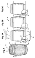
- the repackaging method of the invention consists in removing the bottoms 16, removing the initial heating on at least a part of the inner surface of the barrel, in particular of the shell 12, as illustrated by FIG. Figure 2B , and to achieve a new heating, materialized by the zone 24 in the wood, of variable intensity and duration depending on the aromatic and tannic nature of the desired wood, as illustrated by the Figure 2C .
- the funds 16 can be changed, returned in order to have the face on which the depot 22 is exposed to the outside, cleaned, or scraped in order to remove the deposit 22.
- the hull is loose. It is advantageously tightened prior to the step of removing the initial heat to prevent dislocation.
- the heater may be removed along the entire length of the staves or on a part, preferably between the stanchions.
- the funds are not changed but also reconditioned, the inner or outer surface of the funds being planed and heated.
- the hull and the funds undergo in the end a phase of sanding and finishing.
- the inner wall is planed to a sufficient depth to remove the entire initial heat.
- the new heater is practiced on wood that has never been heated.
- This device comprises a frame 26 with means 28 for holding and rotating a step 12 of a shell 12 and a tool 30 capable of translating parallel to the staves of the shell of said barrel to remove the initial heater 20.
- the tool 30 is in the form of a roller 32 pivotable about an axis 34, with a rough active surface 36 whose radius of curvature is adapted to the inner radius of the shell 12.
- tool 30 comprises on both sides of the roller 32 two crowns capable of bearing against the inner wall of the drum, said roller having a portion of the active surface 36 projecting from the crowns.
- a motorization is provided for the rotation of the roller 32 as well as return means, in the form of a pneumatic jack for example, to maintain the roller 32 pressed against the inner wall of the shell despite the curve of said shell, and exercise a cutting effort to remove material.
- the tool 30 is preferably disposed at the end of an arm 38 capable of translating parallel to the staves.
- the arm 38 is telescopic.
- the tool arm 38 comprises at its lower free end the tool 30 and is pivotally mounted at its upper end relative to a base capable of slide vertically on at least one slide with an actuator, including hydraulic cylinders.
- the means 28 for holding and rotating in steps of a shell 12 comprise a plate 40 with an upper housing 42 in which is likely to fit, including interlocking, an end of the shell.
- the plate 40 comprises rotating means.
- the plate 40 pivots so as to dispose the tool in the right of a non-machined zone.
- the housing 42 corresponds to the orifice of a ring removably attached to the plate 40.
- the device can quickly adapt to different barrel diameters by changing only the crown.
- the barrel is arranged vertically so that the cutting forces tend to push the barrel down towards the plate 40 to increase the jamming pressure of the barrel in the housing 42 and to promote the maintenance of the barrel. According to this arrangement, a better recovery of the cutting forces is obtained.
- the vertical disposition of the barrel promotes the evacuation of the chips which fall in the lower part and are then sucked.
- At least one actuator may be provided under the plate 40 capable of pushing the barrel upwards.
- the holding means 28 comprise a ring 44 adapted to hold the upper end of the shell.
- This ring 44 is pivotally mounted on a frame 46 capable of translating between two extreme positions, a first in which the ring 44 maintains the shell and a second in which the ring 44 no longer holds the shell to remove or introduce it in the housing 42 of the tray 40.
- this crown 44 is removably attached to the frame 46 to be changed quickly and adapted the device to the diameter of the barrel.
- the frame 46 includes an aperture adapted to fitably receive the upper end of the shell, the surface in contact with the shell having a slip promoting coating.
- the frame 26 comprises a base 48 on which is attached the plate 40 and at least one upright 50 to which the frame 46 and the arm 38 are connected.
- a shell 12 is inserted into the housing 42 of the plate 40 as shown in FIG. figure 3 . Then, the frame 46 is translated downwards so that the upper end of the shell is held by the ring 44, as illustrated by the Figure 5A . Following these steps, the shell is secured to the device and the machining operation can begin.
- the tool 30 is then translated parallel to the staves as illustrated by the Figure 5B and remove material at the inner surface of the shell, as illustrated by figure 4 .
- the plate 40 pivots as illustrated on the Figure 5C so that the tool is arranged at the right of a non-machined zone, preferably juxtaposed with the previously machined strip.
- the tool 30 again translates to remove a new band and so on over the entire periphery of the hull.
- the invention is obviously not limited to the embodiment shown and described above, but covers all variants, particularly with respect to the device for removing the initial heater.
- this method of treating a barrel can be applied to any wooden container, whether used to package a liquid or a solid.
Landscapes
- Engineering & Computer Science (AREA)
- Life Sciences & Earth Sciences (AREA)
- Wood Science & Technology (AREA)
- Chemical & Material Sciences (AREA)
- Organic Chemistry (AREA)
- Forests & Forestry (AREA)
- Bioinformatics & Cheminformatics (AREA)
- Health & Medical Sciences (AREA)
- Manufacturing & Machinery (AREA)
- Biochemistry (AREA)
- Mechanical Engineering (AREA)
- General Engineering & Computer Science (AREA)
- General Health & Medical Sciences (AREA)
- Genetics & Genomics (AREA)
- Food Science & Technology (AREA)
- Zoology (AREA)
- Chemical And Physical Treatments For Wood And The Like (AREA)
- Shovels (AREA)
- Alcoholic Beverages (AREA)
Description
- La présente invention se rapporte à un procédé de traitement ou de reconditionnement de fûts en bois ainsi qu'à un dispositif pour sa mise en oeuvre. Pour l'élevage du vin, on utilise généralement un fût en bois dans lequel le vin est conservé pendant une durée plus ou moins longue, variant généralement de 10 à 18 mois. L'élevage en fût de bois est notamment préconisé pour les vins de garde en raison des échanges tannique et aromatique entre le bois et le vin.
- Le fût en bois peut prendre différentes appellations, barriques, tonneaux ou analogues, en fonction de ses formes, de ses dimensions et de la région.
- Il comprend généralement un corps appelé coque constituée de douelles avec à chaque extrémité des fonds. Lors de sa fabrication, le fût est soumis à une étape appelée chauffe, lors de laquelle ledit fût dépourvu de fond est disposé au-dessus d'un feu pour le brûlage des douelles. La chauffe a pour objectif de moduler la nature aromatique et tannique du bois en jouant sur la durée et l'intensité de la chauffe. Cette chauffe affecte le bois sur une épaisseur plus ou moins importante, en fonction de la technique de chauffe utilisée.
- Lors de l'élevage du vin, un dépôt apparaît au niveau de la surface intérieure du fût, réduisant les échanges entre le bois et le vin. Aussi, après avoir servi à élever deux vins, le fût de bois doit être changé ou reconditionné.
- Une première solution pour reconditionner un fût consiste à nettoyer avec un liquide adapté la paroi intérieure afin de retirer le dépôt, notamment par réaction chimique, pour permettre de nouveau les échanges entre le bois et le vin. Cette solution n'est pas satisfaisante car même nettoyé, le bois de la paroi intérieure n'offre plus les mêmes échanges qu'un fût neuf.
- Une autre solution consiste à gratter ou raboter sur une faible épaisseur la paroi intérieure du fût afin de retirer le dépôt. Dans ce cas, une partie de la chauffe, réalisée lors de la fabrication, est conservée.
- Si on ne pratique pas une nouvelle chauffe, les échanges obtenus après reconditionnement sont bien moindres que ceux obtenus avec un fût neuf.
- Si on pratique une nouvelle chauffe, le bois de la paroi intérieure qui a conservé une partie de la chauffe initiale est brûlé ce qui affecte les qualités organoleptiques du vin élevé.
- Aussi, la présente invention vise à pallier les inconvénients de l'art antérieur en proposant un nouveau procédé de reconditionnement de fûts en bois utilisés pour l'élevage du vin, des spiritueux ou analogue, permettant d'obtenir des résultats supérieurs aux techniques existantes, s'approchant des résultats obtenus avec un fût neuf.
- A cet effet, l'invention a pour objet un procédé pour le traitement d'un fût en bois, notamment utilisé pour élever un vin, un spiritueux ou analogue, ledit fût ayant subi une chauffe dite initiale caractérisé en ce qu'il comprend les étapes suivantes consistant à :
- retirer la chauffe initiale sur au moins une partie de la surface intérieure du fût, et
- réaliser une nouvelle chauffe, d'intensité et durée variable en fonction de la nature aromatique et tannique du bois souhaitée.
- Cette solution permet, de manière simple et pour un coût de revient relativement faible, de reconditionner les fûts afin d'obtenir des caractéristiques s'approchant de celles d'un fût neuf.
- D'autres caractéristiques et avantages ressortiront de la description qui va suivre de l'invention, description donnée à titre d'exemple uniquement, en regard des dessins annexés sur lesquels:
- la
figure 1 est une vue en perspective d'un fût en bois, - les
figures 2A à 2C sont des vues latérales illustrant les étapes du procédé de l'invention, - la
figure 3 est une vue en élévation latérale du dispositif utilisé pour la mise en oeuvre du procédé de l'invention, - la
figure 4 est une vue de dessus illustrant l'outil du dispositif, et - les
figures 5A à 5C sont des vues latérales illustrant le fonctionnement du dispositif de l'invention. - Sur la
figure 1 , on a représenté en 10 un fût en bois utilisé pour élever un vin. Par fût, on entend tout contenant en bois susceptible de prendre différentes appellations, fûts, barriques, tonneaux ou analogues, en fonction de ses formes, de ses dimensions et de la zone géographique. - Il comprend généralement un corps appelé coque 12 constituée de douelles 14 avec à chaque extrémité des fonds 16. Les douelles sont maintenues en position grâce à des cercles 18 de préférence métalliques. A chaque extrémité, le corps présente une gorge appelée jable apte à loger la périphérie des fonds, afin d'immobilier les fonds par resserrage de la coque.
- Lors de sa fabrication, le fût 10 est soumis à une étape appelée chauffe initiale, lors de laquelle ledit fût dépourvu de fond est disposé au-dessus d'un feu pour le brûlage des douelles. Cette chauffe est matérialisée sur la
figure 2A par une zone 20 dans le bois. - Lors de l'élevage du vin, un dépôt 22 se forme au niveau de la surface intérieure du fût, réduisant les échanges entre le bois et le vin. On retrouve ce dépôt 22 tant au niveau des surfaces intérieures de la coque 12 que des surfaces intérieures des fonds 16.
- Le procédé de reconditionnement de l'invention consiste à retirer les fonds 16, à retirer la chauffe initiale sur au moins une partie de la surface intérieure du fût, notamment de la coque 12, comme illustré par la
figure 2B , et à réaliser une nouvelle chauffe, matérialisée par la zone 24 dans le bois, d'intensité et de durée variables en fonction de la nature aromatique et tannique du bois souhaitée, comme illustré par lafigure 2C . - Selon les cas, les fonds 16 peuvent être changés, retournés afin de disposer la face sur laquelle est présent le dépôt 22 vers l'extérieur, nettoyés, ou grattés afin de retirer le dépôt 22.
- Pour retirer les fonds, la coque est desserrée. Elle est avantageusement resserrée préalablement à l'étape de retrait de la chauffe initiale afin d'éviter toute dislocation.
- On peut retirer la chauffe sur toute la longueur des douelles ou sur une partie, de préférence entre les jables.
- De préférence, les fonds ne sont pas changés mais également reconditionnés, la surface intérieure ou extérieure des fonds étant rabotée et chauffée.
- Si les fonds sont retournés, c'est-à-dire si la surface disposée initialement vers l'extérieur est disposée après reconditionnement vers l'intérieur, les formes des jables et/ou la périphérie des fonds sont travaillées pour de nouveau coopérer.
- Avantageusement, la coque et les fonds subissent à la fin une phase de ponçage et de finition.
- Contrairement au solution existante, la paroi intérieure est rabotée sur une profondeur suffisante de manière à retirer l'intégralité de la chauffe initiale. Ainsi, la nouvelle chauffe est pratiquée sur du bois n'ayant jamais subi une chauffe.
- De manière surprenante, on note que les échanges sont supérieurs à ceux obtenus avec un fût neuf car le bois du fût reconditionné selon l'invention est plus sec que lors du premier passage du vin.
- Sur les
figures 3, 4 ,5A, 5B et 5C , on a représenté un dispositif apte à retirer la chauffe initiale 20. - Ce dispositif comprend un bâti 26 avec des moyens 28 de maintien et de mise en rotation pas à pas d'une coque 12 et un outil 30 susceptible de se translater parallèlement aux douelles de la coque dudit fût afin de retirer la chauffe 20 initiale.
- Selon un mode de réalisation préféré, illustré par la
figure 4 , l'outil 30 se présente sous la forme d'un galet 32 susceptible de pivoter autour d'un axe 34, avec une surface active 36 rugueuse dont le rayon de courbure est adapté au rayon intérieur de la coque 12. En complément, l'outil 30 comprend de part et d'autre du galet 32 deux couronnes susceptibles de prendre appui contre la paroi intérieure du fût, ledit galet ayant une partie de la surface active 36 en saillie par rapport aux couronnes. Ainsi, pour régler la profondeur de passe, il suffit d'ajuster la position relative des galets et des couronnes. - Une motorisation est prévue pour la mise en rotation du galet 32 ainsi que des moyens de rappel, sous forme d'un vérin pneumatique par exemple, permettant de maintenir le galet 32 plaqué contre la paroi intérieure de la coque malgré le galbe de ladite coque, et d'exercer un effort de coupe afin de retirer de la matière.
- L'outil 30 est de préférence disposé à l'extrémité d'un bras 38 susceptible de se translater parallèlement aux douelles. De préférence, le bras 38 est télescopique. Selon un autre mode de réalisation, le bras 38 porte outil comprend au niveau de son extrémité libre inférieure l'outil 30 et est monté pivotant au niveau de son extrémité supérieure par rapport à une base susceptible de coulisser verticalement sur au moins une glissière grâce à un actionneur, notamment des vérins hydrauliques.
- Les moyens 28 de maintien et de mise en rotation pas à pas d'une coque 12 comprennent un plateau 40 avec en partie supérieure un logement 42 dans lequel est susceptible de se loger, notamment s'emboîter, une extrémité de la coque. Le plateau 40 comprend des moyens de mise en rotation. Ainsi, lorsque l'outil 30 a usiné une bande, le plateau 40 pivote de manière à disposer l'outil au droit d'une zone non usinée.
- Avantageusement, le logement 42 correspond à l'orifice d'une couronne rapportée de manière démontable sur le plateau 40. Ainsi, le dispositif peut s'adapter rapidement à différents diamètres de fûts en changeant uniquement la couronne.
- On note que le fût est disposé verticalement si bien que les efforts de coupe tendent à pousser le fût vers le bas en direction du plateau 40 permettant d'accroître la pression de coincement du fût dans le logement 42 et de favoriser le maintien du fût. Selon cet agencement, on obtient une meilleure reprise des efforts de coupe.
- La disposition verticale du fût favorise l'évacuation des copeaux qui tombent en partie inférieure et sont ensuite aspirés.
- Afin de faciliter le retrait du fût du logement 42, au moins un actionneur peut être prévu sous le plateau 40 susceptible de pousser le fût vers le haut.
- Avantageusement, les moyens 28 de maintien comprennent une couronne 44 apte à maintenir l'extrémité supérieure de la coque. Cette couronne 44 est montée pivotante sur un cadre 46 susceptible de se translater entre deux positions extrêmes, une première dans laquelle la couronne 44 maintient la coque et une seconde dans laquelle la couronne 44 ne maintient plus la coque afin de la retirer ou l'introduire dans le logement 42 du plateau 40. Comme précédemment, cette couronne 44 est rapportée de manière démontable sur le cadre 46 pour être changée rapidement et adaptée le dispositif au diamètre du fût.
- En variante, le cadre 46 comprend une ouverture apte à recevoir de manière ajustée l'extrémité supérieure de la coque, la surface en contact avec la coque comportant un revêtement favorisant le glissement.
- Selon un mode de réalisation, le bâti 26 comprend un socle 48 sur lequel est rapporté le plateau 40 et au moins un montant 50 auquel sont reliées le cadre 46 et le bras 38.
- Le mode de fonctionnement du dispositif est maintenant expliqué au regard des
figures 3, 4 et5A à 5C . - Une coque 12 est introduite dans le logement 42 du plateau 40 comme illustré sur la
figure 3 . Ensuite, le cadre 46 se translate vers le bas afin que l'extrémité supérieure de la coque soit maintenue par la couronne 44, comme illustré par lafigure 5A . Suite à ces étapes, la coque est solidarisée au dispositif et l'opération d'usinage peut commencer. - L'outil 30 se translate alors parallèlement aux douelles comme illustré par la
figure 5B et retire de la matière au niveau de la surface intérieure de la coque, comme illustré par lafigure 4 . - Lorsque l'outil 30 a retiré une bande de matière, l'outil est dégagé et n'est plus en contact avec la surface de la coque. A cet instant, le plateau 40 pivote comme illustré sur la
figure 5C afin que l'outil soit disposé au droit d'une zone non usinée, de préférence juxtaposée à la bande précédemment usinée. - L'outil 30 effectue de nouveau une translation afin de retirer une nouvelle bande et ainsi de suite sur toute la périphérie de la coque.
- Bien entendu, l'invention n'est évidemment pas limitée au mode de réalisation représenté et décrit ci-dessus, mais en couvre au contraire toutes les variantes, notamment en ce qui concerne le dispositif prévu pour retirer la chauffe initiale.
- Enfin, ce procédé de traitement d'un fût peut s'appliquer à tout contenant en bois, qu'il soit utilisé pour conditionner un liquide ou un solide.
Claims (8)
- Procédé pour le traitement d'un fût (10) en bois, notamment utilisé pour élever un vin, un spiritueux ou analogue, ledit fût (10) ayant subi une chauffe (20) dite initiale caractérisé en ce qu'il comprend les étapes suivantes consistant à :- retirer la chauffe initiale (20) sur au moins une partie de la surface intérieure du fût (10), et- réaliser une nouvelle chauffe (24).
- Procédé selon la revendication 1, caractérisé en ce qu'on retire la chauffe initiale (20) par enlèvement de matière entre les jables de la coque.
- Procédé selon la revendication 1, caractérisé en ce qu'on retire la chauffe initiale (20) par enlèvement de matière sur toute la longueur de la coque (12).
- Procédé selon la revendication 3, caractérisé en ce que les formes des jables sont de nouveau travaillées pour coopérer avec la périphérie des fonds.
- Procédé selon l'une quelconque des revendications 1 à 4, caractérisé en ce que les fonds du fût sont reconditionnés.
- Procédé selon la revendication 5, caractérisé en ce qu'au moins une des surfaces des fonds est rabotée et chauffée.
- Dispositif pour la mise en oeuvre du procédé selon l'une quelconque des revendications 1 à 6, comprenant des moyens (28) de maintien et de mise en rotation pas à pas d'une coque (12) et un outil (30) susceptible de se translater parallèlement aux douelles de la coque, caractérisé en ce que les moyens (28) de maintien et de mise en rotation pas à pas comprennent un plateau (40) susceptible de pivoter, avec un logement (42) dont le diamètre est adapté à celui de la coque afin que ladite coque soit immobiliser par coincement dans ledit logement dans une position verticale.
- Dispositif selon la revendication 7, caractérisé en ce que les moyens (28) de maintien comprennent une couronne (44) apte à maintenir l'extrémité supérieure de la coque.
Applications Claiming Priority (2)
| Application Number | Priority Date | Filing Date | Title |
|---|---|---|---|
| FR0307784A FR2856623B1 (fr) | 2003-06-27 | 2003-06-27 | Procede de traitement de futs en bois et dispositif pour sa mise en oeuvre |
| FR0307784 | 2003-06-27 |
Publications (2)
| Publication Number | Publication Date |
|---|---|
| EP1493542A1 EP1493542A1 (fr) | 2005-01-05 |
| EP1493542B1 true EP1493542B1 (fr) | 2009-09-23 |
Family
ID=33427631
Family Applications (1)
| Application Number | Title | Priority Date | Filing Date |
|---|---|---|---|
| EP04362006A Expired - Lifetime EP1493542B1 (fr) | 2003-06-27 | 2004-06-25 | Procédé de traitement de fûts en bois et dispositif pour sa mise en oeuvre |
Country Status (5)
| Country | Link |
|---|---|
| EP (1) | EP1493542B1 (fr) |
| AT (1) | ATE443602T1 (fr) |
| DE (1) | DE602004023254D1 (fr) |
| ES (1) | ES2333870T3 (fr) |
| FR (1) | FR2856623B1 (fr) |
Cited By (1)
| Publication number | Priority date | Publication date | Assignee | Title |
|---|---|---|---|---|
| CN103180227A (zh) * | 2010-10-27 | 2013-06-26 | 柳利夏 | 液状食品储存用木桶 |
Families Citing this family (4)
| Publication number | Priority date | Publication date | Assignee | Title |
|---|---|---|---|---|
| FR2898130A1 (fr) * | 2006-03-01 | 2007-09-07 | Jean Claude Boniface | Procede d'elevage du vin dans des contenants usages notamment des barriques |
| FR2950281B1 (fr) * | 2009-09-22 | 2011-11-18 | Gontran Beaudoin | Procede de traitement thermique d'elements de futaille |
| US20110203093A1 (en) * | 2010-02-22 | 2011-08-25 | Re Wine Barrels, Llc | Method for reconditioning barrels |
| EP2557047A1 (fr) * | 2011-08-08 | 2013-02-13 | Sommer, Günter | Récipient destiné au stockage et à l'affinement d'une boisson alcoolisée (Doublewood single cask) |
Family Cites Families (5)
| Publication number | Priority date | Publication date | Assignee | Title |
|---|---|---|---|---|
| US1126450A (en) * | 1912-10-31 | 1915-01-26 | James E Murphy | Machine for dressing the interior of barrels. |
| GB319562A (en) * | 1929-01-19 | 1929-09-26 | William Waide | A new or improved machine or apparatus for cleaning or dressing out the interiors of wooden barrels and like containers |
| US2507685A (en) * | 1946-09-30 | 1950-05-16 | Wilde William Roderick | Cleaning, scouring, and charring barrels and the like |
| US5630265A (en) * | 1994-11-18 | 1997-05-20 | Stone; Christopher S. | Wine barrel reconditioning method and apparatus |
| US20020122742A1 (en) * | 1998-06-26 | 2002-09-05 | Rene Wajsfelner | Process for stripping and sterilizing the inside of a container and device for its implementation |
-
2003
- 2003-06-27 FR FR0307784A patent/FR2856623B1/fr not_active Expired - Fee Related
-
2004
- 2004-06-25 ES ES04362006T patent/ES2333870T3/es not_active Expired - Lifetime
- 2004-06-25 AT AT04362006T patent/ATE443602T1/de not_active IP Right Cessation
- 2004-06-25 DE DE602004023254T patent/DE602004023254D1/de not_active Expired - Lifetime
- 2004-06-25 EP EP04362006A patent/EP1493542B1/fr not_active Expired - Lifetime
Cited By (1)
| Publication number | Priority date | Publication date | Assignee | Title |
|---|---|---|---|---|
| CN103180227A (zh) * | 2010-10-27 | 2013-06-26 | 柳利夏 | 液状食品储存用木桶 |
Also Published As
| Publication number | Publication date |
|---|---|
| FR2856623A1 (fr) | 2004-12-31 |
| FR2856623B1 (fr) | 2006-08-04 |
| ES2333870T3 (es) | 2010-03-02 |
| DE602004023254D1 (de) | 2009-11-05 |
| EP1493542A1 (fr) | 2005-01-05 |
| ATE443602T1 (de) | 2009-10-15 |
Similar Documents
| Publication | Publication Date | Title |
|---|---|---|
| EP0786312B1 (fr) | Procédé de traitement d'une surface métallique et de fabrication d'un article culinaire | |
| EP0394116B1 (fr) | Procédé d'aménagement dans un réceptacle d'un insert, moyens en vue de la mise en oeuvre de ce procédé et réceptacles pourvus de ces moyens | |
| FR2683750A1 (fr) | Procede pour conformer un corps de boite metallique et installation de conformation d'un tel corps de boite. | |
| EP1493542B1 (fr) | Procédé de traitement de fûts en bois et dispositif pour sa mise en oeuvre | |
| EP1089833A1 (fr) | Procede de decapage et d'aseptisation de l'interieur d'un recipient et dispositif pour sa mise en oeuvre | |
| US20100158640A1 (en) | Method and apparatus for forming a metallic container | |
| EP2012971B1 (fr) | Procede de regeneration de futs ou analogues et dispositif pour sa mise en oeuvre | |
| WO1997031728A1 (fr) | Procede de fabrication d'un corps de benne a profil concave | |
| CA1112404A (fr) | Installation de decrassage de poches de coulee | |
| CA1336661C (fr) | Procede d'assemblage d'un fond ou couvercle a un corps de boite et machine d'assemblage pour l'execution du procede | |
| EP0126015B1 (fr) | Procédé de sertissage d'un couvercle métallique | |
| FR2556992A1 (fr) | Appareil a contourner les aubes | |
| FR2605541A1 (fr) | Procede d'usinage de joints d'etancheite a balais et appareil pour sa mise en oeuvre | |
| CH425503A (fr) | Capsule de fermeture et procédé pour sa fabrication | |
| FR2795023A1 (fr) | Procede de demontage d'un pneumatique sur jante a sieges inclines vers l'exterieur | |
| FR3044951A1 (fr) | Presse de cuisson d'une ebauche de pneumatique comprenant une biellette | |
| FR2854094A1 (fr) | Procede de renovation de barriques usages en bois, ayant contenu du vin | |
| FR2698420A1 (fr) | Elément de fixation en forme de calotte, pièce en tôle comportant au moins un élément de fixation en forme de calotte qui y est fixé, procédé de fabrication d'un élément de fixation en forme de calotte, et outil pour sa fabrication. | |
| EP0753398B1 (fr) | Procédé de fabrication d'un fût en carton kraft, moyens en vue de la mise en oeuvre de ce procédé et fûts ainsi obtenus | |
| FR2500849A1 (fr) | Dispositif de refroidissement rapide de tubes metalliques | |
| FR2740368A1 (fr) | Procede de reutilisation de plaques de fermeture a tiroir et plaque pour cette fermeture | |
| FR2774258A1 (fr) | Appareil de realisation d'entailles dans le tronc d'un arbre pour la collecte de produits secretes par les arbres | |
| FR2834665A1 (fr) | Procede et dispositif pour la renovation d'un receptacle en bois | |
| EP4124432A1 (fr) | Procédé de reconditionnement de barriques par ultrasons | |
| WO2001005563A1 (fr) | Procede et dispositif de fabrication de douelles |
Legal Events
| Date | Code | Title | Description |
|---|---|---|---|
| PUAI | Public reference made under article 153(3) epc to a published international application that has entered the european phase |
Free format text: ORIGINAL CODE: 0009012 |
|
| AK | Designated contracting states |
Kind code of ref document: A1 Designated state(s): AT BE BG CH CY CZ DE DK EE ES FI FR GB GR HU IE IT LI LU MC NL PL PT RO SE SI SK TR |
|
| AX | Request for extension of the european patent |
Extension state: AL HR LT LV MK |
|
| 17P | Request for examination filed |
Effective date: 20050606 |
|
| AKX | Designation fees paid |
Designated state(s): AT BE BG CH CY CZ DE DK EE ES FI FR GB GR HU IE IT LI LU MC NL PL PT RO SE SI SK TR |
|
| 17Q | First examination report despatched |
Effective date: 20070705 |
|
| RIC1 | Information provided on ipc code assigned before grant |
Ipc: C12H 1/22 20060101ALI20090203BHEP Ipc: B27K 5/00 20060101AFI20090203BHEP Ipc: B27H 5/08 20060101ALI20090203BHEP |
|
| GRAP | Despatch of communication of intention to grant a patent |
Free format text: ORIGINAL CODE: EPIDOSNIGR1 |
|
| GRAS | Grant fee paid |
Free format text: ORIGINAL CODE: EPIDOSNIGR3 |
|
| GRAA | (expected) grant |
Free format text: ORIGINAL CODE: 0009210 |
|
| AK | Designated contracting states |
Kind code of ref document: B1 Designated state(s): AT BE BG CH CY CZ DE DK EE ES FI FR GB GR HU IE IT LI LU MC NL PL PT RO SE SI SK TR |
|
| REG | Reference to a national code |
Ref country code: GB Ref legal event code: FG4D Free format text: NOT ENGLISH |
|
| REG | Reference to a national code |
Ref country code: CH Ref legal event code: EP |
|
| REG | Reference to a national code |
Ref country code: IE Ref legal event code: FG4D |
|
| REF | Corresponds to: |
Ref document number: 602004023254 Country of ref document: DE Date of ref document: 20091105 Kind code of ref document: P |
|
| PG25 | Lapsed in a contracting state [announced via postgrant information from national office to epo] |
Ref country code: SE Free format text: LAPSE BECAUSE OF FAILURE TO SUBMIT A TRANSLATION OF THE DESCRIPTION OR TO PAY THE FEE WITHIN THE PRESCRIBED TIME-LIMIT Effective date: 20090923 Ref country code: FI Free format text: LAPSE BECAUSE OF FAILURE TO SUBMIT A TRANSLATION OF THE DESCRIPTION OR TO PAY THE FEE WITHIN THE PRESCRIBED TIME-LIMIT Effective date: 20090923 |
|
| PG25 | Lapsed in a contracting state [announced via postgrant information from national office to epo] |
Ref country code: SI Free format text: LAPSE BECAUSE OF FAILURE TO SUBMIT A TRANSLATION OF THE DESCRIPTION OR TO PAY THE FEE WITHIN THE PRESCRIBED TIME-LIMIT Effective date: 20090923 Ref country code: PL Free format text: LAPSE BECAUSE OF FAILURE TO SUBMIT A TRANSLATION OF THE DESCRIPTION OR TO PAY THE FEE WITHIN THE PRESCRIBED TIME-LIMIT Effective date: 20090923 |
|
| NLV1 | Nl: lapsed or annulled due to failure to fulfill the requirements of art. 29p and 29m of the patents act | ||
| REG | Reference to a national code |
Ref country code: ES Ref legal event code: FG2A Ref document number: 2333870 Country of ref document: ES Kind code of ref document: T3 |
|
| PG25 | Lapsed in a contracting state [announced via postgrant information from national office to epo] |
Ref country code: CY Free format text: LAPSE BECAUSE OF FAILURE TO SUBMIT A TRANSLATION OF THE DESCRIPTION OR TO PAY THE FEE WITHIN THE PRESCRIBED TIME-LIMIT Effective date: 20090923 |
|
| REG | Reference to a national code |
Ref country code: IE Ref legal event code: FD4D |
|
| PG25 | Lapsed in a contracting state [announced via postgrant information from national office to epo] |
Ref country code: PT Free format text: LAPSE BECAUSE OF FAILURE TO SUBMIT A TRANSLATION OF THE DESCRIPTION OR TO PAY THE FEE WITHIN THE PRESCRIBED TIME-LIMIT Effective date: 20100125 Ref country code: RO Free format text: LAPSE BECAUSE OF FAILURE TO SUBMIT A TRANSLATION OF THE DESCRIPTION OR TO PAY THE FEE WITHIN THE PRESCRIBED TIME-LIMIT Effective date: 20090923 Ref country code: EE Free format text: LAPSE BECAUSE OF FAILURE TO SUBMIT A TRANSLATION OF THE DESCRIPTION OR TO PAY THE FEE WITHIN THE PRESCRIBED TIME-LIMIT Effective date: 20090923 Ref country code: CZ Free format text: LAPSE BECAUSE OF FAILURE TO SUBMIT A TRANSLATION OF THE DESCRIPTION OR TO PAY THE FEE WITHIN THE PRESCRIBED TIME-LIMIT Effective date: 20090923 Ref country code: IE Free format text: LAPSE BECAUSE OF FAILURE TO SUBMIT A TRANSLATION OF THE DESCRIPTION OR TO PAY THE FEE WITHIN THE PRESCRIBED TIME-LIMIT Effective date: 20090923 |
|
| PG25 | Lapsed in a contracting state [announced via postgrant information from national office to epo] |
Ref country code: SK Free format text: LAPSE BECAUSE OF FAILURE TO SUBMIT A TRANSLATION OF THE DESCRIPTION OR TO PAY THE FEE WITHIN THE PRESCRIBED TIME-LIMIT Effective date: 20090923 |
|
| PG25 | Lapsed in a contracting state [announced via postgrant information from national office to epo] |
Ref country code: AT Free format text: LAPSE BECAUSE OF FAILURE TO SUBMIT A TRANSLATION OF THE DESCRIPTION OR TO PAY THE FEE WITHIN THE PRESCRIBED TIME-LIMIT Effective date: 20090923 |
|
| PG25 | Lapsed in a contracting state [announced via postgrant information from national office to epo] |
Ref country code: DK Free format text: LAPSE BECAUSE OF FAILURE TO SUBMIT A TRANSLATION OF THE DESCRIPTION OR TO PAY THE FEE WITHIN THE PRESCRIBED TIME-LIMIT Effective date: 20090923 Ref country code: NL Free format text: LAPSE BECAUSE OF FAILURE TO SUBMIT A TRANSLATION OF THE DESCRIPTION OR TO PAY THE FEE WITHIN THE PRESCRIBED TIME-LIMIT Effective date: 20090923 |
|
| PLBE | No opposition filed within time limit |
Free format text: ORIGINAL CODE: 0009261 |
|
| STAA | Information on the status of an ep patent application or granted ep patent |
Free format text: STATUS: NO OPPOSITION FILED WITHIN TIME LIMIT |
|
| 26N | No opposition filed |
Effective date: 20100624 |
|
| PG25 | Lapsed in a contracting state [announced via postgrant information from national office to epo] |
Ref country code: GR Free format text: LAPSE BECAUSE OF FAILURE TO SUBMIT A TRANSLATION OF THE DESCRIPTION OR TO PAY THE FEE WITHIN THE PRESCRIBED TIME-LIMIT Effective date: 20091224 |
|
| BERE | Be: lapsed |
Owner name: SARL WILFA Effective date: 20100630 |
|
| PG25 | Lapsed in a contracting state [announced via postgrant information from national office to epo] |
Ref country code: MC Free format text: LAPSE BECAUSE OF NON-PAYMENT OF DUE FEES Effective date: 20100630 |
|
| REG | Reference to a national code |
Ref country code: CH Ref legal event code: PL |
|
| PG25 | Lapsed in a contracting state [announced via postgrant information from national office to epo] |
Ref country code: CH Free format text: LAPSE BECAUSE OF NON-PAYMENT OF DUE FEES Effective date: 20100630 Ref country code: LI Free format text: LAPSE BECAUSE OF NON-PAYMENT OF DUE FEES Effective date: 20100630 |
|
| PG25 | Lapsed in a contracting state [announced via postgrant information from national office to epo] |
Ref country code: BE Free format text: LAPSE BECAUSE OF NON-PAYMENT OF DUE FEES Effective date: 20100630 |
|
| PG25 | Lapsed in a contracting state [announced via postgrant information from national office to epo] |
Ref country code: LU Free format text: LAPSE BECAUSE OF NON-PAYMENT OF DUE FEES Effective date: 20100625 Ref country code: BG Free format text: LAPSE BECAUSE OF FAILURE TO SUBMIT A TRANSLATION OF THE DESCRIPTION OR TO PAY THE FEE WITHIN THE PRESCRIBED TIME-LIMIT Effective date: 20090923 Ref country code: HU Free format text: LAPSE BECAUSE OF FAILURE TO SUBMIT A TRANSLATION OF THE DESCRIPTION OR TO PAY THE FEE WITHIN THE PRESCRIBED TIME-LIMIT Effective date: 20100324 |
|
| REG | Reference to a national code |
Ref country code: DE Ref legal event code: R082 Ref document number: 602004023254 Country of ref document: DE Representative=s name: REISER & PARTNER PATENTANWAELTE, DE Ref country code: DE Ref legal event code: R082 Ref document number: 602004023254 Country of ref document: DE Representative=s name: REISER & PARTNER PATENTANWAELTE MBB, DE |
|
| PG25 | Lapsed in a contracting state [announced via postgrant information from national office to epo] |
Ref country code: TR Free format text: LAPSE BECAUSE OF FAILURE TO SUBMIT A TRANSLATION OF THE DESCRIPTION OR TO PAY THE FEE WITHIN THE PRESCRIBED TIME-LIMIT Effective date: 20090923 |
|
| REG | Reference to a national code |
Ref country code: FR Ref legal event code: PLFP Year of fee payment: 13 |
|
| REG | Reference to a national code |
Ref country code: FR Ref legal event code: PLFP Year of fee payment: 14 |
|
| PGFP | Annual fee paid to national office [announced via postgrant information from national office to epo] |
Ref country code: DE Payment date: 20170621 Year of fee payment: 14 Ref country code: GB Payment date: 20170616 Year of fee payment: 14 |
|
| PGFP | Annual fee paid to national office [announced via postgrant information from national office to epo] |
Ref country code: IT Payment date: 20170619 Year of fee payment: 14 |
|
| REG | Reference to a national code |
Ref country code: FR Ref legal event code: PLFP Year of fee payment: 15 |
|
| REG | Reference to a national code |
Ref country code: DE Ref legal event code: R119 Ref document number: 602004023254 Country of ref document: DE |
|
| GBPC | Gb: european patent ceased through non-payment of renewal fee |
Effective date: 20180625 |
|
| PG25 | Lapsed in a contracting state [announced via postgrant information from national office to epo] |
Ref country code: DE Free format text: LAPSE BECAUSE OF NON-PAYMENT OF DUE FEES Effective date: 20190101 Ref country code: GB Free format text: LAPSE BECAUSE OF NON-PAYMENT OF DUE FEES Effective date: 20180625 Ref country code: IT Free format text: LAPSE BECAUSE OF NON-PAYMENT OF DUE FEES Effective date: 20180625 |
|
| PGFP | Annual fee paid to national office [announced via postgrant information from national office to epo] |
Ref country code: ES Payment date: 20220701 Year of fee payment: 19 |
|
| PGFP | Annual fee paid to national office [announced via postgrant information from national office to epo] |
Ref country code: FR Payment date: 20230621 Year of fee payment: 20 |
|
| REG | Reference to a national code |
Ref country code: ES Ref legal event code: FD2A Effective date: 20240801 |