EP1492989B1 - Dichtungsanordnung - Google Patents
Dichtungsanordnung Download PDFInfo
- Publication number
- EP1492989B1 EP1492989B1 EP03701435A EP03701435A EP1492989B1 EP 1492989 B1 EP1492989 B1 EP 1492989B1 EP 03701435 A EP03701435 A EP 03701435A EP 03701435 A EP03701435 A EP 03701435A EP 1492989 B1 EP1492989 B1 EP 1492989B1
- Authority
- EP
- European Patent Office
- Prior art keywords
- sealing
- joint
- elements
- flat
- sealing device
- Prior art date
- Legal status (The legal status is an assumption and is not a legal conclusion. Google has not performed a legal analysis and makes no representation as to the accuracy of the status listed.)
- Expired - Lifetime
Links
- 238000007789 sealing Methods 0.000 title claims abstract description 44
- 235000015927 pasta Nutrition 0.000 claims abstract description 4
- 239000007789 gas Substances 0.000 abstract description 2
- 238000000926 separation method Methods 0.000 abstract 2
- 230000000149 penetrating effect Effects 0.000 abstract 1
- 229920001296 polysiloxane Polymers 0.000 description 3
- 238000009416 shuttering Methods 0.000 description 3
- 239000000853 adhesive Substances 0.000 description 1
- 230000001070 adhesive effect Effects 0.000 description 1
- 230000015572 biosynthetic process Effects 0.000 description 1
- 230000000295 complement effect Effects 0.000 description 1
- 238000011109 contamination Methods 0.000 description 1
- 238000005553 drilling Methods 0.000 description 1
- 238000005755 formation reaction Methods 0.000 description 1
- 239000007788 liquid Substances 0.000 description 1
- 239000000565 sealant Substances 0.000 description 1
- 239000007787 solid Substances 0.000 description 1
- 239000000126 substance Substances 0.000 description 1
Images

Classifications
-
- F—MECHANICAL ENGINEERING; LIGHTING; HEATING; WEAPONS; BLASTING
- F26—DRYING
- F26B—DRYING SOLID MATERIALS OR OBJECTS BY REMOVING LIQUID THEREFROM
- F26B25/00—Details of general application not covered by group F26B21/00 or F26B23/00
- F26B25/06—Chambers, containers, or receptacles
- F26B25/08—Parts thereof
- F26B25/12—Walls or sides; Doors
-
- F—MECHANICAL ENGINEERING; LIGHTING; HEATING; WEAPONS; BLASTING
- F26—DRYING
- F26B—DRYING SOLID MATERIALS OR OBJECTS BY REMOVING LIQUID THEREFROM
- F26B25/00—Details of general application not covered by group F26B21/00 or F26B23/00
- F26B25/008—Seals, locks, e.g. gas barriers or air curtains, for drying enclosures
Definitions
- the invention relates to a sealing arrangement for flat elements or wall elements for dryers of pasta and the like.
- DE-A-1804043 and US-3175652 uses sealing elements arranged in the parting line, wherein the end faces of adjoining wall elements on both sides of the parting line have to have specially shaped formations complementary to the sealing elements arranged in the parting line.
- the invention is an object of the invention to provide a seal assembly for sheet elements or wall elements of Teigwarentrocknem, which is a simple Allow connection of such elements while sealing the joint.
- the solution of this task is carried out with the indicated features of the claim.
- Advantageous embodiments are disclosed in the subclaims.
- Characteristic here is that the connection without overlapping of the elements takes place and thus the assembly or disassembly can be done with simple means. In addition, a compensation of, in particular temperature-induced situation or. Mass deviations possible.
- a floor dryer for pasta as described, for example, in WO 85/00090 or the applicant's unpublished DE 10158446.6, has individual dryer compartments, which in turn have an outer casing.
- the shuttering consists of individual, shaped plates.
- a ceiling plate 1 is connected to a further ceiling plate 2 (FIG. 1).
- the connection is blunt at the end faces 3 and 3 '.
- the plates 1 and 2 each have through holes or blind bores 5.
- a ceiling cross member 6 with a flat support surface and through holes analogous to the through holes 5 of the plates 1, 2 is placed and on the outside a flat sealing strip 7 with analog through holes.
- a further traverse 8 may be placed on the sealing plate. The fixed position fixing of the individual elements takes place as shown by means of screw 9.
- the outer regions of the sealing strip 7 are parallel to the course of the sealing joint 4 L-shaped, so that in addition between the sealing strip 7 and plates 1, 2, a flexible sealing element, here a silicone tube 10 can be inserted.
- a position compensation perpendicular to the plane of the parting line 4 is possible.
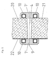
- two shuttering parts 20, 21 of a floor dryer are tightly connected to form a parting line 4, wherein a position compensation parallel to the parting line 4 is possible.
- a sealing strip 7 is in turn arranged over its entire length, each containing a silicone tube 10 to the right and left of the parting line 4.
- On the outside of the sealing joint is additionally between the sealing strip 7 and the shuttering parts 20, 21 nor a cover plate 22 (analogous to the sealing plate 11). Both sealing strips 7 are braced against each other as in the first example by means of a screw 9 and seal the parting line reliably.
Landscapes
- Engineering & Computer Science (AREA)
- Mechanical Engineering (AREA)
- General Engineering & Computer Science (AREA)
- Drying Of Solid Materials (AREA)
- Building Environments (AREA)
- Glass Compositions (AREA)
- Materials For Medical Uses (AREA)
- Sealing Battery Cases Or Jackets (AREA)
- Cleaning Or Drying Semiconductors (AREA)
- Packages (AREA)
Description
- Die Erfindung betrifft eine Dichtungsanordnung für flächige Elemente oder Wandelemente für Trockner von Teigwaren und dergleichen.
- Es ist bekannt, flächige Elemente, zum Beispiel flächige Wandelemente gegen den Durchlass von gasförmigen oder flüssigen aber auch festen Stoffen abzudichten. Dies kann durch Dichtungsmassen oder Klebstoffe erfolgen, die aber zu einer Verschmutzung oder dauerhaften Verbindung der Wandelemente führen. Weiterhin ist es zum Beispiel aus der EP-A-685255 bekannt, die Auslassklappen eines Mischerbehälters mittels Andrückrolle und Dichtschlauch im Betriebszustand abzudichten. Hierbei drückt nach Einschwenken eines Riegels die Andrückrolle gegen die Überlappungsstelle der Klappen. Ein aufblasbarer Dichtschlauch dichtet die jeweils gegenüberliegende Klappenseite ab. Vor dem Öffnen der Klappen muss der Dichtschlauch entlüftet werden.
- Weitere Dichtungsanordnungen sind aus den Dokumenten DE-A-3734818, DE-A-1804043 und US-3175652 bekannt.
- Bei der Anordnung der DE-A-3734818 ist aber kein Lageausgleich parallel zur Ebene der Trennfuge zwischen zwei benachbarten Wandelementen möglich, weil eine starre Verbindung zwischen den Spannelementen der Dichtungselemente und dem starren Rahmen des Trockners vorliegt.
- Die Anordnung der DE-A-1804043 und der US-3175652 verwendet in der Trennfuge angeordnete Dichtungselemente, wobei die Stirnflächen aneinandergrenzender Wandelemente beiderseits der Trennfuge speziell geformte und zu den in der Trennfuge angeordneten Dichtungselementen komplementäre Formationen aufweisen müssen.
- Der Erfindung liegt nun die Aufgabe zugrunde, eine Dichtungsanordnung für flächige Elemente oder Wandelemente, von Teigwarentrocknem zu schaffen, die ein einfaches Verbinden von solchen Elementen bei gleichzeitiger Abdichtung der Verbindungsstelle ermöglichen. Die Lösung dieser Aufgabe erfolgt mit den aufgezeigten Merkmalen des Anspruchs. Vorteilhafte Ausgestaltungen sind in den Unteransprüchen offenbart.
- Kennzeichnend ist hierbei, dass die Verbindung ohne Überlappung der Elemente erfolgt und somit auch die Montage bzw. Demontage mit einfachen Mitteln erfolgen kann. Zudem ist ein Ausgleich von, insbesondere temperaturbedingten Lage-bzw. Massabweichungen möglich.
- Die Erfindung wird nachfolgend an zwei Beispielen an Hand einer Zeichnung näher beschrieben. In der Zeichnung zeigt die
- Figur 1:
- eine Dichtungsanordnung in Form einer Deckenplattendichtung
- Figur 2:
- eine weitere Ausführungsform eines Dichtungsstosses.
- Ein Etagentrockner für Teigwaren, wie er zum Beispiel in der WO 85/00090 oder der nicht vorveröffentlichten DE 10158446.6 der Anmelderin beschrieben ist, weist einzelne Trocknerabteile auf, die wiederum eine äussere Verschalung aufweisen. Die Verschalung besteht aus einzelnen, geformten Platten.
- Im Beispiel ist eine Deckenplatte 1 mit einer weiteren Deckenplatte 2 verbunden (Fig. 1). Die Verbindung erfolgt stumpf an den Stirnflächen 3 bzw. 3'. Dabei ist weder eine dichtende Anlage der Stirnflächen 3 und 3' gegeneinander erforderlich noch eine besondere Feinbearbeitung der Stirnflächen 3, 3', so dass an die Trennfuge 4 keine besonderen Anforderungen gestellt werden.
- Parallel zur Stirnfläche 3, 3' weisen die Platten 1 bzw. 2 jeweils Durchgangs- oder Sacklochbohrungen 5 auf. Auf der Innenseite der Trennfuge 4 ist eine Deckentraverse 6 mit einer ebenen Auflagefläche und Durchgangsbohrungen analog zu den Durchgangsbohrungen 5 der Platten 1, 2 aufgesetzt und auf der Aussenseite eine ebene Dichtleiste 7 mit analogen Durchgangsbohrungen. Auf das Dichtblech kann eine weitere Traverse 8 aufgesetzt sein. Die lagefixierte Befestigung der einzelnen Elemente erfolgt wie abgebildet mittels Verschraubungen 9.
- Die äusseren Bereiche der Dichtleiste 7 sind parallel zum Verlauf der Dichtfuge 4 L-förmig geformt, so dass zusätzlich zwischen Dichtleiste 7 und Platten 1, 2 ein flexibles Dichtelement, hier ein Silikonschlauch 10 eingelegt werden kann.
- Infolge der Verschraubungen 9 ist somit eine ausreichende Abdichtung der Trennfuge 4 gegen den Durchtritt von Dampf oder Gasen gegeben. Im Bedarfsfalls kann jedoch, wie abgebildet noch ein weiteres Dichtblech 11 zwischen der Trennfuge 4 und der Dichtleiste 7 bzw. der Deckentraverse 6 vorgesehen sein.
- Ein Lageausgleich senkrecht zur Ebene der Trennfuge 4 ist möglich.
- Bei einem Dichtungsstoss gemäss Fig. 2 sind zwei Verschalungsteile 20, 21 eines Etagentrockners unter Bildung einer Trennfuge 4 dicht miteinander verbunden, wobei ein Lageausgleich parallel zur Trennfuge 4 möglich ist.
- Sowohl auf der Innenseite als auch auf der Aussenseite der Trennfuge 4 ist wiederum über deren ganze Länge eine Dichtleiste 7 angeordnet, die je einen Silikonschlauch 10 rechts und links von der Trennfuge 4 enthält. Auf der Aussenseite des Dichtungsstosses befindet sich zusätzlich zwischen der Dichtleiste 7 und den Verschalungsteilen 20, 21 noch ein Deckblech 22 (analog zum Dichtblech 11). Beide Dichtleisten 7 werden wie im ersten Beispiel mittels einer Verschraubung 9 gegeneinander verspannt und dichten die Trennfuge zuverlässig ab.
-
- 1.
- Deckenplatte
- 2.
- Deckenplatte
- 3.
- Stirnfläche
- 3'
- Stirnfläche
- 4.
- Trennfuge
- 5.
- Bohrung
- 6.
- Deckentraverse
- 7.
- Dichtleiste
- 7'
- Dichtleiste
- 8
- Traverse
- 9
- Verschraubung
- 10
- Silikonschlauch
- 11
- Dichtblech
- 20
- Verschalung
- 21
- Verschalung
- 22
- Deckblech
Claims (6)
- Dichtungsanordnung für flächige Elemente oder Wandelemente (1,2,20,21) eines eigwarentrockners, deren Stirnflächen (3, 3') unter Bildung einer Trennfuge (4) angeordnet sind, dadurch gekennzeichnet, dass auf die innere und äussere Längsseite der Trennfuge (4) aussen ebene Dichtmittel (6,7,7',8) aufgesetzt sind, die gegeneinander verspannt sind und die einen abdichtenden Abschluss der Trennfuge (4) bilden sowie einen Lageausgleich senkrecht und parallel zur Ebene der Trennfuge (4) ermöglichen, wobei zumindest auf einer Seite zwischen der Wandung der verbundenen, flächigen Elemente (1,2,20,21) und dem ebenen Dichtelement (6,7,7',8) mindestens ein weiteres flexibles Dichtelement (10,11,22) vorgesehen ist.
- Dichtungsanordnung nach Anspruch 1, dadurch gekennzeichnet, dass die, die Trennfuge (4) erzeugenden Elemente parallel zur Trennfuge (4) jeweils Durchgangs- oder Sacklochbohrungen (5) aufweisen und die beidseifig im Bereich der Längsseiten der Trennfuge (4) aufgesetzten Dichtelemente (6,7,7',8) Durchgangsbohrungen aufweisen, durch die Vertündungsmittel (9) geführt sind.
- Dichtungsanordnung nach Anspruch 1 oder 2, dadurch gekennzeichnet, dass die Verbindungsmittel Verschraubungen (9) sind.
- Dichtungsanordnung nach mindestens einem der Ansprüche 1 bis 3, dadurch gekennzeichnet, dass das weitere Dichtelement (10,11,22) ein ebenes Element ist.
- Dichtungsanordnung nach Anspruch 2, dadurch gekennzeichnet, dass jedes flächige Element oder Wandelement (1,2,20,21) mindestens zwei Bohrungen (5) aufweist.
- Dichtungsanordnung nach mindestens einem der Ansprüche 1 bis 4, dadurch gekennzeichnet, dass ein flexibles Dichtelement (10) rechts und links von der Trennfuge (4) angeordnet ist.
Applications Claiming Priority (3)
| Application Number | Priority Date | Filing Date | Title |
|---|---|---|---|
| DE10215181 | 2002-04-05 | ||
| DE10215181A DE10215181A1 (de) | 2002-04-05 | 2002-04-05 | Dichtungsanordnung |
| PCT/CH2003/000123 WO2003085342A1 (de) | 2002-04-05 | 2003-02-19 | Dichtungsanordnung |
Publications (2)
| Publication Number | Publication Date |
|---|---|
| EP1492989A1 EP1492989A1 (de) | 2005-01-05 |
| EP1492989B1 true EP1492989B1 (de) | 2006-06-21 |
Family
ID=28458611
Family Applications (1)
| Application Number | Title | Priority Date | Filing Date |
|---|---|---|---|
| EP03701435A Expired - Lifetime EP1492989B1 (de) | 2002-04-05 | 2003-02-19 | Dichtungsanordnung |
Country Status (8)
| Country | Link |
|---|---|
| EP (1) | EP1492989B1 (de) |
| CN (1) | CN1643321B (de) |
| AT (1) | ATE331195T1 (de) |
| AU (1) | AU2003203129A1 (de) |
| BR (1) | BR0308417B1 (de) |
| DE (2) | DE10215181A1 (de) |
| RU (1) | RU2325604C2 (de) |
| WO (1) | WO2003085342A1 (de) |
Family Cites Families (13)
| Publication number | Priority date | Publication date | Assignee | Title |
|---|---|---|---|---|
| US1741342A (en) * | 1928-07-20 | 1929-12-31 | Proctor & Schwartz Inc | Panel for driers |
| DE744357C (de) * | 1940-12-17 | 1944-01-14 | Benno Schilde Maschb Ag | Geruestaufbau fuer waerme- oder kaelteisolierende Doppelwaende von Trocken-, Heiz- und Kuehlanlagen |
| CH335841A (de) * | 1954-12-17 | 1959-01-31 | Maschf Augsburg Nuernberg Ag | Einrichtung zum Verbinden vorgefertigter Bauteile |
| US3175652A (en) * | 1960-12-14 | 1965-03-30 | Means for interconnecting adjacent wall sections | |
| DE1804043A1 (de) * | 1968-10-19 | 1970-12-03 | Buettner Shilde Haas Ag | Gehaeuse fuer Trockner u.dgl.mit durch ein Rahmenwerk gestuetzten Doppelwaenden |
| EP0011239B2 (de) * | 1978-11-09 | 1989-03-15 | G + H MONTAGE GmbH | Schallschutzwand |
| US4296540A (en) * | 1978-12-21 | 1981-10-27 | Burley Industries, Inc. | Method for sealing a dryer |
| DE3400300C2 (de) | 1983-06-24 | 1986-01-23 | Gebrüder Bühler AG, Uzwil | Verfahren zur Herstellung von langen Teigwaren und Vorrichtung zur Durchführung eines solchen Verfahrens |
| DE3734818A1 (de) * | 1987-10-14 | 1989-04-27 | Rheinhold & Mahla Gmbh | Trockenkanal, insbesondere fuer textile kunststoffasern |
| CN2092075U (zh) * | 1991-01-31 | 1992-01-01 | 张弘基 | 一种结构简单的节能型振动干燥机 |
| CH689667A5 (de) | 1994-04-29 | 1999-08-13 | Buehler Ag | Chargenmischer. |
| US6220651B1 (en) * | 1996-09-12 | 2001-04-24 | Wabash Technology Corporation | Composite joint configuration |
| DE10158446A1 (de) | 2001-11-30 | 2003-06-12 | Buehler Ag | Trockner für die Durchlauftrocknung von Lebensmittelprodukten |
-
2002
- 2002-04-05 DE DE10215181A patent/DE10215181A1/de not_active Withdrawn
-
2003
- 2003-02-19 DE DE50303952T patent/DE50303952D1/de not_active Expired - Lifetime
- 2003-02-19 BR BRPI0308417-5A patent/BR0308417B1/pt not_active IP Right Cessation
- 2003-02-19 WO PCT/CH2003/000123 patent/WO2003085342A1/de not_active Ceased
- 2003-02-19 AU AU2003203129A patent/AU2003203129A1/en not_active Abandoned
- 2003-02-19 AT AT03701435T patent/ATE331195T1/de not_active IP Right Cessation
- 2003-02-19 EP EP03701435A patent/EP1492989B1/de not_active Expired - Lifetime
- 2003-02-19 RU RU2004132227/06A patent/RU2325604C2/ru active
- 2003-02-19 CN CN03806778.1A patent/CN1643321B/zh not_active Expired - Lifetime
Also Published As
| Publication number | Publication date |
|---|---|
| RU2325604C2 (ru) | 2008-05-27 |
| DE50303952D1 (de) | 2006-08-03 |
| ATE331195T1 (de) | 2006-07-15 |
| WO2003085342A1 (de) | 2003-10-16 |
| EP1492989A1 (de) | 2005-01-05 |
| BR0308417B1 (pt) | 2013-02-19 |
| CN1643321A (zh) | 2005-07-20 |
| AU2003203129A1 (en) | 2003-10-20 |
| CN1643321B (zh) | 2010-10-06 |
| DE10215181A1 (de) | 2003-10-23 |
| BR0308417A (pt) | 2005-01-18 |
| RU2004132227A (ru) | 2005-04-27 |
Similar Documents
| Publication | Publication Date | Title |
|---|---|---|
| DE1956170A1 (de) | Verbindungen fuer Platten | |
| EP0355270A1 (de) | Dichtung für eine Durchführung für Leitungen, wie Kabel, Rohre oder dergl., durch eine Wandöffnung | |
| DE3447901A1 (de) | Von der decke eines raumes abhaengbare modulare rahmenanordnung zur aufnahme von filtern mit fluiddichtung fuer reinraumdecken | |
| DE102012209591B4 (de) | Membranplatte, Filterplatte, Filterpresse und Verwendung einer Filterpresse | |
| DE10135055C1 (de) | Etagenpresse | |
| EP1492989B1 (de) | Dichtungsanordnung | |
| DE19901418A1 (de) | Im Falzraum einer Fassade oder eines Lichtdaches anzuordnendes Dichtungsprofil | |
| DE2916800C3 (de) | Anschluß eines Riegels an einen Pfosten einer Rahmenkonstruktion, insb. für vorgehängte Füllelemente, wie Scheiben, Paneele o.dgl. | |
| DE10252922B3 (de) | Membranfilterpresse | |
| DE19905674C1 (de) | Filterpresse mit horizontal angeordneten Filterplatten | |
| DE3103925A1 (de) | Gelenkverbindung von zur abdeckung von schwimmbaedern dienenden hohlkammerplatten | |
| EP0301129A2 (de) | Filterwand/-decke für reinraumtechnische Anlagen | |
| DE946261C (de) | Anordnung zum Zusammenfuegen von Platten zu doppelten Waenden, Tueren u. dgl. | |
| DE3935780A1 (de) | Plattenstruktur | |
| DE19961396A1 (de) | Vorrichtung für die Abdichtung einer Öffnung, insbesondere einer Bauwerksöffnung | |
| EP3724555B1 (de) | Lüftungsgerät und verfahren zu dessen montage und demontage | |
| DE102006034146A1 (de) | Ein- oder Mehretagenpresse zur Herstellung von Werkstoffplatten | |
| DE2338803A1 (de) | Kupplung fuer fluessigkeits- und gasrohrleitungen | |
| DE3734818A1 (de) | Trockenkanal, insbesondere fuer textile kunststoffasern | |
| DE2827881C2 (de) | Dichtung von Spalten an einer wärmegedämmten Rohrleitung | |
| EP0912423A2 (de) | Verbindungsbereich zweier einander dicht zugeordneter, voneinander lösbarer teile, insbesondere an einem auffangbehälter für verunreinigende flüssigkeit wie isolierflüssigkeit eines transformators | |
| DE102013020394B4 (de) | Gehäuse zum Einbau von Bildschirmen und/oder Bedienfeldern | |
| DE3600375A1 (de) | Vorrichtung zur abdichtung eines ringraumes | |
| DE202022100036U1 (de) | Anschlussvorrichtung | |
| DE2265166C3 (de) | Durchlauftrockner für Bahnmaterialien |
Legal Events
| Date | Code | Title | Description |
|---|---|---|---|
| PUAI | Public reference made under article 153(3) epc to a published international application that has entered the european phase |
Free format text: ORIGINAL CODE: 0009012 |
|
| 17P | Request for examination filed |
Effective date: 20040713 |
|
| AK | Designated contracting states |
Kind code of ref document: A1 Designated state(s): AT BE BG CH CY CZ DE DK EE ES FI FR GB GR HU IE IT LI LU MC NL PT SE SI SK TR |
|
| AX | Request for extension of the european patent |
Extension state: AL LT LV MK RO |
|
| GRAP | Despatch of communication of intention to grant a patent |
Free format text: ORIGINAL CODE: EPIDOSNIGR1 |
|
| GRAS | Grant fee paid |
Free format text: ORIGINAL CODE: EPIDOSNIGR3 |
|
| GRAA | (expected) grant |
Free format text: ORIGINAL CODE: 0009210 |
|
| AK | Designated contracting states |
Kind code of ref document: B1 Designated state(s): AT BE BG CH CY CZ DE DK EE ES FI FR GB GR HU IE IT LI LU MC NL PT SE SI SK TR |
|
| PG25 | Lapsed in a contracting state [announced via postgrant information from national office to epo] |
Ref country code: NL Free format text: LAPSE BECAUSE OF FAILURE TO SUBMIT A TRANSLATION OF THE DESCRIPTION OR TO PAY THE FEE WITHIN THE PRESCRIBED TIME-LIMIT Effective date: 20060621 Ref country code: SI Free format text: LAPSE BECAUSE OF FAILURE TO SUBMIT A TRANSLATION OF THE DESCRIPTION OR TO PAY THE FEE WITHIN THE PRESCRIBED TIME-LIMIT Effective date: 20060621 Ref country code: GB Free format text: LAPSE BECAUSE OF FAILURE TO SUBMIT A TRANSLATION OF THE DESCRIPTION OR TO PAY THE FEE WITHIN THE PRESCRIBED TIME-LIMIT Effective date: 20060621 Ref country code: IT Free format text: LAPSE BECAUSE OF FAILURE TO SUBMIT A TRANSLATION OF THE DESCRIPTION OR TO PAY THE FEE WITHIN THE PRESCRIBED TIME-LIMIT;WARNING: LAPSES OF ITALIAN PATENTS WITH EFFECTIVE DATE BEFORE 2007 MAY HAVE OCCURRED AT ANY TIME BEFORE 2007. THE CORRECT EFFECTIVE DATE MAY BE DIFFERENT FROM THE ONE RECORDED. Effective date: 20060621 Ref country code: SK Free format text: LAPSE BECAUSE OF FAILURE TO SUBMIT A TRANSLATION OF THE DESCRIPTION OR TO PAY THE FEE WITHIN THE PRESCRIBED TIME-LIMIT Effective date: 20060621 Ref country code: IE Free format text: LAPSE BECAUSE OF FAILURE TO SUBMIT A TRANSLATION OF THE DESCRIPTION OR TO PAY THE FEE WITHIN THE PRESCRIBED TIME-LIMIT Effective date: 20060621 Ref country code: FI Free format text: LAPSE BECAUSE OF FAILURE TO SUBMIT A TRANSLATION OF THE DESCRIPTION OR TO PAY THE FEE WITHIN THE PRESCRIBED TIME-LIMIT Effective date: 20060621 Ref country code: CZ Free format text: LAPSE BECAUSE OF FAILURE TO SUBMIT A TRANSLATION OF THE DESCRIPTION OR TO PAY THE FEE WITHIN THE PRESCRIBED TIME-LIMIT Effective date: 20060621 |
|
| REG | Reference to a national code |
Ref country code: GB Ref legal event code: FG4D Free format text: NOT ENGLISH |
|
| REG | Reference to a national code |
Ref country code: CH Ref legal event code: EP |
|
| REG | Reference to a national code |
Ref country code: IE Ref legal event code: FG4D Free format text: LANGUAGE OF EP DOCUMENT: GERMAN |
|
| REF | Corresponds to: |
Ref document number: 50303952 Country of ref document: DE Date of ref document: 20060803 Kind code of ref document: P |
|
| PG25 | Lapsed in a contracting state [announced via postgrant information from national office to epo] |
Ref country code: SE Free format text: LAPSE BECAUSE OF FAILURE TO SUBMIT A TRANSLATION OF THE DESCRIPTION OR TO PAY THE FEE WITHIN THE PRESCRIBED TIME-LIMIT Effective date: 20060921 Ref country code: DK Free format text: LAPSE BECAUSE OF FAILURE TO SUBMIT A TRANSLATION OF THE DESCRIPTION OR TO PAY THE FEE WITHIN THE PRESCRIBED TIME-LIMIT Effective date: 20060921 |
|
| PG25 | Lapsed in a contracting state [announced via postgrant information from national office to epo] |
Ref country code: ES Free format text: LAPSE BECAUSE OF FAILURE TO SUBMIT A TRANSLATION OF THE DESCRIPTION OR TO PAY THE FEE WITHIN THE PRESCRIBED TIME-LIMIT Effective date: 20061002 |
|
| PG25 | Lapsed in a contracting state [announced via postgrant information from national office to epo] |
Ref country code: PT Free format text: LAPSE BECAUSE OF FAILURE TO SUBMIT A TRANSLATION OF THE DESCRIPTION OR TO PAY THE FEE WITHIN THE PRESCRIBED TIME-LIMIT Effective date: 20061121 |
|
| NLV1 | Nl: lapsed or annulled due to failure to fulfill the requirements of art. 29p and 29m of the patents act | ||
| ET | Fr: translation filed | ||
| GBV | Gb: ep patent (uk) treated as always having been void in accordance with gb section 77(7)/1977 [no translation filed] |
Effective date: 20060621 |
|
| REG | Reference to a national code |
Ref country code: IE Ref legal event code: FD4D |
|
| PG25 | Lapsed in a contracting state [announced via postgrant information from national office to epo] |
Ref country code: MC Free format text: LAPSE BECAUSE OF NON-PAYMENT OF DUE FEES Effective date: 20070228 |
|
| PLBE | No opposition filed within time limit |
Free format text: ORIGINAL CODE: 0009261 |
|
| STAA | Information on the status of an ep patent application or granted ep patent |
Free format text: STATUS: NO OPPOSITION FILED WITHIN TIME LIMIT |
|
| 26N | No opposition filed |
Effective date: 20070322 |
|
| BERE | Be: lapsed |
Owner name: BUHLER A.G. Effective date: 20070228 |
|
| PG25 | Lapsed in a contracting state [announced via postgrant information from national office to epo] |
Ref country code: BE Free format text: LAPSE BECAUSE OF NON-PAYMENT OF DUE FEES Effective date: 20070228 |
|
| PG25 | Lapsed in a contracting state [announced via postgrant information from national office to epo] |
Ref country code: GR Free format text: LAPSE BECAUSE OF FAILURE TO SUBMIT A TRANSLATION OF THE DESCRIPTION OR TO PAY THE FEE WITHIN THE PRESCRIBED TIME-LIMIT Effective date: 20060922 |
|
| PG25 | Lapsed in a contracting state [announced via postgrant information from national office to epo] |
Ref country code: BG Free format text: LAPSE BECAUSE OF FAILURE TO SUBMIT A TRANSLATION OF THE DESCRIPTION OR TO PAY THE FEE WITHIN THE PRESCRIBED TIME-LIMIT Effective date: 20060921 Ref country code: AT Free format text: LAPSE BECAUSE OF NON-PAYMENT OF DUE FEES Effective date: 20070219 |
|
| PG25 | Lapsed in a contracting state [announced via postgrant information from national office to epo] |
Ref country code: EE Free format text: LAPSE BECAUSE OF FAILURE TO SUBMIT A TRANSLATION OF THE DESCRIPTION OR TO PAY THE FEE WITHIN THE PRESCRIBED TIME-LIMIT Effective date: 20060621 |
|
| PG25 | Lapsed in a contracting state [announced via postgrant information from national office to epo] |
Ref country code: CY Free format text: LAPSE BECAUSE OF FAILURE TO SUBMIT A TRANSLATION OF THE DESCRIPTION OR TO PAY THE FEE WITHIN THE PRESCRIBED TIME-LIMIT Effective date: 20060621 Ref country code: LU Free format text: LAPSE BECAUSE OF NON-PAYMENT OF DUE FEES Effective date: 20070219 |
|
| PG25 | Lapsed in a contracting state [announced via postgrant information from national office to epo] |
Ref country code: HU Free format text: LAPSE BECAUSE OF FAILURE TO SUBMIT A TRANSLATION OF THE DESCRIPTION OR TO PAY THE FEE WITHIN THE PRESCRIBED TIME-LIMIT Effective date: 20061222 Ref country code: TR Free format text: LAPSE BECAUSE OF FAILURE TO SUBMIT A TRANSLATION OF THE DESCRIPTION OR TO PAY THE FEE WITHIN THE PRESCRIBED TIME-LIMIT Effective date: 20060621 |
|
| PGFP | Annual fee paid to national office [announced via postgrant information from national office to epo] |
Ref country code: CH Payment date: 20140220 Year of fee payment: 12 Ref country code: DE Payment date: 20140220 Year of fee payment: 12 |
|
| PGFP | Annual fee paid to national office [announced via postgrant information from national office to epo] |
Ref country code: FR Payment date: 20140218 Year of fee payment: 12 |
|
| REG | Reference to a national code |
Ref country code: DE Ref legal event code: R119 Ref document number: 50303952 Country of ref document: DE |
|
| REG | Reference to a national code |
Ref country code: CH Ref legal event code: PL |
|
| PG25 | Lapsed in a contracting state [announced via postgrant information from national office to epo] |
Ref country code: LI Free format text: LAPSE BECAUSE OF NON-PAYMENT OF DUE FEES Effective date: 20150228 Ref country code: CH Free format text: LAPSE BECAUSE OF NON-PAYMENT OF DUE FEES Effective date: 20150228 |
|
| REG | Reference to a national code |
Ref country code: FR Ref legal event code: ST Effective date: 20151030 |
|
| PG25 | Lapsed in a contracting state [announced via postgrant information from national office to epo] |
Ref country code: DE Free format text: LAPSE BECAUSE OF NON-PAYMENT OF DUE FEES Effective date: 20150901 |
|
| PG25 | Lapsed in a contracting state [announced via postgrant information from national office to epo] |
Ref country code: FR Free format text: LAPSE BECAUSE OF NON-PAYMENT OF DUE FEES Effective date: 20150302 |
|
| PGFP | Annual fee paid to national office [announced via postgrant information from national office to epo] |
Ref country code: IT Payment date: 20220228 Year of fee payment: 20 |
|
| P01 | Opt-out of the competence of the unified patent court (upc) registered |
Effective date: 20230523 |