EP1492852B1 - Sauber ablösbare bänder und deren herstellung - Google Patents
Sauber ablösbare bänder und deren herstellung Download PDFInfo
- Publication number
- EP1492852B1 EP1492852B1 EP03746533A EP03746533A EP1492852B1 EP 1492852 B1 EP1492852 B1 EP 1492852B1 EP 03746533 A EP03746533 A EP 03746533A EP 03746533 A EP03746533 A EP 03746533A EP 1492852 B1 EP1492852 B1 EP 1492852B1
- Authority
- EP
- European Patent Office
- Prior art keywords
- tape
- adhesive
- adhesive layer
- layer
- core layer
- Prior art date
- Legal status (The legal status is an assumption and is not a legal conclusion. Google has not performed a legal analysis and makes no representation as to the accuracy of the status listed.)
- Expired - Lifetime
Links
- 238000000034 method Methods 0.000 title claims description 32
- 238000004519 manufacturing process Methods 0.000 title description 13
- 239000012790 adhesive layer Substances 0.000 claims abstract description 109
- 239000012792 core layer Substances 0.000 claims abstract description 104
- 239000003063 flame retardant Substances 0.000 claims abstract description 104
- 239000004820 Pressure-sensitive adhesive Substances 0.000 claims abstract description 42
- 239000010410 layer Substances 0.000 claims abstract description 36
- 229910052787 antimony Inorganic materials 0.000 claims abstract description 8
- WATWJIUSRGPENY-UHFFFAOYSA-N antimony atom Chemical compound [Sb] WATWJIUSRGPENY-UHFFFAOYSA-N 0.000 claims abstract description 8
- 230000001070 adhesive effect Effects 0.000 claims description 157
- 239000000853 adhesive Substances 0.000 claims description 152
- 229920001410 Microfiber Polymers 0.000 claims description 70
- 239000003658 microfiber Substances 0.000 claims description 70
- 239000000463 material Substances 0.000 claims description 66
- 239000000758 substrate Substances 0.000 claims description 56
- 239000000203 mixture Substances 0.000 claims description 53
- 238000012360 testing method Methods 0.000 claims description 43
- 229920005989 resin Polymers 0.000 claims description 42
- 239000011347 resin Substances 0.000 claims description 42
- 229920001577 copolymer Polymers 0.000 claims description 20
- 229920001296 polysiloxane Polymers 0.000 claims description 20
- 229920001971 elastomer Polymers 0.000 claims description 18
- 239000005060 rubber Substances 0.000 claims description 15
- 230000003014 reinforcing effect Effects 0.000 claims description 14
- 239000000835 fiber Substances 0.000 claims description 13
- 239000012779 reinforcing material Substances 0.000 claims description 12
- 229920001400 block copolymer Polymers 0.000 claims description 9
- 229920000098 polyolefin Polymers 0.000 claims description 9
- 229920001519 homopolymer Polymers 0.000 claims description 8
- 238000011084 recovery Methods 0.000 claims description 7
- 239000010935 stainless steel Substances 0.000 claims description 7
- 229910001220 stainless steel Inorganic materials 0.000 claims description 7
- 229920002725 thermoplastic elastomer Polymers 0.000 claims description 7
- 229920002635 polyurethane Polymers 0.000 claims description 6
- 239000004814 polyurethane Substances 0.000 claims description 6
- 229920001897 terpolymer Polymers 0.000 claims description 5
- 229920006029 tetra-polymer Polymers 0.000 claims description 5
- 239000003522 acrylic cement Substances 0.000 claims description 4
- 229920000058 polyacrylate Polymers 0.000 claims description 4
- 239000001654 beetroot red Substances 0.000 claims description 3
- ZUOUZKKEUPVFJK-UHFFFAOYSA-N diphenyl Chemical group C1=CC=CC=C1C1=CC=CC=C1 ZUOUZKKEUPVFJK-UHFFFAOYSA-N 0.000 claims description 3
- 210000004177 elastic tissue Anatomy 0.000 claims description 3
- 230000003287 optical effect Effects 0.000 claims description 3
- 229920001281 polyalkylene Polymers 0.000 claims description 3
- 235000010290 biphenyl Nutrition 0.000 abstract description 7
- 150000004074 biphenyls Chemical class 0.000 abstract description 7
- 125000002467 phosphate group Chemical class [H]OP(=O)(O[H])O[*] 0.000 abstract 1
- 239000011162 core material Substances 0.000 description 31
- -1 hot melt coating Substances 0.000 description 22
- 229920000642 polymer Polymers 0.000 description 22
- 238000002156 mixing Methods 0.000 description 19
- 239000000654 additive Substances 0.000 description 16
- 239000002952 polymeric resin Substances 0.000 description 14
- 229920003002 synthetic resin Polymers 0.000 description 14
- BHYQWBKCXBXPKM-UHFFFAOYSA-N tris[3-bromo-2,2-bis(bromomethyl)propyl] phosphate Chemical compound BrCC(CBr)(CBr)COP(=O)(OCC(CBr)(CBr)CBr)OCC(CBr)(CBr)CBr BHYQWBKCXBXPKM-UHFFFAOYSA-N 0.000 description 14
- 239000011888 foil Substances 0.000 description 13
- 239000000178 monomer Substances 0.000 description 12
- 230000008569 process Effects 0.000 description 12
- 238000001125 extrusion Methods 0.000 description 11
- 239000000126 substance Substances 0.000 description 11
- 238000010276 construction Methods 0.000 description 10
- 238000002844 melting Methods 0.000 description 10
- 230000008018 melting Effects 0.000 description 10
- 230000005855 radiation Effects 0.000 description 10
- NIXOWILDQLNWCW-UHFFFAOYSA-M Acrylate Chemical compound [O-]C(=O)C=C NIXOWILDQLNWCW-UHFFFAOYSA-M 0.000 description 9
- 238000010998 test method Methods 0.000 description 9
- 239000011248 coating agent Substances 0.000 description 8
- 238000000576 coating method Methods 0.000 description 8
- 238000009472 formulation Methods 0.000 description 8
- 238000002360 preparation method Methods 0.000 description 8
- 229910052782 aluminium Inorganic materials 0.000 description 7
- XAGFODPZIPBFFR-UHFFFAOYSA-N aluminium Chemical compound [Al] XAGFODPZIPBFFR-UHFFFAOYSA-N 0.000 description 7
- GOXQRTZXKQZDDN-UHFFFAOYSA-N 2-Ethylhexyl acrylate Chemical compound CCCCC(CC)COC(=O)C=C GOXQRTZXKQZDDN-UHFFFAOYSA-N 0.000 description 6
- 239000005977 Ethylene Substances 0.000 description 6
- NIXOWILDQLNWCW-UHFFFAOYSA-N acrylic acid group Chemical group C(C=C)(=O)O NIXOWILDQLNWCW-UHFFFAOYSA-N 0.000 description 6
- 239000002998 adhesive polymer Substances 0.000 description 6
- 239000011521 glass Substances 0.000 description 6
- 229920000728 polyester Polymers 0.000 description 6
- KWVGIHKZDCUPEU-UHFFFAOYSA-N 2,2-dimethoxy-2-phenylacetophenone Chemical compound C=1C=CC=CC=1C(OC)(OC)C(=O)C1=CC=CC=C1 KWVGIHKZDCUPEU-UHFFFAOYSA-N 0.000 description 5
- 239000004743 Polypropylene Substances 0.000 description 5
- 238000004132 cross linking Methods 0.000 description 5
- 239000000123 paper Substances 0.000 description 5
- 229920006267 polyester film Polymers 0.000 description 5
- 229920001155 polypropylene Polymers 0.000 description 5
- 230000004580 weight loss Effects 0.000 description 5
- RNFJDJUURJAICM-UHFFFAOYSA-N 2,2,4,4,6,6-hexaphenoxy-1,3,5-triaza-2$l^{5},4$l^{5},6$l^{5}-triphosphacyclohexa-1,3,5-triene Chemical compound N=1P(OC=2C=CC=CC=2)(OC=2C=CC=CC=2)=NP(OC=2C=CC=CC=2)(OC=2C=CC=CC=2)=NP=1(OC=1C=CC=CC=1)OC1=CC=CC=C1 RNFJDJUURJAICM-UHFFFAOYSA-N 0.000 description 4
- 239000004114 Ammonium polyphosphate Substances 0.000 description 4
- 229920000877 Melamine resin Polymers 0.000 description 4
- PPBRXRYQALVLMV-UHFFFAOYSA-N Styrene Chemical compound C=CC1=CC=CC=C1 PPBRXRYQALVLMV-UHFFFAOYSA-N 0.000 description 4
- 235000019826 ammonium polyphosphate Nutrition 0.000 description 4
- 229920001276 ammonium polyphosphate Polymers 0.000 description 4
- ADCOVFLJGNWWNZ-UHFFFAOYSA-N antimony trioxide Chemical compound O=[Sb]O[Sb]=O ADCOVFLJGNWWNZ-UHFFFAOYSA-N 0.000 description 4
- 230000033228 biological regulation Effects 0.000 description 4
- 239000002131 composite material Substances 0.000 description 4
- WHHGLZMJPXIBIX-UHFFFAOYSA-N decabromodiphenyl ether Chemical compound BrC1=C(Br)C(Br)=C(Br)C(Br)=C1OC1=C(Br)C(Br)=C(Br)C(Br)=C1Br WHHGLZMJPXIBIX-UHFFFAOYSA-N 0.000 description 4
- 239000004744 fabric Substances 0.000 description 4
- 230000009477 glass transition Effects 0.000 description 4
- 238000011065 in-situ storage Methods 0.000 description 4
- 239000002655 kraft paper Substances 0.000 description 4
- 230000000873 masking effect Effects 0.000 description 4
- 239000000155 melt Substances 0.000 description 4
- 239000004005 microsphere Substances 0.000 description 4
- 150000003013 phosphoric acid derivatives Chemical class 0.000 description 4
- 238000012545 processing Methods 0.000 description 4
- 230000003068 static effect Effects 0.000 description 4
- 238000012546 transfer Methods 0.000 description 4
- SMZOUWXMTYCWNB-UHFFFAOYSA-N 2-(2-methoxy-5-methylphenyl)ethanamine Chemical compound COC1=CC=C(C)C=C1CCN SMZOUWXMTYCWNB-UHFFFAOYSA-N 0.000 description 3
- IUNVCWLKOOCPIT-UHFFFAOYSA-N 6-methylheptylsulfanyl 2-hydroxyacetate Chemical compound CC(C)CCCCCSOC(=O)CO IUNVCWLKOOCPIT-UHFFFAOYSA-N 0.000 description 3
- 239000004604 Blowing Agent Substances 0.000 description 3
- 229920001875 Ebonite Polymers 0.000 description 3
- VGGSQFUCUMXWEO-UHFFFAOYSA-N Ethene Chemical compound C=C VGGSQFUCUMXWEO-UHFFFAOYSA-N 0.000 description 3
- CERQOIWHTDAKMF-UHFFFAOYSA-M Methacrylate Chemical compound CC(=C)C([O-])=O CERQOIWHTDAKMF-UHFFFAOYSA-M 0.000 description 3
- OAICVXFJPJFONN-UHFFFAOYSA-N Phosphorus Chemical compound [P] OAICVXFJPJFONN-UHFFFAOYSA-N 0.000 description 3
- XTXRWKRVRITETP-UHFFFAOYSA-N Vinyl acetate Chemical compound CC(=O)OC=C XTXRWKRVRITETP-UHFFFAOYSA-N 0.000 description 3
- 239000002253 acid Substances 0.000 description 3
- 239000002318 adhesion promoter Substances 0.000 description 3
- 230000032683 aging Effects 0.000 description 3
- 239000002216 antistatic agent Substances 0.000 description 3
- 230000015572 biosynthetic process Effects 0.000 description 3
- 125000004432 carbon atom Chemical group C* 0.000 description 3
- 230000015556 catabolic process Effects 0.000 description 3
- 239000003795 chemical substances by application Substances 0.000 description 3
- 238000006731 degradation reaction Methods 0.000 description 3
- 239000000806 elastomer Substances 0.000 description 3
- 238000010894 electron beam technology Methods 0.000 description 3
- 239000012943 hotmelt Substances 0.000 description 3
- 238000004898 kneading Methods 0.000 description 3
- 238000003475 lamination Methods 0.000 description 3
- 230000007246 mechanism Effects 0.000 description 3
- JDSHMPZPIAZGSV-UHFFFAOYSA-N melamine Chemical compound NC1=NC(N)=NC(N)=N1 JDSHMPZPIAZGSV-UHFFFAOYSA-N 0.000 description 3
- 230000000704 physical effect Effects 0.000 description 3
- 238000005096 rolling process Methods 0.000 description 3
- 229920006126 semicrystalline polymer Polymers 0.000 description 3
- ACRQLFSHISNWRY-UHFFFAOYSA-N 1,2,3,4,5-pentabromo-6-phenoxybenzene Chemical compound BrC1=C(Br)C(Br)=C(Br)C(Br)=C1OC1=CC=CC=C1 ACRQLFSHISNWRY-UHFFFAOYSA-N 0.000 description 2
- ORYGKUIDIMIRNN-UHFFFAOYSA-N 1,2,3,4-tetrabromo-5-(2,3,4,5-tetrabromophenoxy)benzene Chemical compound BrC1=C(Br)C(Br)=CC(OC=2C(=C(Br)C(Br)=C(Br)C=2)Br)=C1Br ORYGKUIDIMIRNN-UHFFFAOYSA-N 0.000 description 2
- DXPPIEDUBFUSEZ-UHFFFAOYSA-N 6-methylheptyl prop-2-enoate Chemical compound CC(C)CCCCCOC(=O)C=C DXPPIEDUBFUSEZ-UHFFFAOYSA-N 0.000 description 2
- VTYYLEPIZMXCLO-UHFFFAOYSA-L Calcium carbonate Chemical compound [Ca+2].[O-]C([O-])=O VTYYLEPIZMXCLO-UHFFFAOYSA-L 0.000 description 2
- 239000004593 Epoxy Substances 0.000 description 2
- LYCAIKOWRPUZTN-UHFFFAOYSA-N Ethylene glycol Chemical compound OCCO LYCAIKOWRPUZTN-UHFFFAOYSA-N 0.000 description 2
- 239000004831 Hot glue Substances 0.000 description 2
- CERQOIWHTDAKMF-UHFFFAOYSA-N Methacrylic acid Chemical compound CC(=C)C(O)=O CERQOIWHTDAKMF-UHFFFAOYSA-N 0.000 description 2
- BAPJBEWLBFYGME-UHFFFAOYSA-N Methyl acrylate Chemical compound COC(=O)C=C BAPJBEWLBFYGME-UHFFFAOYSA-N 0.000 description 2
- 239000004698 Polyethylene Substances 0.000 description 2
- 229920000388 Polyphosphate Polymers 0.000 description 2
- VYPSYNLAJGMNEJ-UHFFFAOYSA-N Silicium dioxide Chemical compound O=[Si]=O VYPSYNLAJGMNEJ-UHFFFAOYSA-N 0.000 description 2
- 230000000996 additive effect Effects 0.000 description 2
- 125000001931 aliphatic group Chemical group 0.000 description 2
- LFVGISIMTYGQHF-UHFFFAOYSA-N ammonium dihydrogen phosphate Chemical compound [NH4+].OP(O)([O-])=O LFVGISIMTYGQHF-UHFFFAOYSA-N 0.000 description 2
- 229910000387 ammonium dihydrogen phosphate Inorganic materials 0.000 description 2
- 239000004599 antimicrobial Substances 0.000 description 2
- 239000003963 antioxidant agent Substances 0.000 description 2
- 125000003118 aryl group Chemical group 0.000 description 2
- 125000001246 bromo group Chemical group Br* 0.000 description 2
- 230000001143 conditioned effect Effects 0.000 description 2
- 230000007423 decrease Effects 0.000 description 2
- 239000000975 dye Substances 0.000 description 2
- 230000007613 environmental effect Effects 0.000 description 2
- 229920005648 ethylene methacrylic acid copolymer Polymers 0.000 description 2
- 239000000945 filler Substances 0.000 description 2
- 238000009413 insulation Methods 0.000 description 2
- 229920000554 ionomer Polymers 0.000 description 2
- 238000005304 joining Methods 0.000 description 2
- PBOSTUDLECTMNL-UHFFFAOYSA-N lauryl acrylate Chemical compound CCCCCCCCCCCCOC(=O)C=C PBOSTUDLECTMNL-UHFFFAOYSA-N 0.000 description 2
- 229920000092 linear low density polyethylene Polymers 0.000 description 2
- 239000004707 linear low-density polyethylene Substances 0.000 description 2
- 239000011159 matrix material Substances 0.000 description 2
- 150000002734 metacrylic acid derivatives Chemical class 0.000 description 2
- 238000012986 modification Methods 0.000 description 2
- 230000004048 modification Effects 0.000 description 2
- JKQOBWVOAYFWKG-UHFFFAOYSA-N molybdenum trioxide Chemical compound O=[Mo](=O)=O JKQOBWVOAYFWKG-UHFFFAOYSA-N 0.000 description 2
- 239000006012 monoammonium phosphate Substances 0.000 description 2
- 235000019837 monoammonium phosphate Nutrition 0.000 description 2
- 239000002105 nanoparticle Substances 0.000 description 2
- 229920003052 natural elastomer Polymers 0.000 description 2
- 229920001194 natural rubber Polymers 0.000 description 2
- 229910052760 oxygen Inorganic materials 0.000 description 2
- 239000002245 particle Substances 0.000 description 2
- GUSFEBGYPWJUSS-UHFFFAOYSA-N pentaazanium;[oxido(phosphonatooxy)phosphoryl] phosphate Chemical compound [NH4+].[NH4+].[NH4+].[NH4+].[NH4+].[O-]P([O-])(=O)OP([O-])(=O)OP([O-])([O-])=O GUSFEBGYPWJUSS-UHFFFAOYSA-N 0.000 description 2
- PNJWIWWMYCMZRO-UHFFFAOYSA-N pent‐4‐en‐2‐one Natural products CC(=O)CC=C PNJWIWWMYCMZRO-UHFFFAOYSA-N 0.000 description 2
- XFZRQAZGUOTJCS-UHFFFAOYSA-N phosphoric acid;1,3,5-triazine-2,4,6-triamine Chemical compound OP(O)(O)=O.NC1=NC(N)=NC(N)=N1 XFZRQAZGUOTJCS-UHFFFAOYSA-N 0.000 description 2
- 239000000049 pigment Substances 0.000 description 2
- 239000004014 plasticizer Substances 0.000 description 2
- 229920001200 poly(ethylene-vinyl acetate) Polymers 0.000 description 2
- 229920013639 polyalphaolefin Polymers 0.000 description 2
- 229920001083 polybutene Polymers 0.000 description 2
- 229920001610 polycaprolactone Polymers 0.000 description 2
- 239000004632 polycaprolactone Substances 0.000 description 2
- 229920000573 polyethylene Polymers 0.000 description 2
- 229920001195 polyisoprene Polymers 0.000 description 2
- 239000001205 polyphosphate Substances 0.000 description 2
- 235000011176 polyphosphates Nutrition 0.000 description 2
- 238000000926 separation method Methods 0.000 description 2
- 150000004756 silanes Chemical class 0.000 description 2
- 239000002904 solvent Substances 0.000 description 2
- 238000005507 spraying Methods 0.000 description 2
- 239000003381 stabilizer Substances 0.000 description 2
- 229920001169 thermoplastic Polymers 0.000 description 2
- 239000002341 toxic gas Substances 0.000 description 2
- BIKXLKXABVUSMH-UHFFFAOYSA-N trizinc;diborate Chemical compound [Zn+2].[Zn+2].[Zn+2].[O-]B([O-])[O-].[O-]B([O-])[O-] BIKXLKXABVUSMH-UHFFFAOYSA-N 0.000 description 2
- 229920001862 ultra low molecular weight polyethylene Polymers 0.000 description 2
- 239000011800 void material Substances 0.000 description 2
- XLYOFNOQVPJJNP-UHFFFAOYSA-N water Substances O XLYOFNOQVPJJNP-UHFFFAOYSA-N 0.000 description 2
- PSGCQDPCAWOCSH-UHFFFAOYSA-N (4,7,7-trimethyl-3-bicyclo[2.2.1]heptanyl) prop-2-enoate Chemical compound C1CC2(C)C(OC(=O)C=C)CC1C2(C)C PSGCQDPCAWOCSH-UHFFFAOYSA-N 0.000 description 1
- JWYVGKFDLWWQJX-UHFFFAOYSA-N 1-ethenylazepan-2-one Chemical compound C=CN1CCCCCC1=O JWYVGKFDLWWQJX-UHFFFAOYSA-N 0.000 description 1
- JAHNSTQSQJOJLO-UHFFFAOYSA-N 2-(3-fluorophenyl)-1h-imidazole Chemical compound FC1=CC=CC(C=2NC=CN=2)=C1 JAHNSTQSQJOJLO-UHFFFAOYSA-N 0.000 description 1
- OEPOKWHJYJXUGD-UHFFFAOYSA-N 2-(3-phenylmethoxyphenyl)-1,3-thiazole-4-carbaldehyde Chemical compound O=CC1=CSC(C=2C=C(OCC=3C=CC=CC=3)C=CC=2)=N1 OEPOKWHJYJXUGD-UHFFFAOYSA-N 0.000 description 1
- AEPWOCLBLLCOGZ-UHFFFAOYSA-N 2-cyanoethyl prop-2-enoate Chemical compound C=CC(=O)OCCC#N AEPWOCLBLLCOGZ-UHFFFAOYSA-N 0.000 description 1
- VSKJLJHPAFKHBX-UHFFFAOYSA-N 2-methylbuta-1,3-diene;styrene Chemical compound CC(=C)C=C.C=CC1=CC=CC=C1.C=CC1=CC=CC=C1 VSKJLJHPAFKHBX-UHFFFAOYSA-N 0.000 description 1
- WHNPOQXWAMXPTA-UHFFFAOYSA-N 3-methylbut-2-enamide Chemical compound CC(C)=CC(N)=O WHNPOQXWAMXPTA-UHFFFAOYSA-N 0.000 description 1
- CYUZOYPRAQASLN-UHFFFAOYSA-N 3-prop-2-enoyloxypropanoic acid Chemical compound OC(=O)CCOC(=O)C=C CYUZOYPRAQASLN-UHFFFAOYSA-N 0.000 description 1
- HHDUMDVQUCBCEY-UHFFFAOYSA-N 4-[10,15,20-tris(4-carboxyphenyl)-21,23-dihydroporphyrin-5-yl]benzoic acid Chemical compound OC(=O)c1ccc(cc1)-c1c2ccc(n2)c(-c2ccc(cc2)C(O)=O)c2ccc([nH]2)c(-c2ccc(cc2)C(O)=O)c2ccc(n2)c(-c2ccc(cc2)C(O)=O)c2ccc1[nH]2 HHDUMDVQUCBCEY-UHFFFAOYSA-N 0.000 description 1
- RSWGJHLUYNHPMX-UHFFFAOYSA-N Abietic-Saeure Natural products C12CCC(C(C)C)=CC2=CCC2C1(C)CCCC2(C)C(O)=O RSWGJHLUYNHPMX-UHFFFAOYSA-N 0.000 description 1
- HRPVXLWXLXDGHG-UHFFFAOYSA-N Acrylamide Chemical compound NC(=O)C=C HRPVXLWXLXDGHG-UHFFFAOYSA-N 0.000 description 1
- NLHHRLWOUZZQLW-UHFFFAOYSA-N Acrylonitrile Chemical compound C=CC#N NLHHRLWOUZZQLW-UHFFFAOYSA-N 0.000 description 1
- 239000005696 Diammonium phosphate Substances 0.000 description 1
- 229920002943 EPDM rubber Polymers 0.000 description 1
- JIGUQPWFLRLWPJ-UHFFFAOYSA-N Ethyl acrylate Chemical compound CCOC(=O)C=C JIGUQPWFLRLWPJ-UHFFFAOYSA-N 0.000 description 1
- 229920000103 Expandable microsphere Polymers 0.000 description 1
- 244000212127 Gliricidia sepium Species 0.000 description 1
- 235000009664 Gliricidia sepium Nutrition 0.000 description 1
- 244000043261 Hevea brasiliensis Species 0.000 description 1
- 239000013032 Hydrocarbon resin Substances 0.000 description 1
- VEXZGXHMUGYJMC-UHFFFAOYSA-N Hydrochloric acid Chemical compound Cl VEXZGXHMUGYJMC-UHFFFAOYSA-N 0.000 description 1
- 241001082241 Lythrum hyssopifolia Species 0.000 description 1
- 239000004712 Metallocene polyethylene (PE-MC) Substances 0.000 description 1
- GYCMBHHDWRMZGG-UHFFFAOYSA-N Methylacrylonitrile Chemical compound CC(=C)C#N GYCMBHHDWRMZGG-UHFFFAOYSA-N 0.000 description 1
- WHNWPMSKXPGLAX-UHFFFAOYSA-N N-Vinyl-2-pyrrolidone Chemical compound C=CN1CCCC1=O WHNWPMSKXPGLAX-UHFFFAOYSA-N 0.000 description 1
- 239000004677 Nylon Substances 0.000 description 1
- OTRAYOBSWCVTIN-UHFFFAOYSA-N OB(O)O.OB(O)O.OB(O)O.OB(O)O.OB(O)O.N.N.N.N.N.N.N.N.N.N.N.N.N.N.N Chemical compound OB(O)O.OB(O)O.OB(O)O.OB(O)O.OB(O)O.N.N.N.N.N.N.N.N.N.N.N.N.N.N.N OTRAYOBSWCVTIN-UHFFFAOYSA-N 0.000 description 1
- 229910019142 PO4 Inorganic materials 0.000 description 1
- 229920003171 Poly (ethylene oxide) Polymers 0.000 description 1
- 239000004952 Polyamide Substances 0.000 description 1
- 239000005062 Polybutadiene Substances 0.000 description 1
- 229920002367 Polyisobutene Polymers 0.000 description 1
- 239000004721 Polyphenylene oxide Substances 0.000 description 1
- 239000004372 Polyvinyl alcohol Substances 0.000 description 1
- KHPCPRHQVVSZAH-HUOMCSJISA-N Rosin Natural products O(C/C=C/c1ccccc1)[C@H]1[C@H](O)[C@@H](O)[C@@H](O)[C@@H](CO)O1 KHPCPRHQVVSZAH-HUOMCSJISA-N 0.000 description 1
- PZBFGYYEXUXCOF-UHFFFAOYSA-N TCEP Chemical compound OC(=O)CCP(CCC(O)=O)CCC(O)=O PZBFGYYEXUXCOF-UHFFFAOYSA-N 0.000 description 1
- 239000004433 Thermoplastic polyurethane Substances 0.000 description 1
- 229910021536 Zeolite Inorganic materials 0.000 description 1
- 150000003926 acrylamides Chemical class 0.000 description 1
- 239000004676 acrylonitrile butadiene styrene Substances 0.000 description 1
- 230000002730 additional effect Effects 0.000 description 1
- 239000002390 adhesive tape Substances 0.000 description 1
- 125000000217 alkyl group Chemical group 0.000 description 1
- 125000005233 alkylalcohol group Chemical group 0.000 description 1
- 229910045601 alloy Inorganic materials 0.000 description 1
- 239000000956 alloy Substances 0.000 description 1
- RREGISFBPQOLTM-UHFFFAOYSA-N alumane;trihydrate Chemical compound O.O.O.[AlH3] RREGISFBPQOLTM-UHFFFAOYSA-N 0.000 description 1
- SNAAJJQQZSMGQD-UHFFFAOYSA-N aluminum magnesium Chemical compound [Mg].[Al] SNAAJJQQZSMGQD-UHFFFAOYSA-N 0.000 description 1
- BFNBIHQBYMNNAN-UHFFFAOYSA-N ammonium sulfate Chemical compound N.N.OS(O)(=O)=O BFNBIHQBYMNNAN-UHFFFAOYSA-N 0.000 description 1
- 229910052921 ammonium sulfate Inorganic materials 0.000 description 1
- 235000011130 ammonium sulphate Nutrition 0.000 description 1
- 229920006020 amorphous polyamide Polymers 0.000 description 1
- 229920006125 amorphous polymer Polymers 0.000 description 1
- 238000004458 analytical method Methods 0.000 description 1
- 229940058344 antitrematodals organophosphorous compound Drugs 0.000 description 1
- 238000013459 approach Methods 0.000 description 1
- QVGXLLKOCUKJST-UHFFFAOYSA-N atomic oxygen Chemical compound [O] QVGXLLKOCUKJST-UHFFFAOYSA-N 0.000 description 1
- 229940038553 attane Drugs 0.000 description 1
- GCTPMLUUWLLESL-UHFFFAOYSA-N benzyl prop-2-enoate Chemical compound C=CC(=O)OCC1=CC=CC=C1 GCTPMLUUWLLESL-UHFFFAOYSA-N 0.000 description 1
- 239000011230 binding agent Substances 0.000 description 1
- HXTDNAAFCPAMND-UHFFFAOYSA-N boric acid tetrahydrate Chemical compound O.O.O.O.OB(O)O.OB(O)O.OB(O)O.OB(O)O HXTDNAAFCPAMND-UHFFFAOYSA-N 0.000 description 1
- FACXGONDLDSNOE-UHFFFAOYSA-N buta-1,3-diene;styrene Chemical compound C=CC=C.C=CC1=CC=CC=C1.C=CC1=CC=CC=C1 FACXGONDLDSNOE-UHFFFAOYSA-N 0.000 description 1
- CQEYYJKEWSMYFG-UHFFFAOYSA-N butyl acrylate Chemical compound CCCCOC(=O)C=C CQEYYJKEWSMYFG-UHFFFAOYSA-N 0.000 description 1
- 229920005549 butyl rubber Polymers 0.000 description 1
- 229910000019 calcium carbonate Inorganic materials 0.000 description 1
- 229920002301 cellulose acetate Polymers 0.000 description 1
- 239000000919 ceramic Substances 0.000 description 1
- 238000006243 chemical reaction Methods 0.000 description 1
- 229920006018 co-polyamide Polymers 0.000 description 1
- 239000000567 combustion gas Substances 0.000 description 1
- 238000002485 combustion reaction Methods 0.000 description 1
- 238000001816 cooling Methods 0.000 description 1
- 230000007797 corrosion Effects 0.000 description 1
- 238000005260 corrosion Methods 0.000 description 1
- 239000003431 cross linking reagent Substances 0.000 description 1
- 238000005520 cutting process Methods 0.000 description 1
- KBLWLMPSVYBVDK-UHFFFAOYSA-N cyclohexyl prop-2-enoate Chemical compound C=CC(=O)OC1CCCCC1 KBLWLMPSVYBVDK-UHFFFAOYSA-N 0.000 description 1
- 230000003247 decreasing effect Effects 0.000 description 1
- FWLDHHJLVGRRHD-UHFFFAOYSA-N decyl prop-2-enoate Chemical compound CCCCCCCCCCOC(=O)C=C FWLDHHJLVGRRHD-UHFFFAOYSA-N 0.000 description 1
- 238000013461 design Methods 0.000 description 1
- MNNHAPBLZZVQHP-UHFFFAOYSA-N diammonium hydrogen phosphate Chemical compound [NH4+].[NH4+].OP([O-])([O-])=O MNNHAPBLZZVQHP-UHFFFAOYSA-N 0.000 description 1
- 229910000388 diammonium phosphate Inorganic materials 0.000 description 1
- 235000019838 diammonium phosphate Nutrition 0.000 description 1
- 150000001993 dienes Chemical class 0.000 description 1
- 239000004205 dimethyl polysiloxane Substances 0.000 description 1
- 235000013870 dimethyl polysiloxane Nutrition 0.000 description 1
- HNPSIPDUKPIQMN-UHFFFAOYSA-N dioxosilane;oxo(oxoalumanyloxy)alumane Chemical compound O=[Si]=O.O=[Al]O[Al]=O HNPSIPDUKPIQMN-UHFFFAOYSA-N 0.000 description 1
- 238000002845 discoloration Methods 0.000 description 1
- KPUWHANPEXNPJT-UHFFFAOYSA-N disiloxane Chemical class [SiH3]O[SiH3] KPUWHANPEXNPJT-UHFFFAOYSA-N 0.000 description 1
- 230000009977 dual effect Effects 0.000 description 1
- 230000000694 effects Effects 0.000 description 1
- 150000002148 esters Chemical class 0.000 description 1
- ZSFDBVJMDCMTBM-UHFFFAOYSA-N ethane-1,2-diamine;phosphoric acid Chemical compound NCCN.OP(O)(O)=O ZSFDBVJMDCMTBM-UHFFFAOYSA-N 0.000 description 1
- 229920001038 ethylene copolymer Polymers 0.000 description 1
- 239000005038 ethylene vinyl acetate Substances 0.000 description 1
- 239000003733 fiber-reinforced composite Substances 0.000 description 1
- 230000009970 fire resistant effect Effects 0.000 description 1
- 238000009408 flooring Methods 0.000 description 1
- 239000006260 foam Substances 0.000 description 1
- 239000007789 gas Substances 0.000 description 1
- 238000007757 hot melt coating Methods 0.000 description 1
- 238000009474 hot melt extrusion Methods 0.000 description 1
- 229920006270 hydrocarbon resin Polymers 0.000 description 1
- 230000002209 hydrophobic effect Effects 0.000 description 1
- WGCNASOHLSPBMP-UHFFFAOYSA-N hydroxyacetaldehyde Natural products OCC=O WGCNASOHLSPBMP-UHFFFAOYSA-N 0.000 description 1
- 238000010884 ion-beam technique Methods 0.000 description 1
- JEIPFZHSYJVQDO-UHFFFAOYSA-N iron(III) oxide Inorganic materials O=[Fe]O[Fe]=O JEIPFZHSYJVQDO-UHFFFAOYSA-N 0.000 description 1
- 238000010030 laminating Methods 0.000 description 1
- 239000010985 leather Substances 0.000 description 1
- 230000000670 limiting effect Effects 0.000 description 1
- 229920001684 low density polyethylene Polymers 0.000 description 1
- 239000004702 low-density polyethylene Substances 0.000 description 1
- 150000002681 magnesium compounds Chemical class 0.000 description 1
- VTHJTEIRLNZDEV-UHFFFAOYSA-L magnesium dihydroxide Chemical compound [OH-].[OH-].[Mg+2] VTHJTEIRLNZDEV-UHFFFAOYSA-L 0.000 description 1
- 239000000347 magnesium hydroxide Substances 0.000 description 1
- 229910001862 magnesium hydroxide Inorganic materials 0.000 description 1
- 239000000395 magnesium oxide Substances 0.000 description 1
- CPLXHLVBOLITMK-UHFFFAOYSA-N magnesium oxide Inorganic materials [Mg]=O CPLXHLVBOLITMK-UHFFFAOYSA-N 0.000 description 1
- AXZKOIWUVFPNLO-UHFFFAOYSA-N magnesium;oxygen(2-) Chemical compound [O-2].[Mg+2] AXZKOIWUVFPNLO-UHFFFAOYSA-N 0.000 description 1
- FPYJFEHAWHCUMM-UHFFFAOYSA-N maleic anhydride Chemical compound O=C1OC(=O)C=C1 FPYJFEHAWHCUMM-UHFFFAOYSA-N 0.000 description 1
- 238000010128 melt processing Methods 0.000 description 1
- 229910052751 metal Inorganic materials 0.000 description 1
- 239000002184 metal Substances 0.000 description 1
- FQPSGWSUVKBHSU-UHFFFAOYSA-N methacrylamide Chemical compound CC(=C)C(N)=O FQPSGWSUVKBHSU-UHFFFAOYSA-N 0.000 description 1
- 125000005395 methacrylic acid group Chemical group 0.000 description 1
- LVHBHZANLOWSRM-UHFFFAOYSA-N methylenebutanedioic acid Natural products OC(=O)CC(=C)C(O)=O LVHBHZANLOWSRM-UHFFFAOYSA-N 0.000 description 1
- 238000005065 mining Methods 0.000 description 1
- 238000000465 moulding Methods 0.000 description 1
- OVHHHVAVHBHXAK-UHFFFAOYSA-N n,n-diethylprop-2-enamide Chemical compound CCN(CC)C(=O)C=C OVHHHVAVHBHXAK-UHFFFAOYSA-N 0.000 description 1
- 229940088644 n,n-dimethylacrylamide Drugs 0.000 description 1
- YLGYACDQVQQZSW-UHFFFAOYSA-N n,n-dimethylprop-2-enamide Chemical compound CN(C)C(=O)C=C YLGYACDQVQQZSW-UHFFFAOYSA-N 0.000 description 1
- 239000012802 nanoclay Substances 0.000 description 1
- MDYPDLBFDATSCF-UHFFFAOYSA-N nonyl prop-2-enoate Chemical compound CCCCCCCCCOC(=O)C=C MDYPDLBFDATSCF-UHFFFAOYSA-N 0.000 description 1
- 229920001778 nylon Polymers 0.000 description 1
- FSAJWMJJORKPKS-UHFFFAOYSA-N octadecyl prop-2-enoate Chemical compound CCCCCCCCCCCCCCCCCCOC(=O)C=C FSAJWMJJORKPKS-UHFFFAOYSA-N 0.000 description 1
- 150000002903 organophosphorus compounds Chemical class 0.000 description 1
- 239000001301 oxygen Substances 0.000 description 1
- 239000012785 packaging film Substances 0.000 description 1
- 229920006280 packaging film Polymers 0.000 description 1
- 230000036961 partial effect Effects 0.000 description 1
- 238000005192 partition Methods 0.000 description 1
- 239000008188 pellet Substances 0.000 description 1
- 150000002989 phenols Chemical class 0.000 description 1
- 239000010452 phosphate Substances 0.000 description 1
- QVJYHZQHDMNONA-UHFFFAOYSA-N phosphoric acid;1,3,5-triazine-2,4,6-triamine Chemical compound OP(O)(O)=O.NC1=NC(N)=NC(N)=N1.NC1=NC(N)=NC(N)=N1 QVJYHZQHDMNONA-UHFFFAOYSA-N 0.000 description 1
- 229910052698 phosphorus Inorganic materials 0.000 description 1
- 239000011574 phosphorus Substances 0.000 description 1
- 229920003023 plastic Polymers 0.000 description 1
- 239000004033 plastic Substances 0.000 description 1
- 229920000233 poly(alkylene oxides) Polymers 0.000 description 1
- 229920001084 poly(chloroprene) Polymers 0.000 description 1
- 229920000435 poly(dimethylsiloxane) Polymers 0.000 description 1
- 229920002239 polyacrylonitrile Polymers 0.000 description 1
- 229920002647 polyamide Polymers 0.000 description 1
- 229920002857 polybutadiene Polymers 0.000 description 1
- 239000004417 polycarbonate Substances 0.000 description 1
- 229920000515 polycarbonate Polymers 0.000 description 1
- 229920000647 polyepoxide Polymers 0.000 description 1
- 229920000139 polyethylene terephthalate Polymers 0.000 description 1
- 239000005020 polyethylene terephthalate Substances 0.000 description 1
- 238000012667 polymer degradation Methods 0.000 description 1
- 239000002861 polymer material Substances 0.000 description 1
- 230000000379 polymerizing effect Effects 0.000 description 1
- 229920006380 polyphenylene oxide Polymers 0.000 description 1
- 229920001451 polypropylene glycol Polymers 0.000 description 1
- 229920002451 polyvinyl alcohol Polymers 0.000 description 1
- 239000004800 polyvinyl chloride Substances 0.000 description 1
- 229920000915 polyvinyl chloride Polymers 0.000 description 1
- GRLPQNLYRHEGIJ-UHFFFAOYSA-J potassium aluminium sulfate Chemical compound [Al+3].[K+].[O-]S([O-])(=O)=O.[O-]S([O-])(=O)=O GRLPQNLYRHEGIJ-UHFFFAOYSA-J 0.000 description 1
- 229910000028 potassium bicarbonate Inorganic materials 0.000 description 1
- 235000015497 potassium bicarbonate Nutrition 0.000 description 1
- 239000011736 potassium bicarbonate Substances 0.000 description 1
- TYJJADVDDVDEDZ-UHFFFAOYSA-M potassium hydrogencarbonate Chemical compound [K+].OC([O-])=O TYJJADVDDVDEDZ-UHFFFAOYSA-M 0.000 description 1
- 238000003672 processing method Methods 0.000 description 1
- KCTAWXVAICEBSD-UHFFFAOYSA-N prop-2-enoyloxy prop-2-eneperoxoate Chemical compound C=CC(=O)OOOC(=O)C=C KCTAWXVAICEBSD-UHFFFAOYSA-N 0.000 description 1
- HJWLCRVIBGQPNF-UHFFFAOYSA-N prop-2-enylbenzene Chemical compound C=CCC1=CC=CC=C1 HJWLCRVIBGQPNF-UHFFFAOYSA-N 0.000 description 1
- 150000004672 propanoic acids Chemical class 0.000 description 1
- 235000019260 propionic acid Nutrition 0.000 description 1
- 229920005604 random copolymer Polymers 0.000 description 1
- 230000002787 reinforcement Effects 0.000 description 1
- 239000012744 reinforcing agent Substances 0.000 description 1
- 230000000979 retarding effect Effects 0.000 description 1
- 239000006254 rheological additive Substances 0.000 description 1
- 238000000518 rheometry Methods 0.000 description 1
- 150000003839 salts Chemical class 0.000 description 1
- 230000037307 sensitive skin Effects 0.000 description 1
- 239000000377 silicon dioxide Substances 0.000 description 1
- 239000000779 smoke Substances 0.000 description 1
- 239000007787 solid Substances 0.000 description 1
- 239000011343 solid material Substances 0.000 description 1
- 238000003860 storage Methods 0.000 description 1
- 238000005482 strain hardening Methods 0.000 description 1
- 229920000468 styrene butadiene styrene block copolymer Polymers 0.000 description 1
- 239000004094 surface-active agent Substances 0.000 description 1
- 229920003051 synthetic elastomer Polymers 0.000 description 1
- 239000005061 synthetic rubber Substances 0.000 description 1
- 239000000454 talc Substances 0.000 description 1
- 229910052623 talc Inorganic materials 0.000 description 1
- 150000003505 terpenes Chemical class 0.000 description 1
- 235000007586 terpenes Nutrition 0.000 description 1
- 229920002803 thermoplastic polyurethane Polymers 0.000 description 1
- 239000004416 thermosoftening plastic Substances 0.000 description 1
- 239000012745 toughening agent Substances 0.000 description 1
- KHPCPRHQVVSZAH-UHFFFAOYSA-N trans-cinnamyl beta-D-glucopyranoside Natural products OC1C(O)C(O)C(CO)OC1OCC=CC1=CC=CC=C1 KHPCPRHQVVSZAH-UHFFFAOYSA-N 0.000 description 1
- WYXIGTJNYDDFFH-UHFFFAOYSA-Q triazanium;borate Chemical compound [NH4+].[NH4+].[NH4+].[O-]B([O-])[O-] WYXIGTJNYDDFFH-UHFFFAOYSA-Q 0.000 description 1
- XZZNDPSIHUTMOC-UHFFFAOYSA-N triphenyl phosphate Chemical compound C=1C=CC=CC=1OP(OC=1C=CC=CC=1)(=O)OC1=CC=CC=C1 XZZNDPSIHUTMOC-UHFFFAOYSA-N 0.000 description 1
- KVMPUXDNESXNOH-UHFFFAOYSA-N tris(1-chloropropan-2-yl) phosphate Chemical compound ClCC(C)OP(=O)(OC(C)CCl)OC(C)CCl KVMPUXDNESXNOH-UHFFFAOYSA-N 0.000 description 1
- HQUQLFOMPYWACS-UHFFFAOYSA-N tris(2-chloroethyl) phosphate Chemical compound ClCCOP(=O)(OCCCl)OCCCl HQUQLFOMPYWACS-UHFFFAOYSA-N 0.000 description 1
- WGKLIJDVPACLGG-UHFFFAOYSA-N trizinc diborate hydrate Chemical compound O.[Zn++].[Zn++].[Zn++].[O-]B([O-])[O-].[O-]B([O-])[O-] WGKLIJDVPACLGG-UHFFFAOYSA-N 0.000 description 1
- 229920001567 vinyl ester resin Polymers 0.000 description 1
- 125000000391 vinyl group Chemical group [H]C([*])=C([H])[H] 0.000 description 1
- 239000002699 waste material Substances 0.000 description 1
- 239000010457 zeolite Substances 0.000 description 1
- 150000003752 zinc compounds Chemical class 0.000 description 1
- 239000004711 α-olefin Substances 0.000 description 1
Images
Classifications
-
- C—CHEMISTRY; METALLURGY
- C09—DYES; PAINTS; POLISHES; NATURAL RESINS; ADHESIVES; COMPOSITIONS NOT OTHERWISE PROVIDED FOR; APPLICATIONS OF MATERIALS NOT OTHERWISE PROVIDED FOR
- C09J—ADHESIVES; NON-MECHANICAL ASPECTS OF ADHESIVE PROCESSES IN GENERAL; ADHESIVE PROCESSES NOT PROVIDED FOR ELSEWHERE; USE OF MATERIALS AS ADHESIVES
- C09J9/00—Adhesives characterised by their physical nature or the effects produced, e.g. glue sticks
-
- C—CHEMISTRY; METALLURGY
- C09—DYES; PAINTS; POLISHES; NATURAL RESINS; ADHESIVES; COMPOSITIONS NOT OTHERWISE PROVIDED FOR; APPLICATIONS OF MATERIALS NOT OTHERWISE PROVIDED FOR
- C09J—ADHESIVES; NON-MECHANICAL ASPECTS OF ADHESIVE PROCESSES IN GENERAL; ADHESIVE PROCESSES NOT PROVIDED FOR ELSEWHERE; USE OF MATERIALS AS ADHESIVES
- C09J7/00—Adhesives in the form of films or foils
- C09J7/20—Adhesives in the form of films or foils characterised by their carriers
- C09J7/22—Plastics; Metallised plastics
-
- C—CHEMISTRY; METALLURGY
- C09—DYES; PAINTS; POLISHES; NATURAL RESINS; ADHESIVES; COMPOSITIONS NOT OTHERWISE PROVIDED FOR; APPLICATIONS OF MATERIALS NOT OTHERWISE PROVIDED FOR
- C09J—ADHESIVES; NON-MECHANICAL ASPECTS OF ADHESIVE PROCESSES IN GENERAL; ADHESIVE PROCESSES NOT PROVIDED FOR ELSEWHERE; USE OF MATERIALS AS ADHESIVES
- C09J7/00—Adhesives in the form of films or foils
- C09J7/30—Adhesives in the form of films or foils characterised by the adhesive composition
- C09J7/38—Pressure-sensitive adhesives [PSA]
-
- C—CHEMISTRY; METALLURGY
- C09—DYES; PAINTS; POLISHES; NATURAL RESINS; ADHESIVES; COMPOSITIONS NOT OTHERWISE PROVIDED FOR; APPLICATIONS OF MATERIALS NOT OTHERWISE PROVIDED FOR
- C09J—ADHESIVES; NON-MECHANICAL ASPECTS OF ADHESIVE PROCESSES IN GENERAL; ADHESIVE PROCESSES NOT PROVIDED FOR ELSEWHERE; USE OF MATERIALS AS ADHESIVES
- C09J2301/00—Additional features of adhesives in the form of films or foils
- C09J2301/10—Additional features of adhesives in the form of films or foils characterized by the structural features of the adhesive tape or sheet
- C09J2301/12—Additional features of adhesives in the form of films or foils characterized by the structural features of the adhesive tape or sheet by the arrangement of layers
- C09J2301/124—Additional features of adhesives in the form of films or foils characterized by the structural features of the adhesive tape or sheet by the arrangement of layers the adhesive layer being present on both sides of the carrier, e.g. double-sided adhesive tape
-
- C—CHEMISTRY; METALLURGY
- C09—DYES; PAINTS; POLISHES; NATURAL RESINS; ADHESIVES; COMPOSITIONS NOT OTHERWISE PROVIDED FOR; APPLICATIONS OF MATERIALS NOT OTHERWISE PROVIDED FOR
- C09J—ADHESIVES; NON-MECHANICAL ASPECTS OF ADHESIVE PROCESSES IN GENERAL; ADHESIVE PROCESSES NOT PROVIDED FOR ELSEWHERE; USE OF MATERIALS AS ADHESIVES
- C09J2301/00—Additional features of adhesives in the form of films or foils
- C09J2301/10—Additional features of adhesives in the form of films or foils characterized by the structural features of the adhesive tape or sheet
- C09J2301/16—Additional features of adhesives in the form of films or foils characterized by the structural features of the adhesive tape or sheet by the structure of the carrier layer
-
- C—CHEMISTRY; METALLURGY
- C09—DYES; PAINTS; POLISHES; NATURAL RESINS; ADHESIVES; COMPOSITIONS NOT OTHERWISE PROVIDED FOR; APPLICATIONS OF MATERIALS NOT OTHERWISE PROVIDED FOR
- C09J—ADHESIVES; NON-MECHANICAL ASPECTS OF ADHESIVE PROCESSES IN GENERAL; ADHESIVE PROCESSES NOT PROVIDED FOR ELSEWHERE; USE OF MATERIALS AS ADHESIVES
- C09J2301/00—Additional features of adhesives in the form of films or foils
- C09J2301/30—Additional features of adhesives in the form of films or foils characterized by the chemical, physicochemical or physical properties of the adhesive or the carrier
- C09J2301/308—Additional features of adhesives in the form of films or foils characterized by the chemical, physicochemical or physical properties of the adhesive or the carrier the adhesive tape or sheet losing adhesive strength when being stretched, e.g. stretch adhesive
-
- Y—GENERAL TAGGING OF NEW TECHNOLOGICAL DEVELOPMENTS; GENERAL TAGGING OF CROSS-SECTIONAL TECHNOLOGIES SPANNING OVER SEVERAL SECTIONS OF THE IPC; TECHNICAL SUBJECTS COVERED BY FORMER USPC CROSS-REFERENCE ART COLLECTIONS [XRACs] AND DIGESTS
- Y10—TECHNICAL SUBJECTS COVERED BY FORMER USPC
- Y10S—TECHNICAL SUBJECTS COVERED BY FORMER USPC CROSS-REFERENCE ART COLLECTIONS [XRACs] AND DIGESTS
- Y10S428/00—Stock material or miscellaneous articles
- Y10S428/92—Fire or heat protection feature
- Y10S428/921—Fire or flameproofing
-
- Y—GENERAL TAGGING OF NEW TECHNOLOGICAL DEVELOPMENTS; GENERAL TAGGING OF CROSS-SECTIONAL TECHNOLOGIES SPANNING OVER SEVERAL SECTIONS OF THE IPC; TECHNICAL SUBJECTS COVERED BY FORMER USPC CROSS-REFERENCE ART COLLECTIONS [XRACs] AND DIGESTS
- Y10—TECHNICAL SUBJECTS COVERED BY FORMER USPC
- Y10T—TECHNICAL SUBJECTS COVERED BY FORMER US CLASSIFICATION
- Y10T428/00—Stock material or miscellaneous articles
- Y10T428/14—Layer or component removable to expose adhesive
-
- Y—GENERAL TAGGING OF NEW TECHNOLOGICAL DEVELOPMENTS; GENERAL TAGGING OF CROSS-SECTIONAL TECHNOLOGIES SPANNING OVER SEVERAL SECTIONS OF THE IPC; TECHNICAL SUBJECTS COVERED BY FORMER USPC CROSS-REFERENCE ART COLLECTIONS [XRACs] AND DIGESTS
- Y10—TECHNICAL SUBJECTS COVERED BY FORMER USPC
- Y10T—TECHNICAL SUBJECTS COVERED BY FORMER US CLASSIFICATION
- Y10T428/00—Stock material or miscellaneous articles
- Y10T428/28—Web or sheet containing structurally defined element or component and having an adhesive outermost layer
- Y10T428/2809—Web or sheet containing structurally defined element or component and having an adhesive outermost layer including irradiated or wave energy treated component
-
- Y—GENERAL TAGGING OF NEW TECHNOLOGICAL DEVELOPMENTS; GENERAL TAGGING OF CROSS-SECTIONAL TECHNOLOGIES SPANNING OVER SEVERAL SECTIONS OF THE IPC; TECHNICAL SUBJECTS COVERED BY FORMER USPC CROSS-REFERENCE ART COLLECTIONS [XRACs] AND DIGESTS
- Y10—TECHNICAL SUBJECTS COVERED BY FORMER USPC
- Y10T—TECHNICAL SUBJECTS COVERED BY FORMER US CLASSIFICATION
- Y10T428/00—Stock material or miscellaneous articles
- Y10T428/28—Web or sheet containing structurally defined element or component and having an adhesive outermost layer
- Y10T428/2813—Heat or solvent activated or sealable
-
- Y—GENERAL TAGGING OF NEW TECHNOLOGICAL DEVELOPMENTS; GENERAL TAGGING OF CROSS-SECTIONAL TECHNOLOGIES SPANNING OVER SEVERAL SECTIONS OF THE IPC; TECHNICAL SUBJECTS COVERED BY FORMER USPC CROSS-REFERENCE ART COLLECTIONS [XRACs] AND DIGESTS
- Y10—TECHNICAL SUBJECTS COVERED BY FORMER USPC
- Y10T—TECHNICAL SUBJECTS COVERED BY FORMER US CLASSIFICATION
- Y10T428/00—Stock material or miscellaneous articles
- Y10T428/28—Web or sheet containing structurally defined element or component and having an adhesive outermost layer
- Y10T428/2848—Three or more layers
-
- Y—GENERAL TAGGING OF NEW TECHNOLOGICAL DEVELOPMENTS; GENERAL TAGGING OF CROSS-SECTIONAL TECHNOLOGIES SPANNING OVER SEVERAL SECTIONS OF THE IPC; TECHNICAL SUBJECTS COVERED BY FORMER USPC CROSS-REFERENCE ART COLLECTIONS [XRACs] AND DIGESTS
- Y10—TECHNICAL SUBJECTS COVERED BY FORMER USPC
- Y10T—TECHNICAL SUBJECTS COVERED BY FORMER US CLASSIFICATION
- Y10T428/00—Stock material or miscellaneous articles
- Y10T428/28—Web or sheet containing structurally defined element or component and having an adhesive outermost layer
- Y10T428/2852—Adhesive compositions
- Y10T428/2878—Adhesive compositions including addition polymer from unsaturated monomer
- Y10T428/2891—Adhesive compositions including addition polymer from unsaturated monomer including addition polymer from alpha-beta unsaturated carboxylic acid [e.g., acrylic acid, methacrylic acid, etc.] Or derivative thereof
Definitions
- This invention relates to a cleanly removable tape, in particular, a stretch-releasable tape, for joining two substrates or for securing a floor covering, such as carpet, to a substrate and to methods of making the tape.
- Adhesive materials including pressure sensitive adhesives (PSAs), are commercially available for use in any of a variety of applications and industries such as in the construction of mounting tapes, carpet tapes and the like.
- Some carpet tapes comprise a backing, such as, for example, a cloth or film backing, with an adhesive coating on each of the major surfaces of the backing.
- Adhesives used in carpet tape applications have typically been pressure sensitive adhesives having (1) aggressive and permanent tack, (2) adherence to both a substrate and an adherend (e.g., a carpet backing) with no more than finger pressure, and preferably (3) being removable from the adherend.
- Pressure-sensitive adhesive tapes such as carpet tapes, provide a strong bond to substrates because separation of the tapes from the substrates is neither intended, nor desired.
- Some pressure sensitive adhesives have been specifically formulated to allow clean and easy removal from substrates after use, such as, for example, the adhesive used for Post-It® brand removable notes, available from Minnesota Mining and Manufacturing Company of St. Paul, Minnesota. These adhesives, however, do not possess sufficient tack to provide a level of holding power sufficient for use in carpeting applications, for example. In general, adhesives that are formulated to provide a substantial level of adhesion, e.g., for holding a carpet to a substrate, are difficult to remove from a substrate without significant effort.
- U.S. Pat. No. 4,024,312 discloses a film backed, normally tacky and pressure-sensitive adhesive tape which is highly extensible and highly elastic.
- the tape can be removed from a surface to which it has been applied by stretching it lengthwise in a direction substantially parallel to the plane of the surface.
- the film backing is formed from a composition comprising elastomeric and thermoplastic A-B-A block copolymers and possesses a lengthwise elongation to break of at least about 200%, and a 50% rubber modulus of not above about 2,000 lbs/sq. inch. This low rubber modulus is stated to be an important factor in insuring easy stretchability and easy removal of the tape at high elongations.
- the elasticity of the backing is important for conformability and other purposes, and the elastic recovery from 50% stretch is stated as at least about 75%, more preferably at least about 90%.
- German (OS) 3331 016 Al discloses another adhesive tape for removable adhesive bonds, whereby the tape exhibits high elasticity and low plasticity.
- the adhesive strength is less than the cohesive strength, and the adhesion capability essentially disappears as the film is being stretched.
- the ratio of peel force to tear strength of the tape is about 1:2 or greater, and the adhesive bond can be released by pulling the film in the direction of the plane of the adhesive joint.
- the tape is used as a load-resistant adhesive to bond two rigid solid substrates. A separation of the adhesively bonded materials is possible without damage to the substrate.
- the pressure sensitive adhesives described in United States Patent Application serial number 09/764,478 comprise a fibrous reinforcing material.
- the patent application describes the fibrous reinforcement of pressure sensitive adhesives to provide "stretch removable" characteristics.
- the fiber reinforced adhesive composition comprises a pressure sensitive adhesive matrix with a fibrous reinforcing material therewithin.
- the fiber reinforced adhesive composition is described as providing improved cohesive strength over the pressure sensitive adhesive alone, while the tack of the pressure sensitive adhesive remains substantially unreduced by the presence of the fibers.
- a fire retardant feature may be needed and, in certain applications, may be required by applicable regulations.
- tapes for electric or electronic applications may be directly exposed to electrical current, to short circuits, and/or to heat generated from the use of the associated electronic component or electrical device. Consequently, industry standards or regulations may impose conditions on the use of such tape articles that require qualifying tests be performed on the tapes such as burn tests, and the like.
- the industry standard flammability test is Underwriters Laboratories (UL 94 "Standard for Tests for Flammability of Plastic Materials for Parts in Devices and Appliances").
- subparagraph (a)(1)(i) relates to interior compartments occupied by crews or passengers, including interior ceiling panels, interior wall panels, partitions, galley structures, large cabinet walls, structural flooring, and materials used in the construction of stowage compartments.
- F.A.R. ⁇ 25.853 (July 1990) subparagraph (a)(1)(ii) relates to carpet tapes, seat cushions, padding, decorative and non-decorative coated fabrics, leather, trays and galley furnishings, electrical conduit, thermal and acoustical insulation and insulation covering air ducting, joint and edge covering and the like.
- carpet tapes for aerospace applications are presently defined by the Boeing Material Specification BMS 5-133C and are classified according to the following:
- tapes and other articles may be made with materials that are naturally resistant to fire as well as materials that have been processed or manufactured to impart a fire retarding or fire resistant quality by incorporating fire retardant agents and the like.
- Current carpet tapes for aerospace applications utilize the fire retardants antimony trioxide and polybrominated biphenyls, specifically, decabromodiphenylether (deca-BDE).
- deca-BDE decabromodiphenylether
- European authorities have recommended a ban of some of the polybrominated biphenyls as soon as July 1, 2003. Such a ban will necessitate redesigned, reformulated tapes.
- the Waste from Electrical and Electronic Equipment directive has proposed that halogenated flame retardants and certain other materials be phased out by January 2004.
- Cleanly removable tapes would provide a cost saving to the aerospace industry and would reduce or eliminate the need to use solvents to remove adhesive residues. Fire retardant carpet tapes will eventually be required to meet the new environmental legislation being adopted in Europe and around the world.
- pressure sensitive adhesive tapes and methods for the manufacture of such tapes. More specifically, it would be desirable to provide pressure sensitive adhesive tapes in the form of multi-layer tapes, such as, double-sided tapes, and the like that can be easily cleanly removed from a substrate without leaving significant adhesive residue. It would be especially desirable to provide these pressure sensitive adhesive tapes in a form that permits their removal from a substrate using a stretch-release mechanism, and wherein the tapes are fire retardant and satisfy government and/or industry flammability regulations.
- the invention provides a multi-layer tape, comprising:
- the tape may comprise a second adhesive layer wherein the outer surface comprises a first major surface and a second major surface, the first adhesive layer being adhered to the first major surface, and the second adhesive layer being adhered to the second major surface.
- the first and second adhesives may be selected from any of a variety of materials such as acrylic polymers, polyurethanes, thermoplastic elastomers, block copolymers, polyolefins, silicones, rubber based adhesives, a blend of an acrylic adhesive and rubber based adhesive, and combinations of the foregoing.
- a fire retardant may be disposed in any of the first adhesive layer, the second adhesive layer, and the core layer, and the fire retardant may be selected from antimony free fire retardant, polybrominated biphenyl free fire retardant, intumescent fire retardant, and combinations thereof.
- the tape may also include a synergist.
- the tape is formulated to pass (1) F.A.R. ⁇ 25.853 (July 1990), 12 Second Vertical Burn Test; (2) F.A.R. ⁇ 25.853 (July 1990), 60 Second Vertical Burn Test; (3) UL-94 V-2 rating; (4) ASTM E162 with maximum flame spread index of 35; (5) ASTM E662 with maximum specific optical density for flaming and nonflaming modes of 100 maximum (1.5 minutes) and 200 maximum (4.0 minutes); (6) BMS 5-133 C issued 29-Sep-1993 except for tensile strength; or (7) BSS 7239.
- the tape may be cleanly removable.
- the fibrous reinforcing material typically comprises substantially continuous viscoelastic microfibers having a yield strength and a tensile break strength, and the tensile break strength is at least about 150% of the yield strength.
- the viscoelastic microfibers may be selected from homopolymers, copolymers, terpolymers, or tetrapolymers of polyalkylene resins and combinations of the foregoing. Other possible features are described herein.
- the invention provides a fire retardant, multi-layer carpet tape, comprising: a first adhesive layer comprising a first pressure sensitive adhesive; a second adhesive layer comprising a second pressure sensitive adhesive; a core layer disposed between said first adhesive layer and said second adhesive layer; a fire retardant disposed in at least one of the first adhesive layer or the second adhesive layer, the fire retardant being essentially free of antimony and polybrominated biphenyls; and the tape being cleanly removable.
- the fire retardant may be selected from intumescent fire retardants, brominated phosphate fire retardants, and combinations of the foregoing.
- intumescent fire retardants brominated phosphate fire retardants, and combinations of the foregoing.
- a method for the manufacture of a tape comprising: providing a core layer having an outer surface; applying a first adhesive layer to at least a portion of the outer surface, the first adhesive layer comprising a pressure sensitive adhesive; and one or both of the core layer and the first adhesive layer comprising a fibrous reinforcing material imparting stretch release properties to the tape.
- the outer surface of the core layer may typically comprises a first major surface and a second major surface, the first adhesive layer being applied to the first major surface.
- the method may further comprise applying a second adhesive layer to the second major surface.
- a method for the manufacture of a tape comprising: providing a core layer having an outer surface; applying a first adhesive layer to at least a portion of the outer surface, the first adhesive layer comprising a first pressure sensitive adhesive; and at least one of the first adhesive layer or the core layer further comprise a fire retardant selected from the group consisting of antimony free fire retardant, polybrominated biphenyl free fire retardant, intumescent fire retardant, and combinations of the foregoing, the core layer and the first adhesive layer providing cleanly removable properties to the tape.
- the outer surface may comprise a first major surface and a second major surface, and applying of a first adhesive layer comprises applying the pressure sensitive adhesive to the first major surface, the method further comprising applying a second adhesive layer to the second major surface.
- applying of a first adhesive layer comprises applying the pressure sensitive adhesive to the first major surface, the method further comprising applying a second adhesive layer to the second major surface.
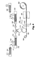
- the core layer and at least one of the first adhesive layer or the second adhesive layer are typically manufactured using an extrusion method, and the layers may be co-extruded.
- the thus manufactured tape Prior to use, the thus manufactured tape is generally exposed to a radiation source to cross-link at least one of the core, the first adhesive layer, or the second adhesive layer.
- an assembly comprising: a substrate; a carpet overlying the substrate; and a tape according to the invention disposed between the carpet and the substrate and adhering the carpet to the substrate.
- the invention also includes multi-layer articles, such as for example, multilayer tapes or sheets, adhesive transfer tapes, single-sided tapes, double-sided tapes, double-sided tapes with differentiated adhesion, and substrates onto which the adhesive has been directly applied.
- multi-layer articles such as for example, multilayer tapes or sheets, adhesive transfer tapes, single-sided tapes, double-sided tapes, double-sided tapes with differentiated adhesion, and substrates onto which the adhesive has been directly applied.
- the tapes described herein may include a tab.
- the invention provides a cleanly removable tape that can be used as a joining and mounting tape such as, for example, a carpet tape.
- the tapes are provided in layered constructions with stretch release properties to enable removal from a substrate without leaving significant residue on the surface of the substrate.
- the tapes comprise a core layer and at least a first adhesive layer adhered to at least a portion of the core layer.
- the tapes may be single sided tapes or double sided tapes. Single sided tapes are tapes having adhesive properties on one side only. Double sided tapes are tapes having adhesive properties on both sides.
- the first adhesive layer is provided as a skin adhesive on at least a portion of a first major surface of the core layer while the other major surface of the core layer may be provided with its own adhesive properties.
- a second adhesive layer may be provided to a portion of the core layer as another skin adhesive which may be the same adhesive as the first adhesive layer, or it may be a different than the first adhesive layer.
- the tapes of the invention may be dual sided tapes in that they are adhesively tacky on both sides of the core layer to permit the simultaneous adhesion of the tape to two different surfaces such as an article (e.g., a carpet backing) and a substrate (e.g., a floor).
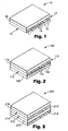
- the tape includes a core layer 14 in the form of a sheet having a first major surface 12 and a second major surface 13 opposite the first major surface 12.
- the major surfaces of the core layer 14 are typically smooth, but one or both of the major surfaces of the tape 10 may be provided with a texture or surface structures thereon.
- the core layer 14 comprises a plurality of viscoelastic and/or elastic microfibers 16 oriented in the manufacturing machine direction of the tape. The microfibers 16 provide the core layer 14 and the tape 10 with stretch releasable qualities when the tape 10 is adhered to a surface.
- a first adhesive layer 18 is adhered to at least a portion of the first major surface 12 of the core layer 14.
- the first adhesive layer 18 comprises a pressure sensitive adhesive (normally as a skin adhesive), but other types of adhesives may also be used.
- Additional microfibers may be included in the formulation of the first adhesive layer 18 as desired to further enhance the stretch release qualities of the tape by reinforcing the tape, especially when the tape is thin, i.e., less than about 0.25 mm (10 mils) or when the adhesive layer has high adhesion to a surface to which it is applied.
- the core layer 14 may be provided with adhesive properties so that the second major surface 13 of the core layer 14 has adhesive tack suited for the intended use of the tape product.
- the tackiness of the second major surface 13 is typically different than the tackiness of the first adhesive layer 18.
- the tackiness of the first adhesive layer 18 is generally formulated to provide a strong adhesive bond to a floor or other substrate while the tackiness of the core layer 14 along its second major surface 13 is formulated to provide a sufficiently strong bond to the material used for the backing of the carpet, and the bond between the carpet and the second major surface 13 is normally somewhat weaker than the adhesive bond between the first adhesive layer 18 and the floor or other substrate.
- the tape 10 may also include a tab (not shown) positioned thereon so that the tape 10 may be removed from a substrate by pulling the tab and the tape in the direction of the oriented microfibers 16, i.e., in the machine direction.
- the tape is moved by pulling on the tape or the tab in a direction substantially parallel to the two surfaces.
- the carpet or other adhered material is first removed from the tape by pulling the carpet or other material from the second major surface 13 of the tape 10.
- the tape 10 will remain adhered to the floor along the first major surface 12 via first adhesive layer 18, and removal of the tape 10 from the floor is accomplished by then stretching the tape in the machine direction at an angle from about 20° to about 45°, relative to the surface of the floor.
- the layers of the tape 10 may separate from one another leaving portions of the tape 10 that can be removed from the material and the substrate by the stretch-release mechanism.
- a force is applied to the tape in a direction substantially parallel to the surface of the floor or other substrate.
- the removal force may be applied by gripping the aforementioned removal tab or an end of the tape and pulling the tape in the aforementioned direction.
- the backing or core layer will deform.
- the tape comprises viscoelastic microfibers
- the tape will initially deform and then yield as the microfibers elongate and orient, thereby undergoing strain hardening.
- orientation induced by stretching further detackifies the adhesive layer. Stretching will thin the tape significantly at the location where the adhesive pulls away from the substrate. Thinning of the tape dramatically reduces the force required to remove the tape from the substrate.
- the substrate can be a fiber reinforced composite laminate or panel, and pulling the tape from the substrate at the foregoing angle significantly reduces the possibility that the panel surface will delaminate as a result of the tape removal process. Following the removal of the tape, the surface will be substantially clean with little or no visible adhesive residue remaining thereon.
- the tape 100 comprises core layer 114 having a first major surface 112 and a second major surface 113 and includes a plurality of microfibers 116 in the core layer 114.
- a first adhesive layer 118 is adhered to the first major surface 112 of the core layer 114 and a second adhesive layer 120 adhered to the second major surface 113 of the core layer 114.
- the core layer 114 need not be formulated as an adhesive.
- Both the first adhesive layer 118 and the second adhesive layer 120 are normally provided as pressure sensitive skin adhesives, and each of these adhesives may be provided as the same as the other, or the skin adhesives may be formulated differently from one another.
- the adhesive layers 118 and 120 are adhered to at least a portion of the major surfaces 112 and 113 of the core layer 114, and the adhesives may contain microfibers and comprise any of a variety of adhesive materials as are further described herein.
- the tape 200 comprises a first adhesive layer 214, a core layer 215, a second adhesive layer 218, and a release liner 219.
- the core layer 215 is positioned between first adhesive layer 214 and first side 212 of second adhesive layer 218.
- the release liner 219 is adjacent to and overlays the second side 213 of second adhesive layer 218.
- both the first adhesive layer 214 and the second adhesive layer 218 are formulated as pressure sensitive adhesives.
- One or both of the first adhesive layer 214 and the second adhesive layer 218 may contain antimony-free and polybrominated biphenyls-free fire retardant.
- the fire retardant comprises an intumescent fire retardant, a brominated phosphate fire retardant, or a combination of such fire retardants.
- the second adhesive layer 218 and the first adhesive layer 214 may comprise any of a variety of materials as are further described herein. The materials in this embodiment may be selected so that the tape 200 prepared therefrom is cleanly removable but not necessarily stretch-releasable as defined above. Although not shown, another release liner similar to the release liner 219 may be associated with the first adhesive layer 214.
- Suitable materials for the core layer 215 include any of a variety of films such as the polymeric films described herein.
- the core layer 215 may comprise woven and nonwoven materials, cloth, scrim, metallic foil, and the like.
- the core layer 215 may be or may not be elastic or viscoelastic. Normally, the core layer contains a fire retardant or is inherently fire retardant.
- the thickness of the core layer 215 is typically from about 0.0125 mm (0.0005 inch) to about 0.625 mm (0.025 inch), more often from about 0.0125 mm (0.0005 inch) to about 0.125 mm (0.005 inches) and most often from about 0.0125 mm(0.0005 inch) to about 0.051 mm (0.002 inches).
- the fire retardant, cleanly removable carpet tape described above can be prepared by any well known tape processing method such as by coating, such as, hot melt coating, solvent coating; lamination, hot melt extrusion and the like.
- the materials used in the core layer 215 and the skin adhesives 214 and 218 are selected to be compatible with one another and to provide a cleanly removable tape according to the invention. If a microfiber forming resin is included in one of the layers of the tape 200, the microfiber - containing layer is processed in a manner that generates the microfibers in situ. If the microfibers are present in the tape 200, the tape may be made cleanly removable using a stretch release mechanism, as described herein. However, it will be appreciated that the tape 200 may be cleanly removable without including microfibers in any of the layers of the tape. Moreover, the tape 200 may be cleanly removable without necessarily being stretch releasable.
- the skin adhesive layers used in the invention can be applied to the surface of the core layer in a continuous or discontinuous manner.
- One or more adhesives can be used in a single skin adhesive layer.
- a first adhesive may be pattern coated on the surface of the core layer and a second adhesive is thereafter coated onto the portions of the surface with no first adhesive.
- a second adhesive could be pattern coated onto a continuous coating of the first adhesive.
- the adhesive is a pressure sensitive adhesive.
- the adhesive is a hot melt pressure sensitive adhesive.
- a release liner may optionally be applied over the adhesive to protect it prior to its application to a substrate or the like. It will be appreciated that other layers and/or structures may be applied or affixed to at least a portion of one of the major surfaces of the core layer.
- any of a variety of materials may be used in the formulation of a core layer for the tapes of the invention.
- polymeric resins including adhesives as well as blends thereof, may be used.
- Thermoplastic polymers and adhesives suitable for use as a core layer include those that are compatible with, but immiscible with the fibrous reinforcing material. It may be desirable to blend two or more polymers having chemically different compositions.
- the physical properties of the resulting core layer can be optimized by varying the types of components used in creating the tape and by varying their relative concentrations. A particular resin is generally chosen or selected based upon the desired properties of the final stretch releasable tape.
- the core layer typically contains one or more fire retardants, as described herein, and may be treated with adhesion promoters, binders, antistatic materials, and the like to impart additional properties thereto.
- General criteria in the design of an acceptable general purpose stretch release, cleanly removable tape include: (1) break strength greater than the adhesion to the substrate such that the tape does not break during removal; (2) a Shore A hardness less than about 60, preferably, less than about 50, and more preferably less than about 45; (3) the skin adhesive preferably does not delaminate from the core layer; (4) the tape should stretch release in a cleanly removable manner from between a pair of substrates; (5) when the stretch release tape comprises viscoelastic microfibers, the tensile break strength should be at least about 150% of the yield strength of the tape with an elongation greater than about 200% and less than about 50% recovery after being elongated 100%, and when the stretch release tape comprises elastic fibers, the tape can have an elongation greater than about 200% and have greater than about 50% recovery after being elongated 100%; and (6) 90 degree peel adhesion to stainless steel or glass should generally be greater than about 0.176 kN/m (1 lbs/in), typically greater than about 0.352
- the criteria includes: (1) a split strength greater than the adhesion to the substrate such that the tape does not break during removal; (2) a Shore A hardness less than about 60, preferably, less than about 50, and more preferably less than about 45; (3) the skin adhesive preferably does not delaminate from the core layer; (4) the tape should be cleanly removable and should stretch release from a floor; (5) when the stretch release tape comprises viscoelastic microfibers, the tensile break strength should be at least about 150% of the yield strength of the tape with an elongation greater than about 200% and less than about 50 % recovery after being elongated 100%, and when the stretch release tape comprises elastic fibers, the tape can have an elongation greater than about 200% and have greater than about 50 % recovery after being elongated 100%; (6) 90 degree peel adhesion to stainless steel or glass should generally be greater than about 0.352 kN/m (2 lbs/in), typically greater than about 0.704
- Criteria for a fire retardant, cleanly removable carpet tape for aerospace applications includes: (1) satisfying the requirements of Boeing Material Specification BMS 5-133C, revised 29-Sep-1993; and (2) free from antimony based fire retardant and/or polybrominated biphenyls fire retardants or other environmentally unacceptable fire retardants.
- the fire retardant, cleanly removable carpet tape is additionally stretch releasable, the tape will meet all the requirements of BMS 5-133C except tensile strength.
- One group of polymers useful in the manufacture of the core layer includes acrylate and methacrylate polymers and copolymers and combinations thereof.
- Such polymers can be formed by polymerizing one or more monomeric acrylic or methacrylic esters of non-tertiary alkyl alcohols, with the alkyl groups having from 1 to 20 carbon atoms (e.g., from 3 to 18 carbon atoms).
- Suitable acrylate monomers include methyl acrylate, ethyl acrylate, n-butyl acrylate, lauryl acrylate, 2-ethylhexyl acrylate, cyclohexyl acrylate, iso-octyl acrylate, octadecyl acrylate, nonyl acrylate, decyl acrylate, and dodecyl acrylate.
- the corresponding methacrylates are useful as well. Also useful are aromatic acrylates and methacrylates, e.g., benzyl acrylate.
- one or more monoethylenically unsaturated co-monomers may be polymerized with the acrylate or methacrylate monomers.
- the amount of co-monomer may be based upon the desired properties of the polymer.
- One group of useful co-monomers includes those having a homopolymer glass transition temperature greater than the glass transition temperature of the acrylate homopolymer.
- suitable co-monomers falling within this group include acrylic acid, acrylamide, methacrylamide, substituted acrylamides such as N,N-dimethyl acrylamide, itaconic acid, methacrylic acid, acrylonitrile, methacrylonitrile, vinyl acetate, N-vinyl pyrrolidone, isobornyl acrylate, cyano ethyl acrylate, N-vinylcaprolactam, maleic anhydride, hydroxyalkylacrylates, N,N-dimethyl aminoethyl (meth)acrylate, N,N-diethylacrylamide, beta-carboxyethyl acrylate, vinyl esters of neodecanoic, neononanoic, neopentanoic, 2-ethylhexanoic, or propionic acids, vinylidene chloride, styrene, vinyl toluene, and alkyl vinyl ethers.
- Another group of monoethylenically unsaturated co-monomers which may be polymerized with the acrylate or methacrylate monomers includes those having a homopolymer glass transition temperature less than the glass transition temperature of the acrylate homopolymer.
- polymers useful for the core layer include polymers that are immiscible in, but are compatible with acrylic polymers.
- examples include semicrystalline polymer resins such as polyolefins and polyolefin copolymers (e.g., based upon monomers having between 2 and 8 carbon atoms such as low density polyethylene, linear low density polyethylene, ultra low density polyethylene, metallocene polyethylene copolymer, terpolymer, and tetrapolymer; atactic polypropylene, amorphous polypropylene and isotactic polypropylene blend, ethylene-propylene copolymers, etc.), polyesters and co-polyesters, polyamides and co-polyamides, fluorinated homopolymers and copolymers, polyalkylene oxides (e.g., polyethylene oxide and polypropylene oxide), polyvinyl alcohol, ionomers (e.g., ethylene-methacrylic acid copolymers neutralized with base), and cellulose
- acrylate-immiscible polymers include amorphous polymers having a solubility parameter (as measured according to the Fedors' technique) less than 8 or greater than 11 such as polyacrylonitrile, polyvinyl chloride, thermoplastic polyurethanes, aromatic epoxies, polycarbonate, amorphous polyesters, amorphous polyamides, acrylonitrile-butadiene-styrene (ABS) copolymers, polyphenylene oxide alloys, ionomers (e.g., ethylene-methacrylic acid copolymers neutralized with salt), fluorinated elastomers, and polydimethyl siloxane and combinations thereof
- thermoplastic elastomers containing ultraviolet radiation-activated groups examples include polybutadiene, polyisoprene, polychloroprene, random and block copolymers of styrene and dienes (e.g., SBR), and ethylene-propylene-diene monomer rubber and combinations thereof.
- polymers useful for the core layer include pressure sensitive and hot melt adhesives prepared from non-photopolymerizable monomers.
- Such polymers can be adhesive polymers (i.e., polymers that are inherently adhesive), or polymers that are not inherently adhesive, but are capable of forming pressure sensitive adhesive compositions when compounded with tackifiers.
- poly-alpha-olefins e.g., polyoctene, polyhexene, and atactic polypropylene
- tackified block copolymer-based adhesives natural and synthetic rubbers
- silicones ethylene-vinyl acetates
- polyurethanes e.g., polyurethanes
- epoxy-containing structural blends e.g., epoxy-acrylate and epoxy-polyester blends
- the core layer includes a plurality of elastic, viscoelastic, or combination of elastic and viscoelastic microfibers that reinforce the core layer while also providing the tape with stretch release properties.
- the elastic, viscoelastic, or combination of elastic and viscoelastic microfibers may also be included in both the core layer and skin adhesive layers.
- the microfibers are generated in situ from polymer resins during the manufacture of the core layer. Suitable microfibers include those formulated according to the teachings of pending United States Patent Application Serial No. 09/764,478, incorporated in its entirety herein by reference thereto.
- the reinforcing microfibers are viscoelastic and comprise semi-crystalline polymers (e.g., having both amorphous and crystalline domains).
- semi-crystalline polymers include polycaprolactone (PCL), polybutene (PB), copolymers derived from ethylene and at least one other alpha-olefin monomer (e.g. poly(ethylene-co-1-alkene) and poly(ethylene-co-1-alkene-co-1-alkene)), ultra low density polyethylene such as is commercially available under the trade designation ATTANE 4202 from Dow Chemical Co.
- metallocene copolymers such as the commercially available ENGAGE series available from Dupont-Dow Elastomers, or the metallocene polyolefins such as those known under the trade designation EXACT 3024, 3040 and 3139 (available from ExxonMobil Chemical Company), linear low density polyethylene (e.g.
- LL-3003 having a density between 0.915 and 0.94 grams/cubic centimeter, such as those available from ExxonMobil Chemical Company under the designations LL-3003, ECD-125, 377D60, 369G09, 363C32, 361C33, 357C32, 350D65, 350D64, 350D60, LL-3013, and LL-3001, and the those known under the trade designation DOWLEX available from Dow Chemical Co.
- the reinforcing microfibers are elastic.
- suitable reinforcing elastic microfibers include thermoplastic elastomers such as for example those comprising polyurethane, synthetic block copolymers, and combinations of the foregoing materials.
- the viscoelastic reinforcing microfiber materials will generally have a measurable yield strength. In certain embodiments, the yield strength of the reinforcing material is less than about 30 MPa.
- the tensile break strength of the viscoelastic reinforcing microfiber material is typically at least about 150% of its yield strength. In specific embodiments, the tensile break strength (measured according to ASTM D 882-97 at a crosshead speed of 12 inches/minute (30 centimeters/minute)) of the reinforcing microfiber material is higher than the tensile break strength of the skin adhesive and/or the core layer.
- Elastic reinforcing microfiber material should have greater than about 50% recovery after being elongated 100%.
- the reinforcing microfiber material should have a melting point above the use temperature of the skin adhesive composition and should have a melting point above the storage temperature of the adhesive composition or any tape made with the adhesive composition.
- the reinforcing microfiber material exists as substantially continuous fibers in the core and/or in adhesive layer.
- the microfibers are unbroken for at least about 0.5 centimeters in the machine direction of the adhesive or the core layer, preferably at least about 2 centimeters.
- the substantially continuous microfibers are continuous for at least about 5 centimeters and desirably are at least about 8 centimeters.
- the substantially continuous microfibers generally have a maximum diameter of about 0.05 to about 5 micrometers, typically from about 0.1 to about 1 micrometer.
- the aspect ratio i.e.
- the ratio of the length to the diameter) of the substantially continuous microfibers is greater than about 1000.
- the polymeric material of the core layer will comprise from about 80 to about 50 weight % of the tape while the fibrous reinforcing material will comprise from about 20 to about 50 weight % of the tape.
- the tape may have a lower split strength or a weaker bond between the core layer and the skin layer(s). This provides another method of removal by splitting the tape, and stretch releasing each portion individually. This removal method can be advantageous when tapes are used between two large surfaces.
- a suitable stretch release chemistry useful in the present invention comprises viscoelastic microfibers of certain homopolymers, copolymers, terpolymers, and tetrapolymers of polyalkylene resins including copolymers of polyoctene-ethylene and/or polyhexene-ethylene and the like.
- the microfibers will form in situ during the manufacturing process to provide a tape and/or adhesive material that will stretch, strain-harden and release during removal from a substrate without breakage.
- C 3 - C 10 copolymers with ethylene are suitable for use in the invention.
- polyoctene-ethylene and/or polyhexene-ethylene copolymers are compatible, but immiscible with many acrylic and rubber/resin based block copolymer adhesives and can be blended in a twin screw extruder, as described herein, to generate the microfibers in situ.
- the tapes of the invention may be provided with fire retardant properties.
- Fire retardants suitable for inclusion in the tapes of the present invention include intumescent fire retardants and/or non-intumescent, antimony free fire retardants which can be present in any layer of the tape, but are generally present in the core layer and the skin adhesive layer(s) of the tape at a concentration of between about 20 wt.% and about 60 wt.% based on the total weight of the tape. If the fire retardant is present in the skin adhesive layer, it is normally present in an amount less than about 50 wt.% of the weight of the skin adhesive layer, more typically less than about 40 wt. % and most often less than 30 wt. %.
- suitable fire retardants for use in the tapes described herein include those commercially available from Clariant Corporation of Charlotte, NC, under the designation EXOLIT, including those designated IFR 23, AP 422, AP 423, AP 452(TP), AP 462, AP 740(TP), AP 750, AP 751(TP), and AP 752(TP), all of which are non-halogenated fire retardants comprising ammonium polyphosphate and/or synergists. Synergists are other fire retardant materials that, when combined with another fire retardant, provide enhanced fire retardant properties greater than the additive properties of the two fire retardant materials.
- EXOLIT OP grade materials such as, OP 550, OP 910, OP 920(TP), OP 921(TP), OP 1100(TP), EXOLIT 5060, EXOLIT 5073, EXOLIT 5085(VP), and EXOLIT 5087, also from Clariant Corporation, based on organophosphorous compounds are also useful as well as EXOLIT RP grades of red phosphorus materials, such as, RP 622, RP 650, RP 652, RP 654, RP 658, RP 6,59(TP), RP 683(TP), RP 689(TP), RP 692, RP 693, and RP 694.
- non-halogenated fire retardants include FIREBRAKE ZB and BORGARD ZB which are zinc borate and zinc borate hydrate respectively, ammonium borate / diborate / tetraborate tetrahydrate, ammonium pentaborate x 8H 2 O, FYREX which is a mixture of diammonium and monoammonium phosphate, available from Akzo Nobel, Gallipolis Ferry, West Virginia; triphenyl phosphate, di-melamine phosphate, potassium bicarbonate, potassium aluminum sulfate, MELAPUR 25 and MELAPUR p-46 which are both melamine cyanurates; MELAPUR 200 which is melamine polyphosphate, all three of which are available from DSM Melamine Americas, Inc.
- AMGARD NH which is melamine phosphate
- ANTIBLAZE NP which is alkyl amine phosphate
- ANTIBLAZE NK which is alkyl amine phosphate salt
- ANTIBLAZE MC which is ammonium polyphosphate
- AMGARD NP which is ethylene diamine phosphate, all of which are available from Albright & Wilson Americas Inc., Richmond, VA
- REOGARD 1000 which is a proprietary intumescent fire retardant which is available from Great Lakes Chemical Corp., West Lafayette, IN
- aluminum trihydrate (ATH), magnesium oxide, and magnesium hydroxide aluminum trihydrate
- Useful halogenated phosphate fire retardants that may be used include TCEP (tris(2-chloroethyl)phosphate) and TCPP (tris(2-chloroisopropyl)phosphate) both of which are available from Clariant Corporation, and FR 370 (tris(tribromoneopentyl) phosphate) available from Dead Sea Bromine Group, Beer Shiva, Israel. Further examples of useful fire retardants that are non-intumescent are described in U.S. Pat. No. 6,022,914 (Nowak et al.) and intumescent fire retardants that are described in U.S. Pat. No. 5,851,663 (Parsons et al.) both of which are incorporated herein by reference.
- Blends of one or more fire retardants may also be used in the tapes of the invention. Suitable blends include blends of EXOLIT AP 750 and FR370 and EXOLIT IFR 23 and FR 370 in a weight ratio ranging from about 5:95 to about 95:5, and blends of mono-ammonium phosphate, ammonium sulfate, and magnesium aluminum silicate available as FORAY from Ansul Incorporated. Blends of one or more fire retardants and a synergist may also be used in the tapes of the invention.
- Suitable synergists include talc, magnesium compounds, zinc compounds such as zinc borate, Fe 2 O 3 , MoO 3 , special zeolite, boroxo siloxane elastomer, which are discussed in article "Influence of Modified Rheology on the Efficiency of Intumescent Flame Retardant Systems", P. Anna et al., Polymer Degradation and Stability , Vol. 74 (3), 2001, pp. 423 to 426.
- a synergist for both brominated and phosphorus fire retardants is CIBA FLAMESTAB NOR 116 fire retardant material available from Ciba, Tarrytown, NY.
- FR 370 which is tris(tribromoneopentyl) phosphate, is a very effective fire retardant for the preparation of fire retardant, cleanly removable carpet tapes.
- FR 370 has not been identified by environmental groups, such as the European Parliament, as a troublesome substance and has been determined to be an effective replacement for antimony trioxide and/or polybrominated biphenyls.
- the core layer may also include a number of other additives.
- suitable additives include tackifiers (e.g., rosin esters, terpenes, phenols, and aliphatic, aromatic, or mixtures of aliphatic and aromatic synthetic hydrocarbon resins), plasticizers, pigments, dyes, non-expandable polymeric or glass microspheres, expandable microspheres, reinforcing agents, hydrophobic or hydrophilic silica, calcium carbonate, toughening agents, antioxidants, finely ground polymeric particles such as polyester, nylon, or polypropylene, stabilizers, conductive particulates (thermally and/or electrically conductive), antistatic agents, fillers, blowing agents, adhesion promoters, such as silanes, nanoparticles, such as nanoclay, non-polymeric fibers, and combinations thereof.
- tackifiers e.g., rosin esters, terpenes, phenols, and aliphatic, aromatic, or mixture
- the foregoing additional agents and components are generally added in amounts sufficient to obtain a tape having the desired end properties, but not so as to interfere with microfiber formation described herein.
- the total volume percent of all additives is less than about 70 volume percent, more preferably, less than about 60 volume percent, and most preferably, less than about 50 volume percent.
- the particle size of the additive(s) is small (i.e., no greater than about 100 micrometers, typically no greater than about 10 micrometers, often no greater than about 5 micrometers, and most often no greater than about 1 micrometer) in order not to interfere with microfiber formation.
- polymer resin or adhesive polymer is fed into a first extruder 310 (typically a single screw extruder) to soften, grind, or melt the resin into a form suitable for extrusion.
- the resulting polymer resin will form the core layer.
- the polymer resin may be added to the extruder 310 in any convenient form, such as pellets, billets, packages, strands, pouches and ropes.
- the polymer resin is fed to a second extruder 312 (e.g., typically a twin screw extruder).
- the polymer resin may be fed directly from the extruder 310 into second extruder 312 through port 311.
- additives such as fire retardants and microfiber forming resin
- the order of component addition and mixing conditions e.g., screw speed, screw length, and temperature
- mixing is carried out at a temperature of at least about 10°C above the melting point temperature of the microfiber forming resin and less than about the degradation temperature of the material to which the microfiber forming resin is added and/or the microfiber forming resin.
- mixing is carried out at a temperature between about 140°C to about 170°C. However, higher temperatures may be used. It will be appreciated that if the polymer resin is provided in a form suitable for extrusion, the first extrusion step may be omitted, and the resin is added directly to extruder 312.
- the appropriate resins for forming microfibers may also be added to the extruder 312 at downstream entrance 313 or another port (not shown). Preferably the microfiber forming resins are added separately from the other additives.
- the melt-mixing step prepares a composition in which the microfiber forming material and other additives are distributed throughout a molten polymer resin. Typically, the melt-mixing operation uses at least one kneading block downstream from entrance 313 to obtain adequate mixing of the various components.
- the temperature, pressure, shear rate, and mixing time employed during melt-mixing are selected to prepare a void-free extrudable composition suitable for use as a tape and/or as a core layer that is part of a multilayer tape .
- zone temperatures, pressures, shear rates, and mixing times are also selected based upon the particular chemical compositions being processed, and the selection of these conditions is within the skill of those practicing in the field.
- the preferred order of addition is polymer resin/adhesive, fire retardant(s) and other additives, if any, microfiber forming resin, and tackifier, if any.
- the reinforcing microfibers are desirably formed with material having a melt viscosity (as determined with a capillary viscometer) similar to the melt viscosity of the polymer core material at the die 314 temperature of the above method.
- the reinforcing microfiber material is selected to be immiscible in, but compatible with the polymer material.
- the physical properties of the stretch releasable tape are affected by how well the microfibers are formed, and the formation of the microfibers are affected by the processing conditions and compatibility with the core layer polymer resin. It is important that the melt viscosities of the microfiber forming resin and the core polymer are closely matched and processing conditions are right to generate continuous microfibers.
- the ratio of the melt viscosities of the microfiber forming resin and the core polymer is from about 1:30 to about 30:1 and preferably, from about 1:20 to 20:1.
- the microfiber material is typically melted, mixed and dispersed in the core material as substantially spherical resin droplets. These droplets generally have an average diameter less than about 20 micrometers and sometimes less than about 10 micrometers.
- the resulting extrudable composition is metered into an extrusion die 314 (e.g., a contact or drop die) through transfer tubing 318 using a gear pump 316.
- the temperature within die 314 is maintained at substantially the same temperature as the temperature within transfer tubing 318. While the temperature within tubing 318 will be elevated, it is generally maintained low enough to avoid degradation of the polymer or the components.
- the pressure within the die 314 will generally decreases as the polymer core composition approaches the exit port 315 of the die 314.
- the flow rate of the extrudable polymer composition through the extruder 312 and the die 314 is maintained to adequately process the core layer, as known by those skilled in the art.
- the manufacturing process temperatures are typically chosen so that the temperatureof the highest or last zone is between at least about 10°C above the melting point (low limit) of elastic, viscoelastic, or combination of elastic and viscoelastic polymer resins and less than about the degradation temperature of the components.
- the temperature of the die 314 is generally no greater than about 60°C over the melting point of the microfiber forming polymer so that the microfiber can effectively consolidate by crystallizing upon cooling into relatively long, substantially continuous microfibers.
- the smoothness of one or both of the major surfaces of the tape core layer, and/or adhesive layers can be increased by using a nip roll to press the core against a smooth chill roll 317 after the core exits die 314, or by using smooth liners on each of the major surfaces of the multilayered tape and passing the composite article through a nip. It is also possible to emboss a pattern on one or both major surfaces of the multilayered tape by using a patterned or microstructured liner such as those described in United States Letters Patent No. 6,197,397 issued to Sher et al. on March 6, 2001 or by contacting the tape with a patterned roll, for example, a patterned chill roll, after it exits the die 314.
- the core layer may be combined with one or more skin adhesive layers.
- Figure 4 shows a co-extrusion process for use in the present invention.
- a layer of skin adhesive material is introduced to the system by adding a resin or adhesive polymer to the extruder 330 (e.g., a single screw extruder).
- the resin or adhesive material is softened, mixed, or melted and then fed to a second extruder 332 (e.g., a single or twin screw extruder).
- Additives such as the microfiber resins, tackifiers, fire retardants, etc. may be also be included in the skin adhesive by adding the additional components to the extruder 332 at downstream port 329 where the additives are mixed with the adhesive material.
- the microfiber forming resins are added separately from the other additives.
- the melt-mixing step prepares a composition in which the microfiber forming material and other additives are distributed throughout a molten adhesive polymer resin.
- the melt-mixing operation uses at least one kneading block downstream from entrance 329 to obtain adequate mixing of the various components.
- the temperature, pressure, shear rate, and mixing time employed during melt-mixing are selected to prepare a void-free extrudable composition suitable for use as an adhesive skin layer.
- the additives, the order of their addition, zone temperatures, pressures, shear rates, and mixing times are also selected based upon the adhesive formulation, and the selection of these conditions is within the skill of those practicing in the field.
- the preferred order of addition is polymer resin/adhesive, fire retardant(s) and other additives, if any, microfiber forming resin, and tackifier, if any.
- the number of additives, the order of their addition, and their point of addition are selected based on the adhesive formulation to provide desired adhesive properties suitable for the intended application of the final tape product
- an extrudable adhesive composition is metered from the extruder 332 to the appropriate chambers of die 314 through transfer tubing 334 using gear pump 336.
- the adhesive composition is co-extruded with the core layer through an exit port 315 on the die 314 so that the adhesive composition is applied directly to one of the major surfaces of the core layer. It will be appreciated that an adhesive composition may be applied to the core layer on either or both of the major surfaces.
- Co-extrusion methods for coating an article with adhesive are known to those in the art and are not further explained here.
- the resulting tape is a three-layer (ABA or ABC) construction of the kind illustrated in Figure 2 and described herein.
- ABA or ABC additional extruders and related equipment may be added to the system of Figure 3 in a known manner to permit both first and second skin adhesives to be applied to the first and second major surfaces of the core layer.
- one or both of the adhesive compositions may be applied to the core layer by lamination, by coating, or by spraying the adhesive onto the core.
- the first and second adhesives may be continuous or discontinuous adhesive layers applied to the major surfaces of the core layer, and the skin adhesives may be the same or different adhesive compositions on each of the major surfaces, and either of the adhesive layers may be provided with a three dimensional surface structure.
- the skin adhesive has a peel adhesion strength that is less than the tear or tensile break strength of the core layer or composite tape construction.
- Suitable skin adhesives for use in the articles of the present invention include any adhesive that provides acceptable adhesion to a variety of polar and non - polar substrates while also being compatible with the composition used in the core layer in the manner described herein.
- the thickness of the skin adhesive has an effect on peel adhesion. Consequently, the thickness of the skin adhesive should be at least about 0.012 mm (0.5 mil), and typically, at least about 0.051 mm (2 mils), and generally, less than 0.25 mm (10 mils).
- the skin adhesive not adhere too strongly to a substrate, i.e., have a 90 degree peel adhesion less than about 5.25 kN/m (30 lbs/in), preferably less than about 3.50 kN/m (20 lbs/in) and more preferably less than about 1.75 kN/m (10 lbs/in).
- Pressure sensitive adhesives are generally acceptable and may be desired.
- Suitable pressure sensitive adhesives include any of a variety of adhesives such as those based on acrylic adhesives (including copolymers, terpolymers, and tetrapolymers of (meth)acrylate(s) and comonomers such as (meth)acrylic acid, vinyl acetate, and dimethyl acrylamide), polyurethanes, thermoplastic elastomers such as styrene-isoprene-styrene, styrenebutadiene-styrene, and combinations thereof, and other block copolymers, polyolefins such as poly-alpha-olefins and amorphous polyolefins, silicones, rubber based adhesives (including natural rubber, polyisoprene, polyisobutylene, butyl rubber etc.) and combinations and blends of the foregoing adhesives.
- acrylic adhesives including copolymers, terpolymers, and tetrapolymers of (meth)acryl
- the adhesive component may contain tackifiers, plasticizers, rheology modifiers, adhesion promoters such as silanes, fillers, non-polymeric fibers, crosslinking agents, ceramic microspheres, glass microspheres, expanded and unexpanded polymeric microspheres, conductive particulates (thermally and/or electrically conductive), antistatic agents, antioxidants, dyes, pigments, stabilizers, blowing agents, surfactants, nanoparticles such as nanoclays, microfiber forming resin, and other additives as well as active components such as an antimicrobial agent or the like.
- a group of pressure sensitive adhesives known to be useful in the present invention are, for example, the acrylate copolymers described in U.S. Pat. No.
- a release liner 320 may be applied to the skin adhesive layer or layers associated with either or both of the major surfaces of the core layer.
- a release liner 320 can be dispensed from a feed roll 322 and applied to a surface of the skin adhesive.
- Suitable materials for liner 320 include silicone release liners, polyester films (e.g., polyethylene terephthalate films), and polyolefm films (e.g., polyethylene films).
- the liner and the adhesive may be laminated together between nip rollers 324.
- a second optional release liner 340 may be applied to the other major surface of the core layer.
- the liner 340 may be dispensed from a second feed roll 342 which feed the liner 340 to the nip roll 324.
- the liner is then applied to the adhesive layer as the core and associated adhesive pass between nip rolls 324.
- the pressure from the nip rolls 324 serves to laminate the release liners 320 and 340 to the multi-layer
- the second release liner 340 may be provided with a layer of an adhesive coated or applied to one surface of the release liner 340.
- the second adhesive layer may be applied to the second major surface of the core material.
- the second adhesive layer may be the same as or different from the aforementioned co-extruded adhesive.
- the adhesive layers will comprise pressure sensitive adhesives.
- the adhesive layers may or may not contain microfibers.
- Release liner 320 may also be provided with a layer of an adhesive coated or applied to one of its surfaces.
- the liner 340 can be dispensed from a feed roll (not shown) and applied to the surface of the chill roll 317 such that extrudate from die 314 is coated onto liner 340.
- the tape is optionally exposed to radiation from an electron beam source 326, for example, to crosslink the polymeric core and/or to crosslink the adhesive layer(s).
- an electron beam source 326 for example, to crosslink the polymeric core and/or to crosslink the adhesive layer(s).
- the radiation should be energetic enough to penetrate the thickness of the core to initiate and complete the crosslinking reaction.
- the extruded core layer may be of a thickness that irradiation by e-beam exposure is needed on both sides of the core for adequate crosslinking.
- the resulting multilayer tape laminate is rolled up onto a take-up roll 328.
- the tape can be wound into a roll and subsequently irradiated.
- the release liners are typically coated with release agents such as fluorochemicals or silicones.
- release agents such as fluorochemicals or silicones.
- U.S. Pat. No. 4,472,480 describes low surface energy perfluorochemical liners.
- Suitable release liners include papers, polyolefin films, or polyester films coated with silicone release materials. Examples of commercially available silicone coated release liners are POLYSLIK TM silicone release papers available from James River Co., H.P. Smith Division (Bedford Park, IL.) and silicone release papers supplied by DCP-Lohja (Dixon, IL.) now known as Loparex Inc. (Willowbrook, IL).
- a particular release liner is that known by the designation 1-60BKG-157, a super calendared Kraft paper with a water-based silicone release surface, available from Daubert Chemical Co.
- Other types of stable, contaminent free, release liners are also useful in the invention such as those described in U.S. Patent Application Serial No. 09/775,955 incorporated herein by reference.
- multi-layered constructions can be accomplished by equipping die 314 with an appropriate feed block, or by using a multi-vaned or multi-manifold die.
- multilayered tapes can also be prepared by laminating, coating, or spraying skin adhesive layers or other additional polymer layers to the core layer, or to any of the co-extruded polymer layers after the core exits die 314.
- the core layer can be extruded directly onto a backing layer or onto a release liner bearing a skin adhesive layer.
- Other techniques which can be used include pattern coating. It is preferred that tape 200 be prepared by the processes described in U. S. Patent No. 5,660,922, issued August 26, 1997.
- the tapes of the invention are useful in a variety of applications, and are especially useful as carpet tape in aerospace, electronic, automotive, and medical applications as well as in advertising and displays.
- the properties of the articles may be tailored to meet the demands of the desired applications.
- the tapes can also be used as attachment systems for or as a means for mounting a wide variety of articles such as signage, reclosable fasteners, body side molding, panels, hooks, clips, and the like. Additional applications include closure applications such as container closures, diaper closures, and surgical drape closures.
- This test method is based on the criteria and procedures for showing compliance with F.A.R. ⁇ 25.853 (July 1990) but differs from F.A.R. ⁇ 25.853 (July 1990) in that the specimens (samples) were conditioned at 50% ⁇ 10 % relative humidity for a minimum of 24 hours instead of the specified 50% ⁇ 5%.
- Samples were conditioned to 21.1° C. ⁇ 2.8° C. (70° ⁇ 5° F.) and at 50% ⁇ 10 % relative humidity for a minimum of 24 hours.
- Specimens were mounted into a U-shaped metal frame so that the two long edges and one narrow edge were held securely in a vertical orientation, unsupported by and unattached to a substrate.
- the exposed area of the specimen was at least 50.8 mm (two inches) wide and about 304.8 mm (12 inches) long.
- the samples were exposed to the flame from a Bunsen burner.
- the lower edge of the sample was about 19.1 mm (3/4 inch) above the top edge of the burner.
- the flame was applied to the center line of the lower edge of the sample for 12 seconds.
- the flame time, burn length, and flaming time of dripping, if any, was recorded.
- Burn length was the distance from the original edge of the sample that was exposed to the flame to the point which is the farthest evidence of damage to the test specimen due to flame impingement including area of partial or complete consumption, charring, or embrittlement, but not including areas sooted, stained, warped, or discolored, nor areas where material had shrunk or melted away from the heat.
- F.A.R. ⁇ 25.853 July 1990 subparagraphs (a)(1)(i) 60 second flame exposure require that the average burn length not exceed 152.4 mm (six inches), the average flame time after removal of the flame source not exceed 15 seconds, and drips not continue to flame for more than an average of 3 seconds after falling.
- F.A.R. ⁇ 25.853 subparagraphs (a)(1)(ii) 12 second flame exposure require the average burn length not exceed 203 mm (8 inches), the average flame time after removal of the flame source not exceed 15 seconds, and drips not continue to flame for more than an average of 5 seconds after falling.
- a 12.7 mm (one-half inch) wide by about 152 mm (6 inches) long sample was cut from the article to be tested and laminated to an about 165 mm (6.5 inches) long by about 28.6 mm (1.125 inches) wide by 0.051 mm (0.002 inches) thick aluminum foil by rolling down the article onto the aluminum foil, taking care not to trap air bubbles between the foil and the article.
- the foil/article laminate was then positioned on a clean, dry, 51 mm (two inches) wide by about 127 mm (5 inches) long, substrate panel of stainless steel or to a Boeing composite, as specified in the Examples below, so that the laminate was centered on the panel with a portion of the laminate extending off the panel to serve as a tab.
- the laminate was rolled down onto the panel using a 2 kg (4.5 lb) hard rubber roller, with two passes in each direction. Care was taken not to trap bubbles between the panel and the laminate.
- the sample thus prepared was allowed to dwell at room temperature (about 22°C) or at 70°C for about 72 hours. Then the sample was tested at room temperature (about 22°C) for 90 Degree Peel Adhesion according to the Pressure Sensitive Tape Council test method PSTC-5 "Quick Stick of Pressure Sensitive Tapes" at crosshead speed of 30 cm/minute (12 inches/minute) using an INSTRON tensile tester. That is, the peel value obtained from the first 25.4 mm (one inch) length of peel was ignored. The peel value of the next 89 mm (3.5 inches) or "peel area" was recorded. The values reported were the integrated peel adhesion values. Failure mode was also noted for 70°C aged samples.
- a 12.7 mm (one half inch) wide by about 152 mm (6 inches) long sample was cut from the article to be tested and laminated to an about 165 mm (6.5 inches) long by about 28.6 mm (1.125 inches) wide by 0.051 mm (0.002 inches) thick aluminum foil by rolling down the article onto the aluminum foil, taking care not to trap air bubbles between the foil and the article.
- the foil/article laminate was then positioned on a clean, dry, 51 mm (two inches) wide by about 127 mm (5 inches) long, back of a carpet panel, FELTEX CARPET Style 282131, available from Feltex Carpet Ltd, Auckland, NZ, so that the laminate was centered on the carpet back with a portion of the laminate extending off the carpet back to serve as a tab.
- the laminate was rolled down onto the carpet back using a 2 kg (4.5 lb) hard rubber roller, with two passes in each direction. Care was taken not to trap bubbles between the carpet back and the laminate.
- the sample thus prepared was allowed to dwell at room temperature (about 22°C) or at 70°C for about 72 hours.
- a 1.27 cm (one-half inch) wide by about 15.2 cm (6 inches) long sample was cut from the article to be tested and laminated to a sheet of anodized aluminum foil (about 16.5 cm (6.5 inches) long by 2.86 cm (1.125 inches) wide by 0.0127 cm (0.005 inches) thick) by rolling down the article onto the anodized side of the aluminum foil, taking care not to trap air bubbles between the foil and the article.
- the foil/article laminate was then cut in half to give two about 2.54 cm x about 7.62 cm (1 inch x 3 inches) test specimens.
- the liner was removed from a test specimen and then positioned on a clean, dry, 5.1 cm (two inches) wide by 12.7 cm (5 inches) long, stainless steel substrate panel so that the laminate was centered on one end of the panel so that 2.54 cm (1 inch) length was adhered (i.e. 3.13 sq. cm (0.5 sq. inch) bond area) and the 5.1 cm (2 inches) portion of the laminate extended off the panel to serve as a tab.
- the laminate was rolled down onto the panel using a 2 kg (4.5 lb) hard rubber roller, with two passes in each direction. Care was taken not to trap bubbles between the panel and the laminate.
- the 5.1 cm (2 inches) tab was then folded around a triangular clip and stapled so that a weight could be attached to the test specimen.
- the sample thus prepared was allowed to dwell at room temperatures and approximately 50 % relative humidity for approximately 72 hours.
- the test specimen was then placed in a Static Shear standard fixture having between zero and 2 degree angle back slant in a forced air oven set at 70°C (158°F).
- the test specimen was then given a 10 minute warm up period before attaching a 500 gram weight.
- the test was run until the test specimen failed or 10,000 minutes elapsed. Failure time and failure mode were recorded. Where the test specimen did not fail, the amount of slippage was measured and recorded.
- a silicone release liner was applied to the exposed surface of the article which already had a liner on one side.
- a 2.54 cm (one inch) wide by about 12.7 cm (5 inches) long sample was cut in the machine direction from the article to be tested to form the test specimen.
- One release liner was removed and a 2.54 cm (1 inch) length was measured and marked in the center of test specimen to provide the initial gap distance.
- a 2.54 cm (1 inch) wide by about 7.62 cm (3 inch) piece of masking tape was placed across the foam article by positioning the tape edge on both marks so that the 2.54 cm (1 inch) long section that was marked off did not have tape covering it.
- the other liner was then removed, and masking tape was wrapped completely around the article. Care was taken to keep the masking tape aligned with the marks on the article.
- the tape was used to prevent the sample from adhering to the INSTRON jaws and prevent the sample from breaking at the point where it was clamped by the jaws.
- the INSTRON was set up with the following conditions:
- the thickness of an about 5.1 cm (two inches) by 2.54 cm (one inch) article sample was measured and recorded. The sample was then laminated to a clean, dry glass panel taking care to avoid trapping air bubbles between the sample and the glass. Additional pieces of article sample were laminated to the first article until a total thickness of at least 0.34 cm (0.135 inches) was achieved. Using a Shore A Hardness Tester (Model CV Stand and Durometer Type A ASTM D2240 Gauge available from Shore Instrument Mfg. Co. Inc., Freeport, NY), the initial hardness of the article was measured three times and the maximum hardness values obtained were averaged.
- Shore A Hardness Tester Model CV Stand and Durometer Type A ASTM D2240 Gauge available from Shore Instrument Mfg. Co. Inc., Freeport, NY
- test strips were pulled by hand at a speed of about 30 cm/minute (about 12 inches/minute) in a direction away from the panels to initiate stretch release removal until the bond failed.
- the test strips were pulled at an angle that was approximately between 10 and 25 degrees above the plane of the panel. The panels were then visually examined for the presence of residue and the number of times the strip broke.
- Three pressure-sensitive adhesive compositions were prepared by mixing 2-ethylhexyl acrylate (2-EHA), acrylic acid (AA), 2,2-dimethoxy-2-phenylacetophenone (IRGACURE 651), and isooctyl thioglycolate (IOTG) in the amounts listed in Table 1 below.
- Each composition was formed into a "Packaged Pressure Sensitive Adhesive" by placing the composition into packages measuring approximately 100 mm by 50 mm by 5 mm thick as described in U.S. Pat. No.5,804,610 (Hamer et al).
- the packaging film was 0.0635 mm (0.0025 inches) thick VA-24 film (a heat sealable, ethylene vinyl acetate copolymer film having 6% vinyl acetate, available from CT Film of Dallas, TX).
- VA-24 film a heat sealable, ethylene vinyl acetate copolymer film having 6% vinyl acetate, available from CT Film of Dallas, TX.
- the packages were immersed in a water bath and at the same time exposed to ultraviolet radiation at an_intensity of 3.5 milliwatts per square centimeter and a total energy of 1627 millijoules per square centimeter as measured by NIST units to form a "Packaged Pressure Sensitive Adhesive (Pkg. PSA)".
- Table 1 Component Parts by Wt. of 2-EHA Parts by Wt. of AA Parts by Wt. of IOTG Parts by Wt. of 2,2-dimethoxy-2-phenylacetophenone Pkg.
- Packaged Pressure Sensitive Adhesive IV was a commercial hot melt adhesive available from H. B. Fuller Company under the designation HL2081.
- PSA I was fed to the second feed port of a 30 mm co-rotating twin screw extruder (Werner Pfleider) operating at a screw speed of 300 rpm through a first 51 mm single screw extruder (Bonnot).
- the pump and heated hose were set at 177°C (350°F).
- the temperature for the six zones in the twin screw extruder was set in Zone 1 at 163°C (325°F), and in Zones 2 through 6 at 121°C (350°F).
- the adhesive was delivered into a silicone coated paper box though a heated hose set at 121°C (350°F).
- the skin adhesive was identified as "Precompounded Adhesive A" as shown in Table 2 below.
- Adhesive B in Table 3 below was Pkg.
- a Pkg. PSA was fed at a rate of 12 lbs/hr (5.45 kg/hr) to Barrel Zone 1 of a 30 mm co-rotating twin screw extruder (Werner Pfleider) operating at a screw speed of 300 rpm through a first 51 mm single screw extruder (Bonnot).
- the pump and heated hose were set at 177°C (350°F).
- Zone 1 37.8°C (100°F)
- Zones 2 79.4°C (175°F)
- Zones 3 37.8°C (100°F)
- Zones 4 160°C (320°F)
- Zones 5 160°C (320°F)
- Zone 6 160°C (320°F).
- the flame retardant(s) was added to Barrel Zone 3 using a KTRON weight loss feeder, Model No.F-7, available from K Tron Corp, Pitman, NJ.
- the tackifying resin(s) was melted in a resin melting system, and was added into Barrel Zone 5.
- the resin melting tank temperature was set at 148.9°C (300°F), and the pump and heated hose were set at 162.8°C (325°F).
- the feed rate for both the fire retardant(s) and tackifying resin(s), if present, was adjusted based on the set 12 lbs/hour (5.45 kg/hr) flow rate of the Pkg. PSA to give the desired level of parts in the formulation as shown in Table 2.
- the adhesive was delivered into a silicone coated paper box though a heated hose set at160°C (320°F).
- the skin adhesives were identified as "Precompounded Adhesive C, D, E, F and G" as shown in Table 2 below.
- Table 2 Component Type Component Precormounded Skin Adhesives, Parts by Wt. A B C D E F G Adhesive Polymer Pkg.
- PSA I 100 Pkg.
- PSA II 100 100 100 100 Pkg.
- PSA III 100 Pkg.
- PSA IV 100 Tackifying Resin ECR 180 39 RE80HP 39 39 39 49 49 Fire Retardant EXOLIT IFR 23 75 75 50 FR 370 49 49
- a Pkg. PSA was fed at a rate of 2.27 kg/hr (5 lb/hr) to Barrel Zone 1 of a 30 mm co-rotating twin screw extruder (Werner Pfleider) operating at a screw speed of 300 rpm through a first 51 mm single screw extruder (Bonnot).
- the pump and heated hose were set at 177°C (350°F).
- Zone 1 37.8°C (100°F)
- Zone 2 37.8°C (100°F)
- Zone 3 37.8°C (100°F)
- Zone 4 160°C (320°F)
- Zone 5 160°C (320°F)
- Zone 6 160°C (320°F).
- the flame retardant(s) was added to Barrel Zone 3 using a KTRON weight loss feeder.
- the fiber forming resin was added to Barrel Zone 3 using a KTRON weight loss feeder.
- the feed rate for both the fire retardant(s), if present, and fiber forming resin was adjusted based on the set 2.27 kg/hr (5 lb/hr) flow rate of the Pkg. PSA to give the desired level of parts in the formulation as shown in Table 3.
- the core adhesives were identified as "Compounded Core Adhesive H, I, J, K, L, M, and N" as shown in Table 3 below.
- the Compounded Core Adhesive was not isolated but was fed to the middle layer of a three layer die as described below in Examples 1-11.
- Table 3 Component Type Component Compounded Core Adhesive, Parts by Wt. H I J K L M N Adhesive Polymer Pkg.
- PSA II 100 Pkg.
- PSA III 100 100 100 Pkg.
- PSA IV 100 Fiber Forming Resin EXACT 3040 54 54 54 54 54 54 54 65 87 Fire Retardant EXOLIT IFR 23 75 75 75 FR 370 49 49
- a Precompounded Skin Adhesive was fed to the each of the outer layers of the die from a second 51 mm single screw extruder (Bonnot) and coextruded with the core adhesive extrudate above.
- the Bonnot zone temperatures were all set at 149°C (300°F).
- the pump and heated hose were set at 163°C (325°F).
- the skin adhesive flow rate was adjusted to provide a target thickness of each outer layer of 0.076 mm (3 mils).
- the process conditions were adjusted to provide the tape thickness set forth in Table 4.
- the extruded sheet was cast onto a chill roll that was set at 7.2°C (45.5°F), cooled to about 25°C, and then transferred onto a 0.127 mm thick polyethylene release liner prepared according to Examples 10a and 10b of copending U.S. patent application serial no. 09/775955 "Adhesive Article and Method of Preparing.”
- the resulting article was wound into a roll for subsequent crosslinking.
- Examples 4 and 5 have both rubber based skin adhesive layers and a rubber based adhesive core layer and would not be expected to have good shear at 70°C.
- the tensile break strength of the tape can be increased by increasing the concentration of the microfibers and/or the thickness of the core layer to prevent breaking during the Stretch Release Test for the tapes of Examples 1, 6, 7 and 9.
- Examples 9, 10, and 11 could be improved by reducing the amount of tackifying resin used, by increasing the total amount of fire retardant, and by substituting a brominated fire retardant, such as FR 370, for a portion of IFR 23 fire retardant.
- a fire retardant, cleanly removable carpet tape as shown in Figure 3 was prepared as follows:
- the skin adhesive is identified as “Compounded Skin Adhesive O” and the core adhesive is identified as “Compounded Core Adhesive P”. Both the skin and core adhesives were not isolated, but were individually feed to a rotary die and coated onto a release liner.
- PSA II was fed at a rate of 2.27 kg/hr (5 lbs/hr) to Barrel Zone 1 of a 30 mm co-rotating twin screw extruder (Werner Pfleider) operating at a screw speed of 300 rpm through a first 51 mm single screw extruder (Bonnot).
- the pump and heated hose were set at 177°C (350°F).
- Zone 1 37.8°C (100°F)
- Zones 2 37.8°C (100°F)
- Zones 3 37.8°C (100°F)
- Zones 4 160°C (320°F)
- Zones 5 160°C (320°F)
- Zone 6 160°C (320°F).
- the fire retardants EXOLIT IFR 23 and FR 370, were added to Barrel Zone 3 using a KTRON weight loss feeder.
- the tackifying resin, RE 80 HP was melted in a HELICONE resin melting system, and added into Barrel Zone 5.
- the HELICONE tank temperature was set at 148.9°C (300°F), and the pump and heated hose were set at 162.8°C (325°F).
- the feed rates for both the fire retardants, and tackifying resin were adjusted based on the set 2.27 kg/hr (5 lbs/hr) flow rate of the Pkg. PSA II to give the desired level of parts in the formulation as shown in Table 7 below.
- the skin adhesive was compounded as described above, it was not isolated, but pumped directly through a heated hose to an about 203.2 mm (6 inches) wide, rotary rod die set at about 160°C (320°F). It was coated directly onto a differential release, silicone coated, 55# densified kraft paper liner at target 0.125 mm (5 mils) thickness to provide Skin Adhesive Layer O, and wound into a roll.
- PSA III was fed at a rate of 1.36 kg/hr (3 lbs/hr) to Barrel Zone 1 of a 18 mm co-rotating twin screw extruder (Haake Micro 18, available from Haake, Karlsuhe, Germany) operating at a screw speed of 200 rpm through a first 51 mm single screw extruder (Bonnot).
- the Bonnot zone temperatures were all set at 121°C (250°F).
- the pump and heated hose were set at about 149°C (300°F).
- the temperatures for the zones in the twin screw extruder were all set at about 121°C (250°F).
- the fire retardant FR 370 was added to Barrel Zone 3 using a weight loss feeder.
- the tackifying resin, RE 80 HP was melted in a DYNAMELT S222-G29-24-ZN grid melting system, available from ITW Dynatec, Hendersonville, TN, and added into Barrel Zone 5.
- the grid was set at 148.9°C (300°F), and the pump and heated hose were set at 162.8°C (325°F).
- the feed rates for both the fire retardant, and tackifying resin were adjusted based on the set 1.36 kg/hr (3 lbs/hr) flow rate of the Pkg. PSA III to give the desired level of parts in the formulation as shown in Table 7 below.
- the exposed side was laminated to one side of a 0.025mm (1 mil) thick polyester film which was used as the core layer using a 2 kg (4.5 lb) rubber roller.
- the skin adhesive layer O was laminated to the other or second side of the polyester film to form a multilayer tape.
- the tape (without liners) was tested for weight, flammability, and tensile strength according to Boeing Test Method BMS 5-133C.
- the thickness of the tape was 0.30 mm (11 mils).
- B. Flammability (a) Extinguish Time, sec., 12 15 max. (b) Burn Length, inches, max. 5.5 8 (c) Drip Extinguishing Time, sec., max. 0 5
- Tensile Strength (a) , lb/in, minimum 29.5 30.0 (a) measured at a crosshead speed of 2.54 cm/min.
- Example 12 The tape of Example 12, along with the tapes of Examples 1-3, and 6-11, were tested for T-peel adhesion at room temperature(RT) and after aging at 70°C for 72 hours; and 90 degree peel adhesion to Boeing floor panel BMS 4-2, Type II, from M.C. Gill, El Monte, CA, at both room temperature and after aging for 72 hours at 70°C. Results are in Table 9.
- Examples 1-3 there is significant increase in adhesion to the Boeing floor panel after 70°C aging compared to room temperature adhesion values. It is believed that this indicates better wet out of the substrate by these Examples compared to the other Examples tested. In addition, it is believed that Examples 1-3 would provide tapes that would be especially useful for general mounting applications where it is desirable to remove the tape after use. It is also believed that a decrease in the amount of fiber forming resin in Example 8 would improve the cohesive strength of the core.
Landscapes
- Chemical & Material Sciences (AREA)
- Organic Chemistry (AREA)
- Adhesive Tapes (AREA)
- Adhesives Or Adhesive Processes (AREA)
- Laminated Bodies (AREA)
- Decoration Of Textiles (AREA)
Claims (13)
- Mehrschichtiges Band, umfassend:eine erste Klebstoffschicht, umfassend einen Haftkleber;eine Kernschicht, die eine Außenfläche aufweist, wobei die erste Klebstoffschicht an mindestens einem Teil der Außenfläche anhaftet, undwobei die erste Klebstoffschicht oder die Kernschicht ferner verstärkende Mikrofasern umfasst, die in der Maschinenrichtung der ersten Klebstoffschicht oder der Kernschicht ausgerichtet sind und die dem mehrschichtigen Band Eigenschaften hinsichtlich des Entfernens durch Dehnung verschaffen.
- Band nach Anspruch 1, ferner umfassend eine zweite Klebstoffschicht, wobei die Außenfläche eine erste Hauptfläche und eine zweite Hauptfläche umfasst, wobei die erste Klebstoffschicht an der ersten Hauptfläche anhaftet und die zweite Klebstoffschicht an der zweiten Hauptfläche anhaftet, wobei die zweite Klebstoffschicht Material umfasst, das ausgewählt ist aus der Gruppe bestehend aus Acrylpolymeren, Polyurethanen, thermoplastischen Elastomeren, Block-Copolymeren, Polyolefinen, Silikonen, Klebstoffen auf Kautschukbasis, einer Mischung aus Acrylklebstoffen und Klebstoff auf Kautschukbasis und Kombinationen der vorstehend Genannten; wobei die erste Klebstoffschicht Material umfasst, das ausgewählt ist aus der Gruppe bestehend aus Acrylpolymeren, Polyurethanen, thermoplastischen Elastomeren, Block-Copolymeren, Polyolefinen, Silikonen, Klebstoffen auf Kautschukbasis, einer Mischung aus Acrylklebstoffen und Klebstoff auf Kautschukbasis und Kombinationen der vorstehend Genannten.
- Band nach Anspruch 2, ferner umfassend ein feuerhemmendes Mittel, das in der ersten Klebstoffschicht, der zweiten Klebstoffschicht und/oder der Kernschicht angeordnet ist; wobei das feuerhemmende Mittel ausgewählt ist aus der Gruppe bestehend aus antimonfreiem feuerhemmendem Mittel, feuerhemmendem Mittel ohne polybromiertes Biphenyl, Schaum bildendem feuerhemmendem Mittel und Kombinationen davon.
- Band nach Anspruch 3, ferner umfassend einen Synergisten.
- Band nach Anspruch 3, wobei das Band (1) F.A.R. § 25.853 (Juli 1990), 12 Second Vertical Burn Test; (2) F.A.R. § 25.853 (Juli 1990), 60 Second Vertical Burn Test; (3) UL-94 V-2 rating; (4) ASTM E162 mit einem maximalen Flammenausbreitungsindex von 35; (5) ASTM E662 mit einer maximalen spezifischen optischen Dichte für die Zustände Entflammen und Nichtentflammen von maximal 100 (1,5 Minuten) und maximal 200 (4,0 Minuten); (6) BMS 5-133 C, ausgegeben am 29. September 1993, mit Ausnahme der Zugspannung; oder (7) BSS 7239 besteht.
- Band nach Anspruch 1, wobei das Band sauber entfernt werden kann.
- Band nach Anspruch 1, wobei das verstärkende Fasermaterial ausgewählt ist aus:(a) im Wesentlichen kontinuierlichen viskoelastischen Fasern, die eine Streckfestigkeit und eine Zugfestigkeit aufweisen, und wobei die Zugfestigkeit mindestens etwa 150 % der Streckfestigkeit beträgt; und(b) im Wesentlichen kontinuierlichen elastischen Fasern, die nach einer Dehnung um 100 % eine Rückverformung von mehr als etwa 50 % aufweisen;
- Band nach Anspruch 1, wobei das verstärkende Fasermaterial elastische Mikrofasern umfasst, die thermoplastische Elastomere umfassen.
- Band nach Anspruch 1, wobei das verstärkende Fasermaterial viskoelastische Mikrofasern umfasst, wobei die Mikrofasern Material umfassen, das ausgewählt ist aus der Gruppe bestehend aus Homopolymer, Copolymer, Terpolymer oder Tetrapolymer von Polyalkylenharzen und Kombinationen der vorstehend Genannten.
- Band nach Anspruch 1, wobei die Kernschicht einen Haftkleber umfasst.
- Band nach Anspruch 1, wobei das Band eine Schälfestigkeit auf Edelstahl nach 72 Stunden Verweilzeit bei Raumtemperatur von weniger als etwa 5,25 kN/m (30 piw) aufweist.
- Anordnung, umfassend:ein Substrat;einen Teppich, der auf das Substrat überlagert ist, unddas Band nach Anspruch 1, das zwischen dem Teppich und dem Substrat angeordnet ist und den Teppich an das Substrat heftet.
- Verfahren zum Entfernen des Bands nach Anspruch 1 von einer Fläche, wobei das Verfahren das Abziehen des Bands von der Fläche mit einer Geschwindigkeit von nicht mehr als 30 cm/min in einem Winkel von nicht mehr als 45° bezogen auf die Fläche umfasst.
Applications Claiming Priority (3)
| Application Number | Priority Date | Filing Date | Title |
|---|---|---|---|
| US10/118,120 US6866928B2 (en) | 2002-04-08 | 2002-04-08 | Cleanly removable tapes and methods for the manufacture thereof |
| US118120 | 2002-04-08 | ||
| PCT/US2003/004398 WO2003087252A1 (en) | 2002-04-08 | 2003-02-13 | Cleanly removable tapes and methods for the manufacture thereof |
Publications (2)
| Publication Number | Publication Date |
|---|---|
| EP1492852A1 EP1492852A1 (de) | 2005-01-05 |
| EP1492852B1 true EP1492852B1 (de) | 2006-06-28 |
Family
ID=28674356
Family Applications (1)
| Application Number | Title | Priority Date | Filing Date |
|---|---|---|---|
| EP03746533A Expired - Lifetime EP1492852B1 (de) | 2002-04-08 | 2003-02-13 | Sauber ablösbare bänder und deren herstellung |
Country Status (9)
| Country | Link |
|---|---|
| US (2) | US6866928B2 (de) |
| EP (1) | EP1492852B1 (de) |
| JP (1) | JP2005522361A (de) |
| KR (1) | KR100978159B1 (de) |
| CN (1) | CN1268706C (de) |
| AT (1) | ATE331774T1 (de) |
| AU (1) | AU2003216266A1 (de) |
| DE (1) | DE60306507T2 (de) |
| WO (1) | WO2003087252A1 (de) |
Families Citing this family (93)
| Publication number | Priority date | Publication date | Assignee | Title |
|---|---|---|---|---|
| US7464510B2 (en) | 2000-09-19 | 2008-12-16 | Interface, Inc. | System and method for floor covering installation |
| GB2392220B (en) * | 2002-08-19 | 2005-10-26 | Uponor Innovation Ab | Plastics pipe |
| US20050118919A1 (en) * | 2002-10-01 | 2005-06-02 | Eberhard Link | Flame blocking liner materials |
| US20090233075A1 (en) * | 2002-10-01 | 2009-09-17 | Freudenberg Nonwovens Limited Partnership | Flame Blocking Liner Materials |
| US20040062912A1 (en) * | 2002-10-01 | 2004-04-01 | Mason Charles R. | Flame blocking liner materials |
| US8080308B2 (en) * | 2003-03-11 | 2011-12-20 | H.B. Fuller Company | One-part moisture curable hot melt silane functional poly-alpha-olefin sealant composition |
| RU2366625C2 (ru) * | 2003-03-11 | 2009-09-10 | Х.Б.Фуллер Лайсензинг Энд Файнэнсинг, Инк. | Низкотемпературный способ прессования для получения пакетов изолирующего стекла |
| DE10312031A1 (de) * | 2003-03-18 | 2004-09-30 | Tesa Ag | Schwerentflammbare Haftklebemasse, Verfahren zu ihrer Herstellung sowie ihre Verwendung zur Herstellung eines Haftklebebandes |
| US7744991B2 (en) * | 2003-05-30 | 2010-06-29 | 3M Innovative Properties Company | Thermally conducting foam interface materials |
| US7229683B2 (en) * | 2003-05-30 | 2007-06-12 | 3M Innovative Properties Company | Thermal interface materials and method of making thermal interface materials |
| US20060062955A1 (en) | 2003-08-14 | 2006-03-23 | Wen-Feng Liu | Self-adhesive laminate and method of making it |
| US8088480B2 (en) | 2003-09-29 | 2012-01-03 | Shieldmark, Inc. | Adhesive tape |
| US20050106360A1 (en) * | 2003-11-13 | 2005-05-19 | Johnston Raymond P. | Microstructured surface building assemblies for fluid disposition |
| TWI302561B (en) * | 2004-01-28 | 2008-11-01 | Lg Chemical Ltd | Releasable adhesive composition |
| US7074494B2 (en) * | 2004-02-19 | 2006-07-11 | E. I. Du Pont De Nemours And Company | Flame retardant surface coverings |
| US20060057367A1 (en) * | 2004-09-14 | 2006-03-16 | Sherman Audrey A | Optical film |
| ES2668145T3 (es) | 2004-10-15 | 2018-05-17 | Interface, Inc. | Instalación de revestimiento para suelo |
| JP5389315B2 (ja) * | 2005-02-14 | 2014-01-15 | 日東電工株式会社 | 粘着テープ及び粘着剤組成物 |
| TWI302423B (en) | 2005-05-13 | 2008-10-21 | Lg Display Co Ltd | Fabricating method of flexible display |
| KR20070016772A (ko) * | 2005-08-05 | 2007-02-08 | 삼성전자주식회사 | 가요성 표시 장치용 접착 테이프 및 이를 이용한 가요성표시 장치의 제조 방법 |
| US7317257B2 (en) * | 2005-12-14 | 2008-01-08 | Intel Corporation | Inhibiting underfill flow using nanoparticles |
| US7531595B2 (en) * | 2006-03-08 | 2009-05-12 | 3M Innovative Properties Company | Pressure-sensitive adhesive containing silica nanoparticles |
| US7645827B2 (en) * | 2006-03-08 | 2010-01-12 | 3M Innovative Properties Company | High shear pressure-sensitive adhesive |
| US7807754B2 (en) * | 2006-03-13 | 2010-10-05 | 3M Innovative Properties Company | Dry apply adhesive graphic films |
| CN101479357A (zh) * | 2006-06-23 | 2009-07-08 | 艾利丹尼森公司 | 阻燃压敏粘合剂 |
| US7506450B2 (en) * | 2006-06-30 | 2009-03-24 | The Stanley Works | Adhesive mount for a leveling device and a leveling device |
| DE102006043259A1 (de) * | 2006-09-11 | 2008-06-19 | Tesa Ag | Verfahren zur Herstellung eines doppelseitigen Haftklebebandes und seine Verwendung |
| US20080102240A1 (en) * | 2006-10-27 | 2008-05-01 | Covalence Specialty Materials Corp. | Polymeric composite adhesive tape |
| US20080113140A1 (en) * | 2006-11-09 | 2008-05-15 | Scapa North America | Idler roller adhesive tape |
| US20080135159A1 (en) * | 2006-12-12 | 2008-06-12 | 3M Innovative Properties Company | Stretch releasing pressure-sensitive adhesive articles and methods of using the same |
| US20080200587A1 (en) * | 2007-02-16 | 2008-08-21 | 3M Innovative Properties Company | Pressure-sensitive adhesive containing acicular silica particles crosslinked with polyfunctional aziridines |
| CN101646737B (zh) | 2007-03-27 | 2013-07-17 | 因特菲斯有限公司 | 用于地板覆层铺设的系统及方法 |
| US8334037B2 (en) * | 2007-05-11 | 2012-12-18 | 3M Innovative Properties Company | Multi-layer assembly, multi-layer stretch releasing pressure-sensitive adhesive assembly, and methods of making and using the same |
| US7833577B2 (en) * | 2007-05-11 | 2010-11-16 | 3M Innovative Properties Company | Methods of making a pressure-sensitive adhesive assembly |
| US8332962B1 (en) | 2007-07-02 | 2012-12-18 | The Grid, Inc. | Multi-layered polychloroprene taping material and method of manufacturing and applying such material |
| KR20100106615A (ko) | 2008-02-08 | 2010-10-01 | 쓰리엠 이노베이티브 프로퍼티즈 캄파니 | 접착 표면을 가진 다층 팽창성 방화 장벽 |
| US20090253834A1 (en) * | 2008-04-08 | 2009-10-08 | E. I. Du Pont De Nemours And Company | Adhesive compositions useful in flexible circuit substrate applications and methods relating thereto |
| DE102008038595A1 (de) * | 2008-08-21 | 2010-02-25 | Tesa Se | Verfahren zur Herstellung von bandförmigen Laminaten |
| US20110171866A1 (en) * | 2008-09-23 | 2011-07-14 | Paul Craig Scott | Fire Resistant Coating and Method |
| US20100086778A1 (en) * | 2008-10-08 | 2010-04-08 | Shurtape Technologies, Inc. | Multilayer adhesive tape |
| KR101525149B1 (ko) * | 2008-12-23 | 2015-06-02 | 유티스 주식회사 | 난연성이 있는 충격흡수 및 실링용 시트 및 이의 제조 방법 |
| EP2379666B1 (de) * | 2008-12-31 | 2016-03-23 | 3M Innovative Properties Company | Klebeband und artikeln die durch dehnung lösbare haftkleber enthalten |
| WO2010077541A1 (en) * | 2008-12-31 | 2010-07-08 | 3M Innovative Properties Company | Stretch releasable adhesive tape |
| US20100251641A1 (en) * | 2009-04-07 | 2010-10-07 | Interface, Inc. | Systems and Methods for Modular Floor Installation |
| TWI408169B (zh) | 2009-04-10 | 2013-09-11 | Saint Gobain Performance Plast | 聲阻尼組合物 |
| US9637913B2 (en) | 2009-04-10 | 2017-05-02 | Saint-Gobain Performance Plastics Corporation | Acoustic damping compositions having elastomeric particulate |
| WO2010141248A1 (en) * | 2009-06-04 | 2010-12-09 | 3M Innovative Properties Company | Stretch releasable pressure-sensitive adhesives |
| BR112012002348B1 (pt) * | 2009-08-06 | 2020-03-10 | O&M Halyard International Unlimited Company | Conjunto para esterilização com múltiplos painéis flexíveis |
| US8167085B2 (en) * | 2009-08-07 | 2012-05-01 | Smc Australia Pty Ltd | Non-combustible sound-absorbing facing |
| DE102010019382A1 (de) * | 2010-05-04 | 2011-11-10 | Airbus Operations Gmbh | Thermisches Isolierband mit Brandschutzfunktion und dessen Anwendung im Flugzeugbau |
| US9395058B2 (en) * | 2010-06-23 | 2016-07-19 | Koniklijke Philips Electronics N.V. | Stack arrangement comprising a lighting unit in between a support and a support cover |
| US8727957B2 (en) | 2010-08-05 | 2014-05-20 | Kimberly-Clark Worldwide, Inc. | System for securing flexible multi-panel sterilization assembly |
| US20120088102A1 (en) * | 2010-10-06 | 2012-04-12 | 3M Innovative Properties Company | Nonhalogenated flame retardant adhesives and tapes |
| US11419958B2 (en) | 2011-02-04 | 2022-08-23 | O&M Halyard, Inc. | Flexible multi-panel sterilization assembly with bolsters |
| DE202011005157U1 (de) * | 2011-04-12 | 2014-07-30 | Rwr Patentverwaltung Gbr (Vertreten Durch Josef Und Michael Rothen, Harald Wallner) | Materialverbund, Verwendung eines Materialverbunds, sowie Verpackung mit Materialverbund |
| US9988760B2 (en) * | 2011-05-04 | 2018-06-05 | Tandus Centiva Inc. | Modular carpet systems |
| JP5866152B2 (ja) * | 2011-06-30 | 2016-02-17 | スリーエム イノベイティブ プロパティズ カンパニー | 貫通孔を有する窓貼り用積層フィルム |
| JP2011243228A (ja) * | 2011-08-26 | 2011-12-01 | Dainippon Printing Co Ltd | Icカードシートの製造方法 |
| SG195503A1 (en) * | 2012-05-25 | 2013-12-30 | Nitto Denko Corp | Moisture-proof material |
| NL1039633C2 (en) * | 2012-05-29 | 2013-12-02 | Desso B V | Self-adhering airplane carpet and method for manufacturing and applying thereof. |
| US8889240B2 (en) | 2012-12-28 | 2014-11-18 | 3M Innovative Properties Company | Stretch release article |
| JP6786195B2 (ja) * | 2013-01-22 | 2020-11-18 | 日本絨氈株式会社 | タイルカーペット |
| WO2014139126A1 (en) | 2013-03-14 | 2014-09-18 | Laird Technologies, Inc. | Flame-retardant electrically-conductive adhesive material and method of making the same |
| WO2014151414A2 (en) * | 2013-03-15 | 2014-09-25 | Avery Dennison Corporation | Removable film tape article |
| US20140314489A1 (en) * | 2013-04-17 | 2014-10-23 | Richard Carter | Ground cover for containment barriers |
| CN103251242B (zh) * | 2013-04-27 | 2015-05-20 | 杭州华聚复合材料有限公司 | 户外桌用聚丙烯蜂窝复合板材及其制备工艺 |
| CN105849000B (zh) * | 2013-12-27 | 2018-03-06 | 日本合成化学工业株式会社 | 航空器构件固定用双面粘合带 |
| KR101558713B1 (ko) * | 2013-12-31 | 2015-10-07 | 현대자동차주식회사 | 저융점 접착필름 |
| JP6243764B2 (ja) * | 2014-03-18 | 2017-12-06 | デクセリアルズ株式会社 | 可撓性実装モジュール体の製造方法 |
| CN104004461B (zh) * | 2014-06-12 | 2015-07-15 | 番禺南沙殷田化工有限公司 | 一种aba结构粘合片及其制备方法 |
| US9691240B2 (en) | 2015-01-22 | 2017-06-27 | Interface, Inc. | Floor covering system with sensors |
| JP6789248B2 (ja) | 2015-06-09 | 2020-11-25 | ブローミン コンパウンズ リミテッド | 織物のためのアンチモンフリー臭素化難燃剤システム |
| US10995242B2 (en) | 2015-06-25 | 2021-05-04 | Patentco Aps | Coating system for coating a surface of a substrate |
| CN106947402A (zh) * | 2016-01-06 | 2017-07-14 | 株式会社吉泰 | 光学透明粘合剂去除用粘结膜及其制备方法以及利用其的触摸屏的光学透明粘合剂去除方法 |
| KR101715049B1 (ko) * | 2016-01-27 | 2017-03-10 | 주식회사 제이텍 | 광학투명접착제 제거용 다층 점착 필름, 이의 제조 방법, 및 이를 이용한 터치스크린의 광학투명접착제 제거 방법 |
| CN108603079B (zh) * | 2016-02-01 | 2021-11-26 | 3M创新有限公司 | 可适形的、可剥离的粘合剂制品 |
| EP3475376A1 (de) * | 2016-06-27 | 2019-05-01 | Avery Dennison Corporation | Klebstoffartikel |
| JP6788891B2 (ja) * | 2016-11-30 | 2020-11-25 | 共同技研化学株式会社 | 粘着テープ及び粘着テープの製造方法 |
| CA2989713A1 (en) | 2016-12-20 | 2018-06-20 | Clarkwestern Dietrich Building Systems Llc | Finishing accessory with backing strip seal for wall construction |
| US20200016881A1 (en) * | 2017-02-21 | 2020-01-16 | Adco Products, Llc | Polyurethane Adhesive-Backed Roofing Membranes and Methods of Making the Same |
| JP2018161448A (ja) * | 2017-03-27 | 2018-10-18 | 日本絨氈株式会社 | タイルカーペット |
| KR102673976B1 (ko) * | 2017-11-01 | 2024-06-10 | 쓰리엠 이노베이티브 프로퍼티즈 캄파니 | 층상 구조물을 갖는 저연소성 접착제 조성물 |
| DE102018101453A1 (de) * | 2018-01-23 | 2019-07-25 | Borgwarner Ludwigsburg Gmbh | Heizvorrichtung und Verfahren zum Herstellung eines Heizstabes |
| JP7011820B2 (ja) * | 2018-05-01 | 2022-01-27 | 共同技研化学株式会社 | 粘着テープ及び,粘着テープの製造方法 |
| CN113227287A (zh) * | 2018-12-31 | 2021-08-06 | 3M创新有限公司 | 可热粘结的粘合带背衬 |
| WO2020186000A1 (en) * | 2019-03-14 | 2020-09-17 | Basf Corporation | Binder composition for enhanced catalyst washcoat adhesion |
| AU2021205624A1 (en) * | 2020-01-07 | 2022-07-28 | I4F Licensing Nv | Carpet tile, and carpet covering made of such carpet tiles |
| NL2024618B1 (en) * | 2020-01-07 | 2021-09-07 | I4F Licensing Nv | Carpet tile, and carpet covering made of such carpet tiles |
| EP4208910A1 (de) * | 2020-09-04 | 2023-07-12 | 3M Innovative Properties Company | Zusammengesetzter wärmeverwaltungsartikel und wärmeverwaltungsanordnung |
| CA3107584A1 (en) * | 2020-09-11 | 2022-03-11 | Christopher J. Laing | Insulated building studs and methods of manufacture |
| US11885138B2 (en) | 2020-11-12 | 2024-01-30 | Clarkwestern Dietrich Building Systems Llc | Control joint |
| USD1026252S1 (en) | 2020-11-12 | 2024-05-07 | Clarkwestern Dietrich Building Systems Llc | Control joint |
| CN114716927A (zh) * | 2021-01-05 | 2022-07-08 | 乐金显示有限公司 | 散热粘合膜以及包括该散热粘合膜的显示装置 |
Family Cites Families (42)
| Publication number | Priority date | Publication date | Assignee | Title |
|---|---|---|---|---|
| US523070A (en) * | 1894-07-17 | Log loading and turning machine | ||
| IT610737A (de) | 1955-11-18 | 1900-01-01 | ||
| US3515578A (en) * | 1969-03-14 | 1970-06-02 | Minnesota Mining & Mfg | Pressure-sensitive-adhesive tape |
| IT944979B (it) * | 1971-08-03 | 1973-04-20 | Dow Chemical Co | Composizione contenente un composto ignifugo per il rivestimento protettivo e isolante di cavi elettrici |
| US4024312A (en) | 1976-06-23 | 1977-05-17 | Johnson & Johnson | Pressure-sensitive adhesive tape having extensible and elastic backing composed of a block copolymer |
| US4310509A (en) | 1979-07-31 | 1982-01-12 | Minnesota Mining And Manufacturing Company | Pressure-sensitive adhesive having a broad spectrum antimicrobial therein |
| US4323557A (en) | 1979-07-31 | 1982-04-06 | Minnesota Mining & Manufacturing Company | Pressure-sensitive adhesive containing iodine |
| US4472480A (en) | 1982-07-02 | 1984-09-18 | Minnesota Mining And Manufacturing Company | Low surface energy liner of perfluoropolyether |
| DE3331016A1 (de) | 1983-04-06 | 1984-10-11 | Beiersdorf Ag, 2000 Hamburg | Klebfolie fuer wiederloesbare klebbindungen |
| US4751269A (en) * | 1985-07-08 | 1988-06-14 | Minnesota Mining And Manufacturing Company | Crosslinked pressure-sensitive adhesive |
| US4822658B1 (en) | 1987-12-23 | 1997-06-10 | Joseph R Pacione | Carpet backing and installation system |
| US5230701A (en) | 1988-05-13 | 1993-07-27 | Minnesota Mining And Manufacturing Company | Elastomeric adhesive and cohesive materials |
| AU609963B2 (en) * | 1988-05-13 | 1991-05-09 | Minnesota Mining And Manufacturing Company | Elastomeric adhesive and cohesive materials |
| JPH06503848A (ja) | 1990-12-20 | 1994-04-28 | ミネソタ マイニング アンド マニュファクチャリング カンパニー | 除去可能な接着テープ |
| US5516581A (en) | 1990-12-20 | 1996-05-14 | Minnesota Mining And Manufacturing Company | Removable adhesive tape |
| TW215105B (de) | 1990-12-20 | 1993-10-21 | Minnesota Mining & Mfg | |
| CA2037195C (en) | 1991-02-27 | 2001-05-01 | Joseph R. Pacione | Carpet jointing method |
| CA2116679C (en) | 1991-10-01 | 2003-11-04 | David B. Herridge | Coextruded pressure-sensitive adhesive tape and method of making |
| DE4222849C2 (de) | 1992-07-11 | 2000-02-10 | Beiersdorf Ag | Verwendung eines Streifens einer Klebefolie für wiederlösbare Verklebung |
| DE4233872C2 (de) | 1992-09-30 | 1994-07-28 | Beiersdorf Ag | Wiederablösbarer, selbstklebender Haken |
| US6231962B1 (en) | 1993-08-31 | 2001-05-15 | 3M Innovative Properties Company | Removable foam adhesive tape |
| CA2173855C (en) * | 1993-10-29 | 2007-06-26 | Mieczyslaw H. Mazurek | Pressure-sensitive adhesives having microstructured surfaces |
| DE4339604C2 (de) | 1993-11-20 | 1996-06-05 | Beiersdorf Ag | Verwendung eines Klebfolien-Abschnitts für eine wiederablösbare Verklebung |
| US5851663A (en) | 1994-05-25 | 1998-12-22 | Minnesota Mining And Manufacturing Company | Flame retardant pressure-sensitive adhesives and tapes |
| GB2289680A (en) * | 1994-05-25 | 1995-11-29 | Minnesota Mining & Mfg | Flame-retardant pressure sensitive adhesives and tapes |
| DE4428587C2 (de) | 1994-08-12 | 1996-06-13 | Beiersdorf Ag | Klebfolienstreifen |
| US5804610A (en) | 1994-09-09 | 1998-09-08 | Minnesota Mining And Manufacturing Company | Methods of making packaged viscoelastic compositions |
| DE19531696A1 (de) | 1995-08-29 | 1997-03-06 | Beiersdorf Ag | Mehrfache Verwendung eines Klebfolien-Laminats |
| US6022914A (en) | 1995-11-27 | 2000-02-08 | 3M Innovative Properties Company | Pressure-sensitive adhesive composition and tapes |
| EP0816459B1 (de) | 1996-07-04 | 2002-09-04 | Tesa AG | Klebfolienstreifen |
| DE19649728A1 (de) | 1996-11-30 | 1998-06-18 | Beiersdorf Ag | Klebeband |
| US6197397B1 (en) | 1996-12-31 | 2001-03-06 | 3M Innovative Properties Company | Adhesives having a microreplicated topography and methods of making and using same |
| DE19723117A1 (de) | 1997-06-03 | 1998-12-10 | Beiersdorf Ag | Verwendung eines doppelseitigen Klebebandes |
| US6045895A (en) | 1997-12-01 | 2000-04-04 | 3M Innovative Properties Company | Multilayer films having pressure sensitive adhesive layers |
| US6972141B1 (en) | 1997-12-12 | 2005-12-06 | 3M Innovative Properties Company | Removable adhesive tape laminate and separable fastener |
| US6107219A (en) * | 1998-02-11 | 2000-08-22 | 3M Innovative Properties Company | Breathable backing for an adhesive article |
| US6641910B1 (en) | 1999-08-24 | 2003-11-04 | 3M Innovative Properties Company | Stretch releasing adhesive tape with segmented release liner |
| JP3404368B2 (ja) | 1999-11-04 | 2003-05-06 | 日東電工株式会社 | 粘着テープ |
| US6630531B1 (en) | 2000-02-02 | 2003-10-07 | 3M Innovative Properties Company | Adhesive for bonding to low surface energy surfaces |
| JP2002161256A (ja) * | 2000-11-27 | 2002-06-04 | Sekisui Chem Co Ltd | 装飾用粘着シート |
| US20020164446A1 (en) * | 2001-01-17 | 2002-11-07 | Zhiming Zhou | Pressure sensitive adhesives with a fibrous reinforcing material |
| US6780484B2 (en) * | 2001-02-02 | 2004-08-24 | 3M Innovative Properties Company | Adhesive article and method of preparing |
-
2002
- 2002-04-08 US US10/118,120 patent/US6866928B2/en not_active Expired - Fee Related
-
2003
- 2003-02-13 EP EP03746533A patent/EP1492852B1/de not_active Expired - Lifetime
- 2003-02-13 WO PCT/US2003/004398 patent/WO2003087252A1/en active IP Right Grant
- 2003-02-13 AU AU2003216266A patent/AU2003216266A1/en not_active Abandoned
- 2003-02-13 AT AT03746533T patent/ATE331774T1/de not_active IP Right Cessation
- 2003-02-13 CN CNB038079372A patent/CN1268706C/zh not_active Expired - Fee Related
- 2003-02-13 DE DE60306507T patent/DE60306507T2/de not_active Expired - Lifetime
- 2003-02-13 JP JP2003584198A patent/JP2005522361A/ja active Pending
- 2003-02-13 KR KR1020047015983A patent/KR100978159B1/ko not_active IP Right Cessation
-
2005
- 2005-03-03 US US11/071,088 patent/US20050142359A1/en not_active Abandoned
Also Published As
| Publication number | Publication date |
|---|---|
| CN1268706C (zh) | 2006-08-09 |
| US20050142359A1 (en) | 2005-06-30 |
| ATE331774T1 (de) | 2006-07-15 |
| DE60306507T2 (de) | 2007-02-08 |
| CN1646653A (zh) | 2005-07-27 |
| JP2005522361A (ja) | 2005-07-28 |
| AU2003216266A1 (en) | 2003-10-27 |
| WO2003087252A1 (en) | 2003-10-23 |
| KR20040106330A (ko) | 2004-12-17 |
| EP1492852A1 (de) | 2005-01-05 |
| US6866928B2 (en) | 2005-03-15 |
| DE60306507D1 (de) | 2006-08-10 |
| KR100978159B1 (ko) | 2010-08-25 |
| US20030190464A1 (en) | 2003-10-09 |
Similar Documents
| Publication | Publication Date | Title |
|---|---|---|
| EP1492852B1 (de) | Sauber ablösbare bänder und deren herstellung | |
| EP1472322B1 (de) | Flammgeschützte schaumstoffe | |
| EP1629059B1 (de) | Thermisches verbindungsmaterial und verfahren zu dessen herstellung | |
| EP1263912B1 (de) | Klebstoff zum binden an oberflächen mit niedriger oberflächenenergie | |
| US7744991B2 (en) | Thermally conducting foam interface materials | |
| US7063887B2 (en) | Stretch releasable foams, articles including same and methods for the manufacture thereof | |
| US6803090B2 (en) | Fluid transport assemblies with flame retardant properties | |
| US7491434B2 (en) | Adhesive for bonding to low surface energy surfaces | |
| US20190106604A1 (en) | Rubber-based self-adhesive compound | |
| US20190359861A1 (en) | Film backings for stretch release mounting |
Legal Events
| Date | Code | Title | Description |
|---|---|---|---|
| PUAI | Public reference made under article 153(3) epc to a published international application that has entered the european phase |
Free format text: ORIGINAL CODE: 0009012 |
|
| 17P | Request for examination filed |
Effective date: 20040929 |
|
| AK | Designated contracting states |
Kind code of ref document: A1 Designated state(s): AT BE BG CH CY CZ DE DK EE ES FI FR GB GR HU IE IT LI LU MC NL PT SE SI SK TR |
|
| AX | Request for extension of the european patent |
Extension state: AL LT LV MK RO |
|
| GRAP | Despatch of communication of intention to grant a patent |
Free format text: ORIGINAL CODE: EPIDOSNIGR1 |
|
| GRAS | Grant fee paid |
Free format text: ORIGINAL CODE: EPIDOSNIGR3 |
|
| GRAA | (expected) grant |
Free format text: ORIGINAL CODE: 0009210 |
|
| AK | Designated contracting states |
Kind code of ref document: B1 Designated state(s): AT BE BG CH CY CZ DE DK EE ES FI FR GB GR HU IE IT LI LU MC NL PT SE SI SK TR |
|
| PG25 | Lapsed in a contracting state [announced via postgrant information from national office to epo] |
Ref country code: IT Free format text: LAPSE BECAUSE OF FAILURE TO SUBMIT A TRANSLATION OF THE DESCRIPTION OR TO PAY THE FEE WITHIN THE PRESCRIBED TIME-LIMIT;WARNING: LAPSES OF ITALIAN PATENTS WITH EFFECTIVE DATE BEFORE 2007 MAY HAVE OCCURRED AT ANY TIME BEFORE 2007. THE CORRECT EFFECTIVE DATE MAY BE DIFFERENT FROM THE ONE RECORDED. Effective date: 20060628 Ref country code: CZ Free format text: LAPSE BECAUSE OF FAILURE TO SUBMIT A TRANSLATION OF THE DESCRIPTION OR TO PAY THE FEE WITHIN THE PRESCRIBED TIME-LIMIT Effective date: 20060628 Ref country code: BE Free format text: LAPSE BECAUSE OF FAILURE TO SUBMIT A TRANSLATION OF THE DESCRIPTION OR TO PAY THE FEE WITHIN THE PRESCRIBED TIME-LIMIT Effective date: 20060628 Ref country code: LI Free format text: LAPSE BECAUSE OF FAILURE TO SUBMIT A TRANSLATION OF THE DESCRIPTION OR TO PAY THE FEE WITHIN THE PRESCRIBED TIME-LIMIT Effective date: 20060628 Ref country code: AT Free format text: LAPSE BECAUSE OF FAILURE TO SUBMIT A TRANSLATION OF THE DESCRIPTION OR TO PAY THE FEE WITHIN THE PRESCRIBED TIME-LIMIT Effective date: 20060628 Ref country code: NL Free format text: LAPSE BECAUSE OF FAILURE TO SUBMIT A TRANSLATION OF THE DESCRIPTION OR TO PAY THE FEE WITHIN THE PRESCRIBED TIME-LIMIT Effective date: 20060628 Ref country code: SI Free format text: LAPSE BECAUSE OF FAILURE TO SUBMIT A TRANSLATION OF THE DESCRIPTION OR TO PAY THE FEE WITHIN THE PRESCRIBED TIME-LIMIT Effective date: 20060628 Ref country code: CH Free format text: LAPSE BECAUSE OF FAILURE TO SUBMIT A TRANSLATION OF THE DESCRIPTION OR TO PAY THE FEE WITHIN THE PRESCRIBED TIME-LIMIT Effective date: 20060628 Ref country code: SK Free format text: LAPSE BECAUSE OF FAILURE TO SUBMIT A TRANSLATION OF THE DESCRIPTION OR TO PAY THE FEE WITHIN THE PRESCRIBED TIME-LIMIT Effective date: 20060628 Ref country code: FI Free format text: LAPSE BECAUSE OF FAILURE TO SUBMIT A TRANSLATION OF THE DESCRIPTION OR TO PAY THE FEE WITHIN THE PRESCRIBED TIME-LIMIT Effective date: 20060628 |
|
| REG | Reference to a national code |
Ref country code: GB Ref legal event code: FG4D |
|
| REG | Reference to a national code |
Ref country code: CH Ref legal event code: EP |
|
| REG | Reference to a national code |
Ref country code: IE Ref legal event code: FG4D |
|
| REF | Corresponds to: |
Ref document number: 60306507 Country of ref document: DE Date of ref document: 20060810 Kind code of ref document: P |
|
| PG25 | Lapsed in a contracting state [announced via postgrant information from national office to epo] |
Ref country code: DK Free format text: LAPSE BECAUSE OF FAILURE TO SUBMIT A TRANSLATION OF THE DESCRIPTION OR TO PAY THE FEE WITHIN THE PRESCRIBED TIME-LIMIT Effective date: 20060928 Ref country code: SE Free format text: LAPSE BECAUSE OF FAILURE TO SUBMIT A TRANSLATION OF THE DESCRIPTION OR TO PAY THE FEE WITHIN THE PRESCRIBED TIME-LIMIT Effective date: 20060928 |
|
| PG25 | Lapsed in a contracting state [announced via postgrant information from national office to epo] |
Ref country code: ES Free format text: LAPSE BECAUSE OF FAILURE TO SUBMIT A TRANSLATION OF THE DESCRIPTION OR TO PAY THE FEE WITHIN THE PRESCRIBED TIME-LIMIT Effective date: 20061009 |
|
| PG25 | Lapsed in a contracting state [announced via postgrant information from national office to epo] |
Ref country code: PT Free format text: LAPSE BECAUSE OF FAILURE TO SUBMIT A TRANSLATION OF THE DESCRIPTION OR TO PAY THE FEE WITHIN THE PRESCRIBED TIME-LIMIT Effective date: 20061128 |
|
| NLV1 | Nl: lapsed or annulled due to failure to fulfill the requirements of art. 29p and 29m of the patents act | ||
| REG | Reference to a national code |
Ref country code: CH Ref legal event code: PL |
|
| ET | Fr: translation filed | ||
| PGFP | Annual fee paid to national office [announced via postgrant information from national office to epo] |
Ref country code: GB Payment date: 20070223 Year of fee payment: 5 |
|
| PG25 | Lapsed in a contracting state [announced via postgrant information from national office to epo] |
Ref country code: MC Free format text: LAPSE BECAUSE OF NON-PAYMENT OF DUE FEES Effective date: 20070228 |
|
| PLBE | No opposition filed within time limit |
Free format text: ORIGINAL CODE: 0009261 |
|
| STAA | Information on the status of an ep patent application or granted ep patent |
Free format text: STATUS: NO OPPOSITION FILED WITHIN TIME LIMIT |
|
| 26N | No opposition filed |
Effective date: 20070329 |
|
| PG25 | Lapsed in a contracting state [announced via postgrant information from national office to epo] |
Ref country code: IE Free format text: LAPSE BECAUSE OF NON-PAYMENT OF DUE FEES Effective date: 20070213 |
|
| PG25 | Lapsed in a contracting state [announced via postgrant information from national office to epo] |
Ref country code: GR Free format text: LAPSE BECAUSE OF FAILURE TO SUBMIT A TRANSLATION OF THE DESCRIPTION OR TO PAY THE FEE WITHIN THE PRESCRIBED TIME-LIMIT Effective date: 20060929 |
|
| PG25 | Lapsed in a contracting state [announced via postgrant information from national office to epo] |
Ref country code: BG Free format text: LAPSE BECAUSE OF FAILURE TO SUBMIT A TRANSLATION OF THE DESCRIPTION OR TO PAY THE FEE WITHIN THE PRESCRIBED TIME-LIMIT Effective date: 20060928 |
|
| PG25 | Lapsed in a contracting state [announced via postgrant information from national office to epo] |
Ref country code: EE Free format text: LAPSE BECAUSE OF FAILURE TO SUBMIT A TRANSLATION OF THE DESCRIPTION OR TO PAY THE FEE WITHIN THE PRESCRIBED TIME-LIMIT Effective date: 20060628 |
|
| GBPC | Gb: european patent ceased through non-payment of renewal fee |
Effective date: 20080213 |
|
| PG25 | Lapsed in a contracting state [announced via postgrant information from national office to epo] |
Ref country code: GB Free format text: LAPSE BECAUSE OF NON-PAYMENT OF DUE FEES Effective date: 20080213 |
|
| PG25 | Lapsed in a contracting state [announced via postgrant information from national office to epo] |
Ref country code: LU Free format text: LAPSE BECAUSE OF NON-PAYMENT OF DUE FEES Effective date: 20070213 Ref country code: CY Free format text: LAPSE BECAUSE OF FAILURE TO SUBMIT A TRANSLATION OF THE DESCRIPTION OR TO PAY THE FEE WITHIN THE PRESCRIBED TIME-LIMIT Effective date: 20060628 |
|
| PG25 | Lapsed in a contracting state [announced via postgrant information from national office to epo] |
Ref country code: TR Free format text: LAPSE BECAUSE OF FAILURE TO SUBMIT A TRANSLATION OF THE DESCRIPTION OR TO PAY THE FEE WITHIN THE PRESCRIBED TIME-LIMIT Effective date: 20060628 Ref country code: HU Free format text: LAPSE BECAUSE OF FAILURE TO SUBMIT A TRANSLATION OF THE DESCRIPTION OR TO PAY THE FEE WITHIN THE PRESCRIBED TIME-LIMIT Effective date: 20061229 |
|
| PGFP | Annual fee paid to national office [announced via postgrant information from national office to epo] |
Ref country code: FR Payment date: 20100303 Year of fee payment: 8 Ref country code: IT Payment date: 20100223 Year of fee payment: 8 |
|
| PGFP | Annual fee paid to national office [announced via postgrant information from national office to epo] |
Ref country code: DE Payment date: 20100226 Year of fee payment: 8 |
|
| REG | Reference to a national code |
Ref country code: FR Ref legal event code: ST Effective date: 20111102 |
|
| PG25 | Lapsed in a contracting state [announced via postgrant information from national office to epo] |
Ref country code: IT Free format text: LAPSE BECAUSE OF NON-PAYMENT OF DUE FEES Effective date: 20110213 |
|
| REG | Reference to a national code |
Ref country code: DE Ref legal event code: R119 Ref document number: 60306507 Country of ref document: DE Effective date: 20110901 |
|
| PG25 | Lapsed in a contracting state [announced via postgrant information from national office to epo] |
Ref country code: FR Free format text: LAPSE BECAUSE OF NON-PAYMENT OF DUE FEES Effective date: 20110228 |
|
| PG25 | Lapsed in a contracting state [announced via postgrant information from national office to epo] |
Ref country code: DE Free format text: LAPSE BECAUSE OF NON-PAYMENT OF DUE FEES Effective date: 20110901 |