EP1492387A1 - Organische elektrolumineszenzanzeigetafel - Google Patents
Organische elektrolumineszenzanzeigetafel Download PDFInfo
- Publication number
- EP1492387A1 EP1492387A1 EP20030712755 EP03712755A EP1492387A1 EP 1492387 A1 EP1492387 A1 EP 1492387A1 EP 20030712755 EP20030712755 EP 20030712755 EP 03712755 A EP03712755 A EP 03712755A EP 1492387 A1 EP1492387 A1 EP 1492387A1
- Authority
- EP
- European Patent Office
- Prior art keywords
- organic electroluminescent
- display panel
- film
- organic
- panel according
- Prior art date
- Legal status (The legal status is an assumption and is not a legal conclusion. Google has not performed a legal analysis and makes no representation as to the accuracy of the status listed.)
- Withdrawn
Links
- 238000005401 electroluminescence Methods 0.000 title description 2
- 239000000758 substrate Substances 0.000 claims abstract description 94
- 230000004888 barrier function Effects 0.000 claims abstract description 65
- 229920005989 resin Polymers 0.000 claims abstract description 62
- 239000011347 resin Substances 0.000 claims abstract description 62
- 238000007789 sealing Methods 0.000 claims abstract description 58
- 239000000463 material Substances 0.000 claims abstract description 44
- 239000010410 layer Substances 0.000 claims abstract description 37
- 239000002346 layers by function Substances 0.000 claims abstract description 26
- 150000002894 organic compounds Chemical class 0.000 claims abstract description 10
- XUIMIQQOPSSXEZ-UHFFFAOYSA-N Silicon Chemical compound [Si] XUIMIQQOPSSXEZ-UHFFFAOYSA-N 0.000 claims description 19
- 229910052710 silicon Inorganic materials 0.000 claims description 19
- 239000010703 silicon Substances 0.000 claims description 19
- 238000002161 passivation Methods 0.000 claims description 16
- 239000007789 gas Substances 0.000 claims description 14
- 238000004544 sputter deposition Methods 0.000 claims description 7
- 229940110728 nitrogen / oxygen Drugs 0.000 claims description 4
- 239000010408 film Substances 0.000 description 139
- 239000011521 glass Substances 0.000 description 10
- 239000007850 fluorescent dye Substances 0.000 description 9
- 229910010272 inorganic material Inorganic materials 0.000 description 8
- 239000011159 matrix material Substances 0.000 description 8
- 230000035515 penetration Effects 0.000 description 8
- 229910052782 aluminium Inorganic materials 0.000 description 6
- QVGXLLKOCUKJST-UHFFFAOYSA-N atomic oxygen Chemical compound [O] QVGXLLKOCUKJST-UHFFFAOYSA-N 0.000 description 6
- 230000015556 catabolic process Effects 0.000 description 6
- 238000006731 degradation reaction Methods 0.000 description 6
- 239000011147 inorganic material Substances 0.000 description 6
- 239000001301 oxygen Substances 0.000 description 6
- 229910052760 oxygen Inorganic materials 0.000 description 6
- 238000007740 vapor deposition Methods 0.000 description 6
- -1 aluminum chelate complex Chemical class 0.000 description 5
- 150000001875 compounds Chemical class 0.000 description 5
- 230000009545 invasion Effects 0.000 description 5
- 238000000034 method Methods 0.000 description 5
- XLYOFNOQVPJJNP-UHFFFAOYSA-N water Chemical compound O XLYOFNOQVPJJNP-UHFFFAOYSA-N 0.000 description 5
- FUJCRWPEOMXPAD-UHFFFAOYSA-N Li2O Inorganic materials [Li+].[Li+].[O-2] FUJCRWPEOMXPAD-UHFFFAOYSA-N 0.000 description 4
- 239000011230 binding agent Substances 0.000 description 4
- 239000005388 borosilicate glass Substances 0.000 description 4
- 239000004417 polycarbonate Substances 0.000 description 3
- 229920000515 polycarbonate Polymers 0.000 description 3
- 229920003002 synthetic resin Polymers 0.000 description 3
- 239000000057 synthetic resin Substances 0.000 description 3
- HSHNITRMYYLLCV-UHFFFAOYSA-N 4-methylumbelliferone Chemical compound C1=C(O)C=CC2=C1OC(=O)C=C2C HSHNITRMYYLLCV-UHFFFAOYSA-N 0.000 description 2
- IJGRMHOSHXDMSA-UHFFFAOYSA-N Atomic nitrogen Chemical compound N#N IJGRMHOSHXDMSA-UHFFFAOYSA-N 0.000 description 2
- OKTJSMMVPCPJKN-UHFFFAOYSA-N Carbon Chemical compound [C] OKTJSMMVPCPJKN-UHFFFAOYSA-N 0.000 description 2
- 239000004642 Polyimide Substances 0.000 description 2
- 239000004721 Polyphenylene oxide Substances 0.000 description 2
- 229910052581 Si3N4 Inorganic materials 0.000 description 2
- UCKMPCXJQFINFW-UHFFFAOYSA-N Sulphide Chemical compound [S-2] UCKMPCXJQFINFW-UHFFFAOYSA-N 0.000 description 2
- WOIHABYNKOEWFG-UHFFFAOYSA-N [Sr].[Ba] Chemical compound [Sr].[Ba] WOIHABYNKOEWFG-UHFFFAOYSA-N 0.000 description 2
- NIXOWILDQLNWCW-UHFFFAOYSA-N acrylic acid group Chemical group C(C=C)(=O)O NIXOWILDQLNWCW-UHFFFAOYSA-N 0.000 description 2
- 239000000853 adhesive Substances 0.000 description 2
- 230000001070 adhesive effect Effects 0.000 description 2
- XAGFODPZIPBFFR-UHFFFAOYSA-N aluminium Chemical compound [Al] XAGFODPZIPBFFR-UHFFFAOYSA-N 0.000 description 2
- 239000005354 aluminosilicate glass Substances 0.000 description 2
- 229910052799 carbon Inorganic materials 0.000 description 2
- 239000003086 colorant Substances 0.000 description 2
- XUCJHNOBJLKZNU-UHFFFAOYSA-M dilithium;hydroxide Chemical compound [Li+].[Li+].[OH-] XUCJHNOBJLKZNU-UHFFFAOYSA-M 0.000 description 2
- NBVXSUQYWXRMNV-UHFFFAOYSA-N fluoromethane Chemical compound FC NBVXSUQYWXRMNV-UHFFFAOYSA-N 0.000 description 2
- 238000009499 grossing Methods 0.000 description 2
- RBTKNAXYKSUFRK-UHFFFAOYSA-N heliogen blue Chemical compound [Cu].[N-]1C2=C(C=CC=C3)C3=C1N=C([N-]1)C3=CC=CC=C3C1=NC([N-]1)=C(C=CC=C3)C3=C1N=C([N-]1)C3=CC=CC=C3C1=N2 RBTKNAXYKSUFRK-UHFFFAOYSA-N 0.000 description 2
- AMGQUBHHOARCQH-UHFFFAOYSA-N indium;oxotin Chemical compound [In].[Sn]=O AMGQUBHHOARCQH-UHFFFAOYSA-N 0.000 description 2
- 150000002484 inorganic compounds Chemical class 0.000 description 2
- 239000005355 lead glass Substances 0.000 description 2
- 229910001947 lithium oxide Inorganic materials 0.000 description 2
- 238000004519 manufacturing process Methods 0.000 description 2
- 150000004767 nitrides Chemical class 0.000 description 2
- 239000011368 organic material Substances 0.000 description 2
- 229920002120 photoresistant polymer Polymers 0.000 description 2
- 229920002492 poly(sulfone) Polymers 0.000 description 2
- 229920000570 polyether Polymers 0.000 description 2
- 229920000139 polyethylene terephthalate Polymers 0.000 description 2
- 239000005020 polyethylene terephthalate Substances 0.000 description 2
- 229920001721 polyimide Polymers 0.000 description 2
- 239000010453 quartz Substances 0.000 description 2
- 239000003566 sealing material Substances 0.000 description 2
- VYPSYNLAJGMNEJ-UHFFFAOYSA-N silicon dioxide Inorganic materials O=[Si]=O VYPSYNLAJGMNEJ-UHFFFAOYSA-N 0.000 description 2
- HQVNEWCFYHHQES-UHFFFAOYSA-N silicon nitride Chemical compound N12[Si]34N5[Si]62N3[Si]51N64 HQVNEWCFYHHQES-UHFFFAOYSA-N 0.000 description 2
- 239000005361 soda-lime glass Substances 0.000 description 2
- 238000002834 transmittance Methods 0.000 description 2
- TVIVIEFSHFOWTE-UHFFFAOYSA-K tri(quinolin-8-yloxy)alumane Chemical compound [Al+3].C1=CN=C2C([O-])=CC=CC2=C1.C1=CN=C2C([O-])=CC=CC2=C1.C1=CN=C2C([O-])=CC=CC2=C1 TVIVIEFSHFOWTE-UHFFFAOYSA-K 0.000 description 2
- ODHXBMXNKOYIBV-UHFFFAOYSA-N triphenylamine Chemical class C1=CC=CC=C1N(C=1C=CC=CC=1)C1=CC=CC=C1 ODHXBMXNKOYIBV-UHFFFAOYSA-N 0.000 description 2
- QKLPIYTUUFFRLV-YTEMWHBBSA-N 1,4-bis[(e)-2-(2-methylphenyl)ethenyl]benzene Chemical compound CC1=CC=CC=C1\C=C\C(C=C1)=CC=C1\C=C\C1=CC=CC=C1C QKLPIYTUUFFRLV-YTEMWHBBSA-N 0.000 description 1
- HXWQJYVUJPBQEW-VAWYXSNFSA-N 1-phenyl-4-[(e)-2-(4-phenylphenyl)ethenyl]benzene Chemical compound C=1C=C(C=2C=CC=CC=2)C=CC=1/C=C/C(C=C1)=CC=C1C1=CC=CC=C1 HXWQJYVUJPBQEW-VAWYXSNFSA-N 0.000 description 1
- GOLORTLGFDVFDW-UHFFFAOYSA-N 3-(1h-benzimidazol-2-yl)-7-(diethylamino)chromen-2-one Chemical compound C1=CC=C2NC(C3=CC4=CC=C(C=C4OC3=O)N(CC)CC)=NC2=C1 GOLORTLGFDVFDW-UHFFFAOYSA-N 0.000 description 1
- YLYPIBBGWLKELC-UHFFFAOYSA-N 4-(dicyanomethylene)-2-methyl-6-(4-(dimethylamino)styryl)-4H-pyran Chemical compound C1=CC(N(C)C)=CC=C1C=CC1=CC(=C(C#N)C#N)C=C(C)O1 YLYPIBBGWLKELC-UHFFFAOYSA-N 0.000 description 1
- NURUHMMUJFXYDY-UHFFFAOYSA-M 4-[4-(1-ethylpyridin-1-ium-2-yl)buta-1,3-dienyl]-n,n-dimethylaniline;perchlorate Chemical compound [O-]Cl(=O)(=O)=O.CC[N+]1=CC=CC=C1C=CC=CC1=CC=C(N(C)C)C=C1 NURUHMMUJFXYDY-UHFFFAOYSA-M 0.000 description 1
- GZVHEAJQGPRDLQ-UHFFFAOYSA-N 6-phenyl-1,3,5-triazine-2,4-diamine Chemical compound NC1=NC(N)=NC(C=2C=CC=CC=2)=N1 GZVHEAJQGPRDLQ-UHFFFAOYSA-N 0.000 description 1
- 229920002134 Carboxymethyl cellulose Polymers 0.000 description 1
- 239000004640 Melamine resin Substances 0.000 description 1
- 229920000877 Melamine resin Polymers 0.000 description 1
- CERQOIWHTDAKMF-UHFFFAOYSA-M Methacrylate Chemical compound CC(=C)C([O-])=O CERQOIWHTDAKMF-UHFFFAOYSA-M 0.000 description 1
- 239000004372 Polyvinyl alcohol Substances 0.000 description 1
- 229920001807 Urea-formaldehyde Polymers 0.000 description 1
- 229920002433 Vinyl chloride-vinyl acetate copolymer Polymers 0.000 description 1
- 229920000180 alkyd Polymers 0.000 description 1
- 238000000137 annealing Methods 0.000 description 1
- 230000015572 biosynthetic process Effects 0.000 description 1
- 239000001768 carboxy methyl cellulose Substances 0.000 description 1
- 235000010948 carboxy methyl cellulose Nutrition 0.000 description 1
- 239000008112 carboxymethyl-cellulose Substances 0.000 description 1
- 238000005229 chemical vapour deposition Methods 0.000 description 1
- 239000011248 coating agent Substances 0.000 description 1
- 238000000576 coating method Methods 0.000 description 1
- 238000004040 coloring Methods 0.000 description 1
- 230000006866 deterioration Effects 0.000 description 1
- 230000002708 enhancing effect Effects 0.000 description 1
- 230000005281 excited state Effects 0.000 description 1
- 230000035699 permeability Effects 0.000 description 1
- 238000005268 plasma chemical vapour deposition Methods 0.000 description 1
- 229920006255 plastic film Polymers 0.000 description 1
- 239000002985 plastic film Substances 0.000 description 1
- 229920003229 poly(methyl methacrylate) Polymers 0.000 description 1
- 229920000058 polyacrylate Polymers 0.000 description 1
- 229920000728 polyester Polymers 0.000 description 1
- 239000004926 polymethyl methacrylate Substances 0.000 description 1
- 229920002451 polyvinyl alcohol Polymers 0.000 description 1
- 239000004800 polyvinyl chloride Substances 0.000 description 1
- 229920000915 polyvinyl chloride Polymers 0.000 description 1
- 238000004321 preservation Methods 0.000 description 1
- 230000001681 protective effect Effects 0.000 description 1
- 239000007787 solid Substances 0.000 description 1
- 229940124530 sulfonamide Drugs 0.000 description 1
- 239000010409 thin film Substances 0.000 description 1
- 239000012780 transparent material Substances 0.000 description 1
- 238000001771 vacuum deposition Methods 0.000 description 1
Images


Classifications
-
- H—ELECTRICITY
- H10—SEMICONDUCTOR DEVICES; ELECTRIC SOLID-STATE DEVICES NOT OTHERWISE PROVIDED FOR
- H10K—ORGANIC ELECTRIC SOLID-STATE DEVICES
- H10K50/00—Organic light-emitting devices
- H10K50/80—Constructional details
- H10K50/84—Passivation; Containers; Encapsulations
- H10K50/846—Passivation; Containers; Encapsulations comprising getter material or desiccants
-
- H—ELECTRICITY
- H10—SEMICONDUCTOR DEVICES; ELECTRIC SOLID-STATE DEVICES NOT OTHERWISE PROVIDED FOR
- H10K—ORGANIC ELECTRIC SOLID-STATE DEVICES
- H10K59/00—Integrated devices, or assemblies of multiple devices, comprising at least one organic light-emitting element covered by group H10K50/00
- H10K59/80—Constructional details
- H10K59/87—Passivation; Containers; Encapsulations
- H10K59/873—Encapsulations
-
- H—ELECTRICITY
- H05—ELECTRIC TECHNIQUES NOT OTHERWISE PROVIDED FOR
- H05B—ELECTRIC HEATING; ELECTRIC LIGHT SOURCES NOT OTHERWISE PROVIDED FOR; CIRCUIT ARRANGEMENTS FOR ELECTRIC LIGHT SOURCES, IN GENERAL
- H05B33/00—Electroluminescent light sources
- H05B33/02—Details
- H05B33/04—Sealing arrangements, e.g. against humidity
-
- H—ELECTRICITY
- H05—ELECTRIC TECHNIQUES NOT OTHERWISE PROVIDED FOR
- H05B—ELECTRIC HEATING; ELECTRIC LIGHT SOURCES NOT OTHERWISE PROVIDED FOR; CIRCUIT ARRANGEMENTS FOR ELECTRIC LIGHT SOURCES, IN GENERAL
- H05B33/00—Electroluminescent light sources
- H05B33/10—Apparatus or processes specially adapted to the manufacture of electroluminescent light sources
-
- H—ELECTRICITY
- H05—ELECTRIC TECHNIQUES NOT OTHERWISE PROVIDED FOR
- H05B—ELECTRIC HEATING; ELECTRIC LIGHT SOURCES NOT OTHERWISE PROVIDED FOR; CIRCUIT ARRANGEMENTS FOR ELECTRIC LIGHT SOURCES, IN GENERAL
- H05B33/00—Electroluminescent light sources
- H05B33/12—Light sources with substantially two-dimensional radiating surfaces
- H05B33/14—Light sources with substantially two-dimensional radiating surfaces characterised by the chemical or physical composition or the arrangement of the electroluminescent material, or by the simultaneous addition of the electroluminescent material in or onto the light source
-
- H—ELECTRICITY
- H10—SEMICONDUCTOR DEVICES; ELECTRIC SOLID-STATE DEVICES NOT OTHERWISE PROVIDED FOR
- H10K—ORGANIC ELECTRIC SOLID-STATE DEVICES
- H10K50/00—Organic light-emitting devices
- H10K50/80—Constructional details
- H10K50/84—Passivation; Containers; Encapsulations
- H10K50/841—Self-supporting sealing arrangements
-
- H—ELECTRICITY
- H10—SEMICONDUCTOR DEVICES; ELECTRIC SOLID-STATE DEVICES NOT OTHERWISE PROVIDED FOR
- H10K—ORGANIC ELECTRIC SOLID-STATE DEVICES
- H10K50/00—Organic light-emitting devices
- H10K50/80—Constructional details
- H10K50/84—Passivation; Containers; Encapsulations
- H10K50/844—Encapsulations
-
- H—ELECTRICITY
- H10—SEMICONDUCTOR DEVICES; ELECTRIC SOLID-STATE DEVICES NOT OTHERWISE PROVIDED FOR
- H10K—ORGANIC ELECTRIC SOLID-STATE DEVICES
- H10K59/00—Integrated devices, or assemblies of multiple devices, comprising at least one organic light-emitting element covered by group H10K50/00
- H10K59/80—Constructional details
- H10K59/87—Passivation; Containers; Encapsulations
- H10K59/871—Self-supporting sealing arrangements
-
- H—ELECTRICITY
- H10—SEMICONDUCTOR DEVICES; ELECTRIC SOLID-STATE DEVICES NOT OTHERWISE PROVIDED FOR
- H10K—ORGANIC ELECTRIC SOLID-STATE DEVICES
- H10K50/00—Organic light-emitting devices
- H10K50/10—OLEDs or polymer light-emitting diodes [PLED]
- H10K50/11—OLEDs or polymer light-emitting diodes [PLED] characterised by the electroluminescent [EL] layers
- H10K50/125—OLEDs or polymer light-emitting diodes [PLED] characterised by the electroluminescent [EL] layers specially adapted for multicolour light emission, e.g. for emitting white light
-
- H—ELECTRICITY
- H10—SEMICONDUCTOR DEVICES; ELECTRIC SOLID-STATE DEVICES NOT OTHERWISE PROVIDED FOR
- H10K—ORGANIC ELECTRIC SOLID-STATE DEVICES
- H10K59/00—Integrated devices, or assemblies of multiple devices, comprising at least one organic light-emitting element covered by group H10K50/00
- H10K59/10—OLED displays
- H10K59/17—Passive-matrix OLED displays
-
- H—ELECTRICITY
- H10—SEMICONDUCTOR DEVICES; ELECTRIC SOLID-STATE DEVICES NOT OTHERWISE PROVIDED FOR
- H10K—ORGANIC ELECTRIC SOLID-STATE DEVICES
- H10K59/00—Integrated devices, or assemblies of multiple devices, comprising at least one organic light-emitting element covered by group H10K50/00
- H10K59/30—Devices specially adapted for multicolour light emission
- H10K59/38—Devices specially adapted for multicolour light emission comprising colour filters or colour changing media [CCM]
-
- H—ELECTRICITY
- H10—SEMICONDUCTOR DEVICES; ELECTRIC SOLID-STATE DEVICES NOT OTHERWISE PROVIDED FOR
- H10K—ORGANIC ELECTRIC SOLID-STATE DEVICES
- H10K59/00—Integrated devices, or assemblies of multiple devices, comprising at least one organic light-emitting element covered by group H10K50/00
- H10K59/80—Constructional details
- H10K59/87—Passivation; Containers; Encapsulations
- H10K59/874—Passivation; Containers; Encapsulations including getter material or desiccant
Definitions
- the present invention relates to an organic electroluminescent device (hereinafter referred to as an organic EL device), which comprises one or more thin films (hereinafter referred to as organic functional layers) comprising a light-emitting layer constituted from an organic compound material that provides electroluminescence, which is the emission of light resulting from the application of an electric current.
- an organic electroluminescent device hereinafter referred to as an organic EL device
- organic functional layers thin films
- a light-emitting layer constituted from an organic compound material that provides electroluminescence, which is the emission of light resulting from the application of an electric current.
- an organic electroluminescent display panel (hereinafter referred to as an organic EL display panel), which is constituted from one or more organic EL devices on top of a support substrate comprising a layer or film, the base material of which is either constituted from a resin, or, even if the base material is an inorganic material, comprises at the least a resin material on the surface, which faces the organic EL devices thereof.
- An organic EL device is basically configured such that an organic functional layer is sandwiched between an anode and a cathode, and excitons, which are formed when electrons and holes injected from the two electrodes recombine with one another, generate light when returning from an excited state to a normal state.
- an organic EL device is constituted by sequentially layering an anode transparent electrode, an organic functional layer, and a cathode metallic electrode on top of a transparent substrate, and achieves light emission from the transparent substrate side.
- the organic functional layer is a layered body comprising either a single light-emitting layer, or a three-layered structure of an organic hole transporting layer, light-emitting layer and organic electron transporting layer, or a two-layered structure of an organic hole transporting layer and a light-emitting layer, and additionally has either an electron or a hole injecting layer or a carrier block layer inserted between the appropriate layers thereof.
- organic EL display panels for example, matrix display type panels, and panels having a predetermined light-emitting pattern are known. Furthermore, the use of a resin substrate, such as a synthetic resin or plastic film, for the support substrate thereof has been proposed to make the organic EL display panel itself flexible.
- organic EL display panels multicolored by arranging on the surface thereof light-emitting parts of a plurality of light-emitting colors (for example, red, blue and green).
- a plurality of light-emitting colors for example, red, blue and green.
- multi-coloring methods in addition to the method for constituting organic EL devices by selecting respective organic materials for respective specified light-emitting colors, there is a method, by which organic EL devices are formed or adhered on top of color-changing films, and the color-changing films intercept, and either resolve or change light of a predetermined color emitted from the organic EL devices, causing each color-changing film to emit light of a different color.
- a color-changing film there is, for example, a color filter, or a color-changing layer, what is called a CCM (Color Changing Method) layer.
- a color-changing layer is formed by arranging a predetermined fluorescent material portion on the surface of a predetermined base material, and coating a resin material (resin film) thereon.
- the resin film is provided as an overcoating film designed for planarization and as a protective film for use in forming an organic EL device.
- a substrate (color-changing substrate) comprising any of the color-changing films comprises a resin material on the surface of the side facing the organic EL device, and can also be utilized as a support substrate.
- organic EL devices are susceptible to degradation from the affects of moisture, oxygen and other such gases, and other types of molecules that exist in utilization environments, and characteristic degradation is especially conspicuous at the interfaces between the electrodes and the organic functional layer of an organic EL device, causing a so-called dark spot, which is a part where light is not emitted.
- the organic EL display panel may have a support substrate structure in which the entire or portion of end face of so-called resin-contained film, which contains a resin material, is exposed to the open air probably.
- an object of the present invention is to provide an organic EL device and an organic EL display panel in which light-emitting characteristics are not susceptible to degradation resulting from moisture.
- an organic electroluminescent display panel comprising:
- said support substrate comprises a color-changing substrate provided with a color-changing film.
- the organic electroluminescent display panel further comprises a second inorganic barrier film covering the surface of said substrate that is opposite the surface making contact with said organic electroluminescent device.
- said inorganic barrier film covers the end face of said color-changing film.
- said inorganic barrier film comprises silicon oxynitride.
- said inorganic barrier film of silicon oxynitride has a nitrogen/oxygen ratio in a range of 0.13 to 2.88.
- said inorganic barrier film is formed by sputtering.
- the organic electroluminescent display panel further comprises a sealing film, which comes in contact with said organic electroluminescent device, and covers the entire device from the back face.
- said sealing film is an inorganic passivation film, and said organic electroluminescent device is entirely covered in an airtight condition by said inorganic barrier film and said sealing film.
- the surface of said support substrate comprises a resin film, and the end face of said resin film is covered by said inorganic barrier film, and is confined inside a region in which said sealing film makes contact with said inorganic barrier film.
- the organic electroluminescent display panel further comprises: a seal housing, which is fastened to said support substrate, and which covers said organic electroluminescent device entirely from the back face; and an inert material, which is filled inside said seal housing.
- said seal housing comprises a gas trapping material on the inside wall thereof.
- said organic electroluminescent device is entirely covered in an airtight condition by said inorganic barrier film and said seal housing.
- the surface of said support substrate comprises a resin film, and the end face of said resin film is covered by said inorganic barrier film, and is confined inside a region in which said seal housing makes contact with said inorganic barrier film.
- Another organic electroluminescent display panel comprising:
- said sealing region comprises: a seal housing, which is fastened to said support substrate, and which covers said organic electroluminescent device entirely from the back face; and an inert material, which is filled inside said seal housing.
- said seal housing comprises a gas trapping material on the inside wall thereof.
- said sealing region comprises a sealing film, which comes in contact with said organic electroluminescent device, and covers the entire device from the back face.
- said sealing film is an inorganic passivation film, and said organic electroluminescent device is entirely covered in an airtight condition by said inorganic barrier film and said sealing film.
- said support substrate is made of resin
- said display panel further comprises an inorganic barrier film for covering the surface of said support substrate is provided at least between said organic electroluminescent devices and said support substrate.
- the organic electroluminescent display panel further comprises a second inorganic barrier film covering the surface of said substrate that is opposite the surface making contact with said organic electroluminescent device.
- said inorganic barrier film comprises silicon oxynitride.
- said inorganic barrier film is formed by sputtering.
- said support substrate comprises a color-changing substrate provided with a color-changing film.
- an organic EL device of the embodiment is formed on top of a color-changing substrate 10 comprising a resin film 9 covered by a moisture-proof inorganic barrier film 12 comprising, for example, silicon oxynitride.
- the organic EL device is constituted by layering sequentially on top of this inorganic barrier film 12 a first display electrode 13 (anode transparent electrode), one or more organic functional layers 14 comprising a light-emitting layer, which comprises an organic compound, and a second display electrode 15 (cathode metallic electrode).
- the organic EL device comprises a gas-impermeable seal housing 16, which comprises a gas trapping material 16a on the inside wall, and which is fastened by adhesive to color-changing substrate 10, and seals the substrate together with the organic EL device.
- An inert material such as, for example, dry nitrogen (N 2 ), is filled in the space inside seal housing 16.
- the nitrogen/oxygen ratio of the silicon oxynitride of the inorganic barrier film be between 0.13 and 2.88 for maintaining moisture-proofness. If it is higher than this, the residual stress of the film becomes higher, and if it is lower than this, it becomes impossible to adequately prevent the penetration of moisture and so forth into the organic functional layer of the organic EL device.
- a transparent electrode comprising indium tin oxide (ITO) is formed on color-changing substrate 10 by either vapor deposition or sputtering.
- An organic functional layer 14 is formed thereon via the sequential vapor deposition of a hole injecting layer comprising copper phthalocyanine, a hole transporting layer comprising TPD (triphenylamine derivative), a light-emitting layer comprising Alq3 (aluminum chelate complex), and an electron injecting layer comprising Li 2 O (lithium oxide).
- a metallic electrode (second display electrode) 15 comprising Al (aluminum) is formed thereon by vapor deposition so as to face the electrode pattern of transparent electrode 13.
- the surface of the color-changing substrate which is covered by the inorganic barrier film, comprise at the least a surface that comes in contact with the organic EL devices, a surface between the organic EL devices, a surface surrounding the organic EL devices, and a surface on the other side of the surface that makes contact with the organic EL devices. This is to prevent the penetration of moisture and the like into the organic functional layers.
- a color-changing substrate having adequate moisture-proofness even for an organic EL device can be achieved by using a silicon oxynitride film as the moisture-proofing film essential for enhancing the maintainability of the device.
- an inorganic barrier film 12 is formed on the surface of this resin film of a color-changing substrate 10 comprising a resin film 9.
- a second embodiment shown in Fig. 2 is the same as the first embodiment with the exception of comprising a second inorganic barrier film 12a, which covers the surface on the other side of the surface that makes contact with the organic EL device on color-changing substrate 10, and inorganic barrier films 12, 12a are formed on both sides of color-changing substrate 10.
- a second inorganic barrier film 12a which covers the surface on the other side of the surface that makes contact with the organic EL device on color-changing substrate 10
- inorganic barrier films 12, 12a are formed on both sides of color-changing substrate 10.
- a third embodiment shown in Fig. 3 is the same as the first embodiment with the exception of constituting a structure in which the end face 9a of resin film 9 of color-changing substrate 10 is covered by inorganic barrier film 12, and is confined to an internal region surrounded by seal housing 16, thus not being exposed to the outside air, and the penetration of moisture and the like from the end face 9a of resin film 9 is prevented.
- a fourth embodiment shown in Fig. 4 is the same as the second embodiment with the exception of constituting a structure in which the end face 9a of resin film 9 of color-changing substrate 10 is covered by inorganic barrier film 12, and is confined to an internal region surrounded by seal housing 16, thus not being exposed to the outside air, and the penetration of moisture and the like from the end face 9a of resin film 9 is prevented.
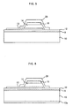
- a fifth embodiment shown in Fig. 5 is the same as the first embodiment with the exception that the gas trapping material-equipped seal housing is replaced with a sealing film 26 air-tightly sealing the entire device.
- the organic EL device has a sealing film 26 covering everything from the back face of this second display electrode 15.
- Sealing film 26, which covers from the back face of the organic EL device is an inorganic passivation film.
- multi-layering can also be done by disposing a sealing film comprising a resin on top of this inorganic passivation film.
- an inorganic passivation film comprising an inorganic material can be provided once again on the outermost surface of the resin sealing film.
- the inorganic passivation film comprises an inorganic material such as the above-mentioned silicon oxynitride, silicon nitride or some other such nitride, or an oxide or carbon.
- an inorganic material such as the above-mentioned silicon oxynitride, silicon nitride or some other such nitride, or an oxide or carbon.
- a fluorocarbon or silicon-based resin, plus a photoresist, polyimide or other such synthetic resin can be used.
- a sixth embodiment shown in Fig. 6 is the same as the second embodiment with the exception that the gas trapping material-equipped seal housing is replaced with a sealing film 26 tightly sealing the entire device.
- a seventh embodiment shown in Fig. 7 is the same as the third embodiment with the exception that the gas trapping material-equipped seal housing is replaced with a sealing film 26 tightly sealing the entire device.
- FIG. 8 An eighth embodiment shown in Fig. 8 is the same as the fourth embodiment with the exception that the gas trapping material-equipped seal housing is replaced with a sealing film 26 tightly sealing the entire device.
- the base material of either the support substrate or the color-changing substrate utilized in the present invention have greater than 50% transmittance of light in the visible region, and be a smooth substrate.
- a glass plate or a high-molecular compound plate can be cited as examples.
- glass plates there are, in particular, plates made of soda-lime glass, glass containing barium-strontium, lead glass, aluminosilicate glass, borosilicate glass, barium-borosilicate glass, and quartz.
- high-molecular compound plates there are plates made of polycarbonate, acrylic, polyethylene terephthalate, polyether sulfide, and polysulfone. Since a glass plate in particular can almost completely exclude outside air, it is preferable to use glass plates in the first, third, fifth and seventh embodiments. It is preferable to use high-molecular compound plates in the second, fourth, sixth and eighth embodiments.
- the color-changing substrate utilized in the present invention one or more predetermined fluorescent material portions are separated and arranged flatly on the surface of a predetermined base material, and each predetermined fluorescent material portion is arranged corresponding to the location of an organic EL device.
- the color-changing film utilized in the present invention can be a color filter that adjusts the color by either resolving or shading the light of a light-emitting member.
- contrast can be enhanced between the respective predetermined fluorescent material portions by excluding light from the emitted light of an organic EL device and from each predetermined fluorescent material portion, and a black matrix can be arranged to reduce dependency on the angle of visibility.
- a predetermined fluorescent material portion for example, comprises either a fluorescent dye and a resin, or a fluorescent dye alone, and a predetermined fluorescent material portion comprising a fluorescent dye and a resin is a solid in which the fluorescent dye is distributed inside either a colored resin or a binder resin.
- Concerning specific fluorescent dyes as fluorescent dyes for converting from near ultraviolet light to a blue light emission from the emitted light of a purple organic EL device there are 1, 4-bis (2-methylstyryl) benzene, trans-4, 4'-diphenylstilbene, and 7-hydroxy-4-methylcoumarin.
- fluorescent dyes for converting from the emitted light of either a blue, blue-green, or white light-emitting member to a green emitted light there are 2,3,5,6-1H, 4H-tetrahydro-8-trifluoromethylquinolizino (9,9a,1-gh) coumarin, 3-(2'-benzothiazolyl)-7-diethylaminocumarin, 3-(2'-benzimidazolyl)-7-N,N-diethylaminocumarin.
- fluorescent dyes for converting from blue to green emitted light of a light-emitting member to orange to red emitted light, there are 4-dicyanomethylene-2-methyl-6-(p-dimethylaminostyryl)-4h-pyran, and 1-ethyl-2-(4-(p-dimethylaminophenyl)-1,3-butadienyl)-pyridinium-perchlorate.
- pigmented resins such as polyester methacrylate, polyvinylchloride, vinylchloridevinylacetate copolymer, alkyd resin, aromatic sulfonamide resin, urea resin, melamine resin, and benzoguanamine resin, can be pigmented by working such fluorescent dyes into the pigmented resins in advance.
- binder resins there are, for example, the transparent materials polymethyl-methacrylate, polyacrylate, polycarbonate, polyvinyl alcohol, polyvinyl-pyrolidone, hyroxyethylcellulose, and carboxymethylcellulose.
- Fig. 9 is a partial enlarged rear view of an organic EL display panel comprising a plurality of organic EL devices in the ninth embodiment.
- the organic EL display panel as shown in the figure, is comprised of a plurality of organic EL devices, which are completely covered by sealing film 26, and which are arranged in a matrix on top of color-changing substrate 10.
- the organic EL display panel is constituted by sequentially layering column electrodes 13 comprising transparent electrode layers (anode first display electrodes), organic functional layers, and row electrodes 15 comprising metallic electrode layers that intersect with these column electrodes (second display electrodes) on a silicon oxynitride film.
- a matrix display-type display panel has an image display matrix comprising a plurality of light-emitting pixels of organic EL devices formed at the plurality of intersecting points of the column and row electrodes.
- First display electrodes 13 can be constituted from metallic bus lines, which electrically connect insular transparent electrodes in the horizontal direction.
- the organic EL display panel comprises a plurality of barrier ribs 7 disposed between the organic EL devices on the silicon oxynitride film of color-changing substrate 10.
- a sealing film 26 is formed on top of second display electrodes 15 and barrier ribs 7.
- Each organic EL device on this panel comprises a first display electrode 13, one or more organic functional layers 14 comprising a light-emitting layer comprised from an organic compound, and a second display electrode 15, which are stacked in order on top of color-changing substrate 10.
- Barrier plates 7 are disposed between organic EL devices so as to protrude from the color-changing substrate.
- the organic EL display panel can be provided with multiple layers of films of an inorganic passivation film and an organic resin sealing film as part of sealing film 26, which covers barrier ribs 7 from the back face.
- An inorganic passivation film comprising an inorganic compound can be provided once again on the uppermost surface of this resin sealing film.
- the constitution is such that the resin surface of the support substrate containing a resin material is covered by an inorganic barrier film, the degradation of a device pursuant to the penetration of oxygen and moisture from outside the device and outgases from the color filter and color-changing substrate can be held in check, making it possible to provide a highly reliable organic EL display and organic EL devices.
- Fig. 10 shows the tenth embodiment of organic EL display panel.
- the organic EL device is formed on a color filter 19 containing a resin binder formed on a support substrate 20 made of glass.
- the organic EL device is constituted by layering sequentially on top of this color filter 19 a first display electrode 13 (anode transparent electrode), one or more organic functional layers 14 comprising a light-emitting layer, which comprises an organic compound, and a second display electrode 15 (cathode metallic electrode).
- the organic EL device comprises a gas-impermeable seal housing 16, which comprises a gas trapping material 16a on the inside wall, and which is fastened by adhesive to support substrate 20, and seals the substrate together with the organic EL device.
- An inert material such as, for example, dry nitrogen (N 2 ), is filled in the space inside seal housing 16.
- N 2 dry nitrogen
- a transparent electrode comprising indium tin oxide (ITO) is formed on support substrate 20 by either vapor deposition or sputtering.
- An organic functional layer 14 is formed thereon via the sequential vapor deposition of a hole injecting layer comprising copper phthalocyanine, a hole transporting layer comprising TPD (triphenylamine derivative), a light-emitting layer comprising Alq3 (aluminum chelate complex), and an electron injecting layer comprising Li 2 O (lithium oxide).
- a metallic electrode (second display electrode) 15 comprising Al (aluminum) is formed thereon by vapor deposition so as to face the electrode pattern of transparent electrode 13.
- the eleventh embodiment shown in Fig. 11 is the same as the tenth embodiment except support substrate 20 is made of resin, and an inorganic barrier film 12 for covering the surface of the support substrate is provided between the organic EL device and the support substrate.
- the inorganic barrier film 12 may be made of silicon oxynitride for example to have a moisture-proof property. It is desirable that the nitrogen/oxygen ratio of the silicon oxynitride of the inorganic barrier film be between 0.13 and 2.88 for maintaining moisture-proofness. If it is higher than this, the residual stress of the film becomes higher, and if it is lower than this, it becomes impossible to adequately prevent the penetration of moisture and so forth into the organic functional layer of the organic EL device.
- the surface of support substrate 20, which is covered by the inorganic barrier film comprise at the least a surface that comes in contact with the organic EL devices, a surface between the organic EL devices, a surface surrounding the organic EL devices, and a surface on the other side of the surface that makes contact with the organic EL devices. This is to prevent the penetration of moisture and the like into the organic functional layers.
- a second inorganic barrier film which covers the surface on the other side of the surface that makes contact with the organic EL device in the support substrate 20.
- a twelfth embodiment shown in Fig. 12 is the same as the tenth embodiment with the exception that the gas trapping material-equipped seal housing is replaced with a sealing film 26 tightly sealing the entire device.
- the sealing region 19b including the sealing film 26 covering the end face 9a prevents invasion of water moisture to the devices from the end face 9a of the color filter 19.
- the sealing film 26, which covers from the back face of the organic EL device is an inorganic passivation film. Further, multi-layering can also be done by disposing a sealing film comprising a resin on top of this inorganic passivation film. Further, an inorganic passivation film comprising an inorganic material can be provided once again on the outermost surface of the resin sealing film.
- the inorganic passivation film comprises an inorganic material such as the above-mentioned silicon oxynitride, a silicon nitride or some other such nitride, or an oxide or carbon.
- an inorganic material such as the above-mentioned silicon oxynitride, a silicon nitride or some other such nitride, or an oxide or carbon.
- a fluorocarbon or silicon-based resin, plus a photoresist, polyimide or other such synthetic resin can be used.
- a thirteenth embodiment shown in Fig. 13 is the same as the second embodiment with the exception that the gas trapping material-equipped seal housing is replaced with a sealing film 26 air-tightly sealing the entire device.
- the color filter including the resin binder may be another film containing a resin material such as color-changing film, insulative film, smoothing film or the like.
- a structure as shown in Fig. 14 is revealed. There are formed in turn, on or over a support substrate 20, a color filter 19 having a predetermined size, an inorganic barrier film 12 covering the color filter thoroughly, a color-changing film CCM adapted to the color filter 19 and having a predetermined size, a resin overcoating film OC covering them thoroughly, and a second inorganic barrier film 12a.
- the first display electrode 13 of the organic EL device is formed on the second inorganic barrier film 12a.
- the outgas invasion into the device is prevented by such a formation that a functional member such as the color-changing film CCM, the color filter 19 etc. is embedded within the inorganic and organic multi-layer.
- the invention is constructed in such a manner that all layers constituting the devices including resin materials except a sealing material are not exposed to the outside air.
- the resin-contained film made of an organic material has a remarkable high gaseous permeability in comparison with an inorganic material and the organic EL devices are shut out within the sealing structure using the same to be non-exposure to the outside. Therefore, it is possible to effectively reduce the deterioration of organic EL devices caused by invasion of water vapor and oxygen from the outside. In addition, even if a sealing structure without use of an organic sealing material and gas trapping material is employed, organic EL devices may be in a good state of preservation.
- the base material of either the support substrate or the color-changing substrate utilized in the present invention have greater than 50% transmittance of light in the visible region, and be a smooth substrate.
- a glass plate or a high-molecular compound plate can be cited as examples.
- glass plates there are, in particular, plates made of soda-lime glass, glass containing barium-strontium, lead glass, aluminosilicate glass, borosilicate glass, barium-borosilicate glass, and quartz.
- high-molecular compound plates there are plates made of polycarbonate, acrylic, polyethylene terephthalate, polyether sulfide, and polysulfone.
- Fig. 15 is a partial enlarged rear view of an organic EL display panel comprising a plurality of organic EL devices of the fourteenth embodiment.
- the organic EL display panel as shown in the figure, is comprised of a plurality of organic EL devices, which are completely covered by sealing film 26, and which are arranged in a matrix on top of support substrate 20.
- the organic EL display panel is constituted by sequentially layering column electrodes 13 comprising transparent electrode layers (anode first display electrodes), organic functional layers, and row electrodes 15 comprising metallic electrode layers that intersect with these column electrodes (second display electrodes) on a silicon oxynitride film.
- a matrix display-type display panel has an image display matrix comprising a plurality of light-emitting pixels of organic EL devices formed at the plurality of intersecting points of the column and row electrodes.
- First display electrodes 13 can be constituted from metallic bus lines, which electrically connect insular transparent electrodes in the horizontal direction.
- the organic EL display panel comprises a plurality of barrier ribs 7 disposed between the organic EL devices on the silicon oxynitride film of support substrate 20.
- a sealing film 26 is formed on top of second display electrodes 15 and barrier ribs 7.
- Each organic EL device on this panel comprises a first display electrode 13, one or more organic functional layers 14 comprising a light-emitting layer comprised from an organic compound, and a second display electrode 15, which are stacked in order on top of support substrate 20.
- Barrier plates 7 are disposed between organic EL devices so as to protrude from the color-changing substrate.
- the organic EL display panel can be provided with multiple layers of films of an inorganic passivation film and an organic resin sealing film as part of sealing film 26, which covers barrier ribs 7 from the back face.
- An inorganic passivation film comprising an inorganic compound can be provided once again on the uppermost surface of this resin sealing film.
- sputtering was used as the method of fabricating an inorganic barrier film for shutting out moisture and the like, but it is not limited to this, and vapor growth methods, such as plasma CVD (Chemical Vapor Deposition) and vacuum deposition can also be applied.
- plasma CVD Chemical Vapor Deposition
- vacuum deposition can also be applied.
- the constitution is such that the end face of resin-contained film i.e., resin surface of the support substrate containing a resin material is covered by an inorganic barrier film, the degradation of a device pursuant to the penetration of oxygen and moisture from outside air can be reduced. Therefore, it is possible to provide a highly reliable organic EL display and organic EL devices.
Landscapes
- Physics & Mathematics (AREA)
- Optics & Photonics (AREA)
- Engineering & Computer Science (AREA)
- Manufacturing & Machinery (AREA)
- Electroluminescent Light Sources (AREA)
Applications Claiming Priority (5)
| Application Number | Priority Date | Filing Date | Title |
|---|---|---|---|
| JP2002094881A JP2003297552A (ja) | 2002-03-29 | 2002-03-29 | 有機エレクトロルミネッセンス表示パネル |
| JP2002094881 | 2002-03-29 | ||
| JP2002094880A JP2003297551A (ja) | 2002-03-29 | 2002-03-29 | 有機エレクトロルミネッセンス表示パネル |
| JP2002094880 | 2002-03-29 | ||
| PCT/JP2003/003313 WO2003084290A1 (fr) | 2002-03-29 | 2003-03-19 | Ecran d'affichage organique electroluminescent |
Publications (1)
| Publication Number | Publication Date |
|---|---|
| EP1492387A1 true EP1492387A1 (de) | 2004-12-29 |
Family
ID=28677578
Family Applications (1)
| Application Number | Title | Priority Date | Filing Date |
|---|---|---|---|
| EP20030712755 Withdrawn EP1492387A1 (de) | 2002-03-29 | 2003-03-19 | Organische elektrolumineszenzanzeigetafel |
Country Status (7)
| Country | Link |
|---|---|
| US (1) | US20050156519A1 (de) |
| EP (1) | EP1492387A1 (de) |
| KR (1) | KR20040102054A (de) |
| CN (1) | CN1643989A (de) |
| AU (1) | AU2003221089A1 (de) |
| TW (1) | TW594619B (de) |
| WO (1) | WO2003084290A1 (de) |
Cited By (7)
| Publication number | Priority date | Publication date | Assignee | Title |
|---|---|---|---|---|
| WO2007114536A1 (en) * | 2006-04-05 | 2007-10-11 | Daewoo Electronics Corporation | Organic electroluminescence device and method for manufacturing same |
| WO2009094994A1 (de) * | 2008-01-31 | 2009-08-06 | Osram Opto Semiconductors Gmbh | Optoelektronisches modul und projektionsvorrichtung mit dem optoelektronischen modul |
| US7850501B2 (en) | 2003-10-20 | 2010-12-14 | Semiconductor Energy Laboratory Co., Ltd. | Light-emitting device and method for manufacturing light-emitting device |
| US7902747B2 (en) | 2003-10-21 | 2011-03-08 | Semiconductor Energy Laboratory Co., Ltd. | Light-emitting device having a thin insulating film made of nitrogen and silicon and an electrode made of conductive transparent oxide and silicon dioxide |
| US8012529B2 (en) | 2003-08-29 | 2011-09-06 | Semiconductor Energy Laboratory Co., Ltd. | Light emitting element and manufacturing method thereof |
| WO2016174157A1 (de) * | 2015-04-29 | 2016-11-03 | Osram Oled Gmbh | Optoelektronisches halbleiterbauteil |
| WO2018028955A1 (de) * | 2016-08-09 | 2018-02-15 | Osram Oled Gmbh | Optoelektronische vorrichtung |
Families Citing this family (15)
| Publication number | Priority date | Publication date | Assignee | Title |
|---|---|---|---|---|
| SG142140A1 (en) | 2003-06-27 | 2008-05-28 | Semiconductor Energy Lab | Display device and method of manufacturing thereof |
| US7928654B2 (en) | 2003-08-29 | 2011-04-19 | Semiconductor Energy Laboratory Co., Ltd. | Display device and method for manufacturing the same |
| JP4741177B2 (ja) * | 2003-08-29 | 2011-08-03 | 株式会社半導体エネルギー研究所 | 表示装置の作製方法 |
| US20090252863A1 (en) * | 2005-07-19 | 2009-10-08 | Pioneer Corporation | Method of manufacturing protection film and method of manufacturing inorganic film |
| JPWO2007077715A1 (ja) | 2006-01-05 | 2009-06-11 | コニカミノルタホールディングス株式会社 | ボトムエミッション型有機エレクトロルミネッセンスパネル |
| KR100696557B1 (ko) * | 2006-06-02 | 2007-03-19 | 삼성에스디아이 주식회사 | 유기 발광 디스플레이 장치 |
| KR100818884B1 (ko) * | 2006-11-29 | 2008-04-01 | 성균관대학교산학협력단 | 투명성 유기/무기 다층 배리어 코팅막 형성 방법 |
| JP5332123B2 (ja) * | 2007-03-27 | 2013-11-06 | パナソニック株式会社 | 有機elモジュール |
| DE102007052181A1 (de) * | 2007-09-20 | 2009-04-02 | Osram Opto Semiconductors Gmbh | Optoelektronisches Bauelement und Verfahren zur Herstellung eines optoelektronischen Bauelements |
| JP5185598B2 (ja) * | 2007-11-06 | 2013-04-17 | 株式会社ジャパンディスプレイイースト | 有機el表示装置およびその製造方法 |
| TW201110802A (en) * | 2009-06-24 | 2011-03-16 | Seiko Epson Corp | Electro-optical device, electronic device, and illumination apparatus |
| JP2013122903A (ja) * | 2011-11-10 | 2013-06-20 | Nitto Denko Corp | 有機elデバイス、および、有機elデバイスの製造方法 |
| TWI492374B (zh) * | 2012-12-03 | 2015-07-11 | Au Optronics Corp | 電激發光顯示面板 |
| WO2016125611A1 (ja) * | 2015-02-03 | 2016-08-11 | 日本電気硝子株式会社 | 波長変換部材及びそれを用いた発光デバイス |
| CN105185810A (zh) | 2015-08-07 | 2015-12-23 | 京东方科技集团股份有限公司 | 一种显示基板及其制备方法、显示面板和显示装置 |
Family Cites Families (13)
| Publication number | Priority date | Publication date | Assignee | Title |
|---|---|---|---|---|
| US4357557A (en) * | 1979-03-16 | 1982-11-02 | Sharp Kabushiki Kaisha | Glass sealed thin-film electroluminescent display panel free of moisture and the fabrication method thereof |
| JPS63105493A (ja) * | 1986-10-22 | 1988-05-10 | アルプス電気株式会社 | 薄膜elパネル |
| US5686360A (en) * | 1995-11-30 | 1997-11-11 | Motorola | Passivation of organic devices |
| JPH10275682A (ja) * | 1997-02-03 | 1998-10-13 | Nec Corp | 有機el素子 |
| JP3224352B2 (ja) * | 1997-02-21 | 2001-10-29 | 出光興産株式会社 | 多色発光装置 |
| JPH11260562A (ja) * | 1998-03-09 | 1999-09-24 | Tdk Corp | 有機elカラーディスプレイ |
| JP2000215988A (ja) * | 1999-01-20 | 2000-08-04 | Sharp Corp | Elパネルおよびその製造方法 |
| JP4482966B2 (ja) * | 1999-08-20 | 2010-06-16 | Tdk株式会社 | El表示装置 |
| US7198832B2 (en) * | 1999-10-25 | 2007-04-03 | Vitex Systems, Inc. | Method for edge sealing barrier films |
| JP3570943B2 (ja) * | 1999-12-27 | 2004-09-29 | 三星エスディアイ株式会社 | 有機エレクトロルミネッセンス素子およびその製造方法 |
| US6576351B2 (en) * | 2001-02-16 | 2003-06-10 | Universal Display Corporation | Barrier region for optoelectronic devices |
| JP2003168555A (ja) * | 2001-11-29 | 2003-06-13 | Sumitomo Electric Ind Ltd | エレクトロルミネッセンス表示装置 |
| JP4185341B2 (ja) * | 2002-09-25 | 2008-11-26 | パイオニア株式会社 | 多層バリア膜構造、有機エレクトロルミネッセンス表示パネル及び製造方法 |
-
2003
- 2003-03-19 EP EP20030712755 patent/EP1492387A1/de not_active Withdrawn
- 2003-03-19 WO PCT/JP2003/003313 patent/WO2003084290A1/ja not_active Application Discontinuation
- 2003-03-19 AU AU2003221089A patent/AU2003221089A1/en not_active Abandoned
- 2003-03-19 KR KR10-2004-7015179A patent/KR20040102054A/ko not_active Application Discontinuation
- 2003-03-19 CN CNA038072645A patent/CN1643989A/zh active Pending
- 2003-03-19 US US10/509,079 patent/US20050156519A1/en not_active Abandoned
- 2003-03-20 TW TW092106205A patent/TW594619B/zh not_active IP Right Cessation
Non-Patent Citations (1)
| Title |
|---|
| See references of WO03084290A1 * |
Cited By (16)
| Publication number | Priority date | Publication date | Assignee | Title |
|---|---|---|---|---|
| US8012529B2 (en) | 2003-08-29 | 2011-09-06 | Semiconductor Energy Laboratory Co., Ltd. | Light emitting element and manufacturing method thereof |
| US7850501B2 (en) | 2003-10-20 | 2010-12-14 | Semiconductor Energy Laboratory Co., Ltd. | Light-emitting device and method for manufacturing light-emitting device |
| US9034675B2 (en) | 2003-10-20 | 2015-05-19 | Semiconductor Energy Laboratory Co., Ltd. | Light-emitting device and method for manufacturing light-emitting device |
| US8759131B2 (en) | 2003-10-20 | 2014-06-24 | Semiconductor Energy Laboratory Co., Ltd. | Light-emitting device and method for manufacturing light-emitting device |
| US8643030B2 (en) | 2003-10-21 | 2014-02-04 | Semiconductor Energy Laboratory Co., Ltd. | Light-emitting device |
| US7902747B2 (en) | 2003-10-21 | 2011-03-08 | Semiconductor Energy Laboratory Co., Ltd. | Light-emitting device having a thin insulating film made of nitrogen and silicon and an electrode made of conductive transparent oxide and silicon dioxide |
| US8742660B2 (en) | 2003-10-21 | 2014-06-03 | Semiconductor Energy Laboratory Co., Ltd. | Light-emitting device |
| US7678590B2 (en) | 2005-12-19 | 2010-03-16 | Daewoo Electronics Corporation | Organic electroluminescence device and method for manufacturing same |
| WO2007114536A1 (en) * | 2006-04-05 | 2007-10-11 | Daewoo Electronics Corporation | Organic electroluminescence device and method for manufacturing same |
| US7545097B2 (en) | 2006-04-05 | 2009-06-09 | Daewoo Electronics Corporation | Organic electroluminescence device and method for manufacturing same |
| US8585246B2 (en) | 2008-01-31 | 2013-11-19 | OSRAM Optosemiconductors GmbH | Optoelectronic module and projection apparatus comprising the optoelectronic module |
| WO2009094994A1 (de) * | 2008-01-31 | 2009-08-06 | Osram Opto Semiconductors Gmbh | Optoelektronisches modul und projektionsvorrichtung mit dem optoelektronischen modul |
| WO2016174157A1 (de) * | 2015-04-29 | 2016-11-03 | Osram Oled Gmbh | Optoelektronisches halbleiterbauteil |
| US10593907B2 (en) | 2015-04-29 | 2020-03-17 | Osram Oled Gmbh | Optoelectronics semiconductor component |
| US11183666B2 (en) | 2015-04-29 | 2021-11-23 | Pictiva Displays International Limited | Optoelectronic semiconductor component |
| WO2018028955A1 (de) * | 2016-08-09 | 2018-02-15 | Osram Oled Gmbh | Optoelektronische vorrichtung |
Also Published As
| Publication number | Publication date |
|---|---|
| TW200305122A (en) | 2003-10-16 |
| CN1643989A (zh) | 2005-07-20 |
| WO2003084290A1 (fr) | 2003-10-09 |
| KR20040102054A (ko) | 2004-12-03 |
| AU2003221089A1 (en) | 2003-10-13 |
| TW594619B (en) | 2004-06-21 |
| US20050156519A1 (en) | 2005-07-21 |
Similar Documents
| Publication | Publication Date | Title |
|---|---|---|
| EP1492387A1 (de) | Organische elektrolumineszenzanzeigetafel | |
| KR101045916B1 (ko) | 상부 방사 유기 발광 다이오드 패널들의 캡슐화 | |
| US7431628B2 (en) | Method of manufacturing flat panel display device, flat panel display device, and panel of flat panel display device | |
| US7332859B2 (en) | Organic luminescence device with anti-reflection layer and organic luminescence device package | |
| US6356032B1 (en) | Organic element with metallic cathode | |
| JP2002299044A (ja) | エレクトロルミネッセンス表示装置 | |
| CN102024844A (zh) | 有机发光显示设备 | |
| KR101591743B1 (ko) | 전자발광 스크린을 갖는 다색 전자 디스플레이 장치 | |
| JP2003297552A (ja) | 有機エレクトロルミネッセンス表示パネル | |
| KR100604685B1 (ko) | 유기 전계 발광 소자, 그 제조 방법 및 조명 장치 | |
| JP2003297551A (ja) | 有機エレクトロルミネッセンス表示パネル | |
| US7315117B2 (en) | Full color display panel and color-separating substrate thereof | |
| KR20050050572A (ko) | 일렉트로루미네선스 소자 및 조명장치 | |
| KR20040092420A (ko) | 유기 전계 발광 디스플레이 패널 및 그 제조 방법 | |
| US20120194061A1 (en) | Organic el device | |
| JPWO2007032515A1 (ja) | 有機エレクトロルミネセンス表示パネルおよび防湿基板 | |
| KR20090029007A (ko) | 유기발광소자 및 그 구동방법 | |
| US20090015146A1 (en) | Organic el display device | |
| KR100648713B1 (ko) | 유기 전계 발광소자 및 그의 제조 방법 | |
| KR100672417B1 (ko) | 유기 el 소자 | |
| KR20070070119A (ko) | El 패널 및 이의 제조방법 | |
| KR100626000B1 (ko) | 전계 발광 디스플레이 장치 | |
| KR100700719B1 (ko) | 고휘도 백색 및 단색광 유기 전계 다중면 발광 장치 | |
| JP2006086084A (ja) | 自発光パネルの製造方法 | |
| JP2005259573A (ja) | 有機elパネルとその製造方法 |
Legal Events
| Date | Code | Title | Description |
|---|---|---|---|
| PUAI | Public reference made under article 153(3) epc to a published international application that has entered the european phase |
Free format text: ORIGINAL CODE: 0009012 |
|
| 17P | Request for examination filed |
Effective date: 20040922 |
|
| AK | Designated contracting states |
Kind code of ref document: A1 Designated state(s): AT BE BG CH CY CZ DE DK EE ES FI FR GB GR HU IE IT LI LU MC NL PT RO SE SI SK TR |
|
| AX | Request for extension of the european patent |
Extension state: AL LT LV MK |
|
| STAA | Information on the status of an ep patent application or granted ep patent |
Free format text: STATUS: THE APPLICATION IS DEEMED TO BE WITHDRAWN |
|
| 18D | Application deemed to be withdrawn |
Effective date: 20071105 |