EP1489397A1 - Thermomètre de rayonnement - Google Patents
Thermomètre de rayonnement Download PDFInfo
- Publication number
- EP1489397A1 EP1489397A1 EP04021010A EP04021010A EP1489397A1 EP 1489397 A1 EP1489397 A1 EP 1489397A1 EP 04021010 A EP04021010 A EP 04021010A EP 04021010 A EP04021010 A EP 04021010A EP 1489397 A1 EP1489397 A1 EP 1489397A1
- Authority
- EP
- European Patent Office
- Prior art keywords
- sensor
- temperature
- measurement
- output
- infrared ray
- Prior art date
- Legal status (The legal status is an assumption and is not a legal conclusion. Google has not performed a legal analysis and makes no representation as to the accuracy of the status listed.)
- Ceased
Links
- 230000005855 radiation Effects 0.000 title claims abstract description 49
- 238000005259 measurement Methods 0.000 claims abstract description 145
- 230000001419 dependent effect Effects 0.000 claims description 53
- 238000001514 detection method Methods 0.000 description 7
- 239000000523 sample Substances 0.000 description 7
- 230000006870 function Effects 0.000 description 5
- 238000000034 method Methods 0.000 description 4
- 238000012545 processing Methods 0.000 description 4
- 238000010586 diagram Methods 0.000 description 3
- 239000000463 material Substances 0.000 description 3
- 238000009529 body temperature measurement Methods 0.000 description 2
- 239000004973 liquid crystal related substance Substances 0.000 description 2
- 230000000717 retained effect Effects 0.000 description 2
- 230000035945 sensitivity Effects 0.000 description 2
- 230000036760 body temperature Effects 0.000 description 1
- 238000006243 chemical reaction Methods 0.000 description 1
- 238000006073 displacement reaction Methods 0.000 description 1
- 238000005516 engineering process Methods 0.000 description 1
- 239000007769 metal material Substances 0.000 description 1
- 238000012986 modification Methods 0.000 description 1
- 230000004048 modification Effects 0.000 description 1
- 238000011160 research Methods 0.000 description 1
- 230000000452 restraining effect Effects 0.000 description 1
- 239000004065 semiconductor Substances 0.000 description 1
- 210000003454 tympanic membrane Anatomy 0.000 description 1
Images


Classifications
-
- G—PHYSICS
- G01—MEASURING; TESTING
- G01J—MEASUREMENT OF INTENSITY, VELOCITY, SPECTRAL CONTENT, POLARISATION, PHASE OR PULSE CHARACTERISTICS OF INFRARED, VISIBLE OR ULTRAVIOLET LIGHT; COLORIMETRY; RADIATION PYROMETRY
- G01J5/00—Radiation pyrometry, e.g. infrared or optical thermometry
- G01J5/02—Constructional details
- G01J5/026—Control of working procedures of a pyrometer, other than calibration; Bandwidth calculation; Gain control
-
- G—PHYSICS
- G01—MEASURING; TESTING
- G01J—MEASUREMENT OF INTENSITY, VELOCITY, SPECTRAL CONTENT, POLARISATION, PHASE OR PULSE CHARACTERISTICS OF INFRARED, VISIBLE OR ULTRAVIOLET LIGHT; COLORIMETRY; RADIATION PYROMETRY
- G01J5/00—Radiation pyrometry, e.g. infrared or optical thermometry
- G01J5/02—Constructional details
- G01J5/06—Arrangements for eliminating effects of disturbing radiation; Arrangements for compensating changes in sensitivity
- G01J5/064—Ambient temperature sensor; Housing temperature sensor; Constructional details thereof
-
- G—PHYSICS
- G01—MEASURING; TESTING
- G01J—MEASUREMENT OF INTENSITY, VELOCITY, SPECTRAL CONTENT, POLARISATION, PHASE OR PULSE CHARACTERISTICS OF INFRARED, VISIBLE OR ULTRAVIOLET LIGHT; COLORIMETRY; RADIATION PYROMETRY
- G01J5/00—Radiation pyrometry, e.g. infrared or optical thermometry
- G01J5/10—Radiation pyrometry, e.g. infrared or optical thermometry using electric radiation detectors
- G01J5/12—Radiation pyrometry, e.g. infrared or optical thermometry using electric radiation detectors using thermoelectric elements, e.g. thermocouples
- G01J5/14—Electrical features thereof
- G01J5/16—Arrangements with respect to the cold junction; Compensating influence of ambient temperature or other variables
-
- G—PHYSICS
- G01—MEASURING; TESTING
- G01J—MEASUREMENT OF INTENSITY, VELOCITY, SPECTRAL CONTENT, POLARISATION, PHASE OR PULSE CHARACTERISTICS OF INFRARED, VISIBLE OR ULTRAVIOLET LIGHT; COLORIMETRY; RADIATION PYROMETRY
- G01J5/00—Radiation pyrometry, e.g. infrared or optical thermometry
- G01J5/70—Passive compensation of pyrometer measurements, e.g. using ambient temperature sensing or sensing of temperature within housing
Definitions
- This invention relates to a radiation thermometer for measuring the temperature of an object of measurement by infrared ray radiated from the object of measurement.
- the clinical thermometer comprises an infrared ray sensor, a probe for taking in infrared ray from an earhole, and a controller for maintaining a sensor temperature of an infrared sensor at a predetermined temperature, and calculates a temperature from an output of the infrared ray sensor and the sensor temperature of the infrared ray sensor maintained at a predetermined temperature.
- thermometer calculates a temperature from a measured sensor temperature of an infrared ray sensor and an output of an infrared sensor by measuring temperature of the infrared sensor (sensor temperature) in stead of maintaining it.
- a temperature of an object of measurement is calculated in accordance with the following logical expression (equation 1) derived from a rule generally known as the Rule of Stefan-Boltzmann (see, for example, "infrared radiation engineering: basics and applications” edited by Infrared Ray Technology Research Institute and published by Ohmsha, Ltd.):
- Output of infrared ray sensor E L(Tx 4 -Ta 4 ) where, Tx is an absolute temperature of an object of measurement (an object of measurement temperature); Ta is an absolute temperature of an infrared ray sensor (a sensor temperature); E is an output of an infrared ray sensor (a sensor output); and L is a coefficient indicating the sensitivity of a measurement system.
- a sensor temperature was preserved at a reference temperature Ta0, an object of measurement having a known object of measurement reference temperature T0 was measured, and a measurement value was adjusted in accordance with a logical expression such as equation 1 using a calculated sensor output E0. That is to say, during an adjustment, controlling means incorporated in the radiation thermometer determined a coefficient L that could be measured most precisely in accordance with the equation shown by the straight line 101 of Fig. 8 from the above (T0, Ta0, E0), and retained the coefficient in a readable memory from the controlling means.
- the controlling means incorporated in the radiation thermometer read out the coefficient L from the memory and calculated the temperature of the object of measurement in accordance with equation 1 from a sensor output E and a sensor temperature Ta of the infrared ray sensor.
- the present invention has been devised to solve the above mentioned object and it is an object of the present invention to provide a radiation thermometer capable of precise measurement without depending on an absolute precision of an infrared ray sensor for detecting infrared ray or a temperature sensor for measuring a temperature of the infrared ray sensor.
- a radiation thermometer of the present invention has the following configuration.
- a radiation thermometer of the present invention comprises an infrared ray sensor for detecting infrared ray radiated from an object of measurement as a sensor output, a sensor temperature measuring portion for measuring the temperature of the infrared ray sensor itself as a sensor temperature, a controlling means for calculating the temperature of the object of measurement as an object of measurement temperature based on the sensor output and the sensor temperature, wherein the controlling means for controlling the temperature measurement retains information for an object of measurement reference temperature as an object of measurement temperature to be a reference, information for a sensor reference temperature as a sensor temperature to be a reference, and information for a sensor reference output as a sensor output to be a reference when infrared ray radiated from the object of measurement having the object of measurement reference temperature is detected by the infrared ray sensor having the sensor reference temperature, and calculates the object of measurement temperature of the object of measurement based on a first difference as a difference between a sensor
- the controlling means may retain the variation characteristics of an object of measurement temperature specified by the combination of object of measurement temperatures at a plurality of points measured in advance, a sensor temperature and a sensor output, and calculate the obj ect of measurement temperature based on the variation amount of the object of measurement temperature by the first difference, the variation amount of the object of measurement temperature by the second difference, and the information for an object of measurement reference temperature.
- controlling means may further retain sensor temperature dependent amount calculation information found based on the relationship between each sensor output at the time when the infrared ray sensor detects infrared ray from an object of measurement having a specific object of measurement temperature at different sensor temperatures at a plurality of points, respectively, and each sensor temperature at that time and sensor output dependent amount calculation information found based on the relationship between each sensor output at the time when the infrared ray sensor detects infrared ray from an object of measurement having different object of measurement temperatures of a plurality of points at a specific sensor temperature, respectively, and each object of measurement temperature at that time, and calculate the temperature of the object of measurement based on a relative sensor temperature dependent amount to be calculated based on the first difference and the sensor temperature dependent amount calculation information, a relative sensor output dependent amount calculated based on the second difference and the sensor output dependent amount calculation information, and information for the object of measurement reference temperature.
- a sensor reference output at the time when an object of measurement to be a reference having an object of measurement reference temperature is measured by an infrared ray sensor placed under a sensor reference temperature is calculated first in advance. Then, when an object of measurement with an unknown object of measurement temperature is measured at a specific sensor temperature and a specific sensor output is found, the object of measurement temperature of the object of measurement is calculated based on each difference of the sensor temperature and the sensor output from the sensor reference temperature and the sensor reference output.
- a variation amount for the sensor temperature i.e., a relative sensor temperature dependent amount
- a measurement temperature attributable to the sensor output may be calculated in accordance with the logical expression (equation 1).
- a variation amount for the sensor output i.e., a relative sensor output dependent amount
- a measurement temperature attributable to the sensor temperature may be calculated in accordance with the logical expression (equation 1).
- the temperature measuring means may be equipped with a thermistor or a diode.
- the infrared ray detecting means may be equipped with a thermopile or a pyroelectric sensor.
- the variation characteristics may be composed of a biquadratic or less polynominal of one or both of a sensor temperature value and a sensor output value
- the sensor temperature dependent amount calculation information may be represented by a coefficient composing a biquadratic or less polynominal of a sensor temperature value
- the sensor output dependent amount calculation information may be represented by a coefficient composing a biquadratic or less polynominal of a sensor output value.
- FIG. 1 is a block diagram of a radiation thermometer in accordance with Embodiment 1 of the present invention
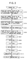
- Fig. 2 is a flow chart showing its operation
- Fig. 5 is a graph showing a measurement principle of the present invention
- Fig. 6 is a graph showing the relationship between the detection characteristics and a sensor output of the radiation thermometer of this embodiment
- Fig. 7 is a graph showing the relationship between the detection characteristics and a sensor temperature of the radiation thermometer.
- FIG. 1 A block diagram showing the configuration of this radiation thermometer is shown in Fig. 1.
- This radiation thermometer is equipped with an infrared ray sensor 1 for detecting infrared ray radiated from an earhole, a temperature sensor 2 (corresponding a sensor temperature measuring portion) for measuring the temperature of the infrared ray sensor 1 itself (sensor temperature) , a probe (not shown) to be inserted in an earhole for guiding infrared ray from the eardrum and its vicinity to the infrared ray sensor 1, an amplifier 3 for receiving and amplifying an output of the infrared ray sensor 1 (sensor output) and an A/D converter 4 for converting an output of the sensor 1 and an output of the temperature sensor 2 that have been amplified by the amplifier 3 to digital amounts.
- an infrared ray sensor 1 for detecting infrared ray radiated from an earhole
- a temperature sensor 2 corresponding a sensor temperature measuring portion
- a probe (not shown) to be inserted
- the radiation thermometer has a CPU 5 for controlling a measuring sequence and the above mentioned A/D converter 4, a power switch 7 for turning on or off a power source, a measurement starting switch 8 which instructs the start of measurement, a memory 9, and a liquid crystal display 6 are connected to the CPU 5.
- thermopile is used as the infrared ray sensor 1.
- the infrared ray sensor 1 is disposed in the depth of the probe together with the temperature sensor 2.
- An output of the infrared ray sensor 1 is input in the amplifier 3 and amplified, converted to digital signals by the A/D converter 4, and taken in the CPU 5.
- the temperature sensor 2 touches the infrared ray sensor 1 in order to measure the temperature of the infrared ray sensor 1.
- An output of the temperature sensor 2 is converted to digital signals by the A/D converter 4 as it is, and sent to the CPU 5.
- a thermistor is used as the temperature sensor 2. Therefore, in this embodiment, the sensor temperature of the infrared ray sensor 1 measured by the temperature sensor 2 is shown as a resistance value R of the thermistor.
- the CPU 5 calculates (as corresponding to a controlling means) the temperature Tx of an object of measurement from the output E of the infrared ray sensor 1 and the output Ta of the temperature sensor 2 (or the resistance value R of the thermistor) by the execution of a control program stored in the memory 9.
- the temperature corresponds to the object of measurement temperature.
- the CPU 5 calculates the difference ⁇ E of the sensor output E with respect to the sensor reference output E0 and the difference ⁇ Ta (the difference ⁇ R of the resistance value of the temperature sensor 2) of the sensor temperature with respect to the sensor reference temperature Ta0 (the output R0 of the temperature sensor 2), and relatively calculates the object of measurement temperature Tx from the differences.
- This corresponds to calculating the object of measurement temperature Tx of an object of measurement by the displacement indicated by an arrow 102 in the area indicated by the above difference in the vicinity of the reference point (E0, Ta0) on the graph of the detection characteristics of the actually measured radiation thermometer indicated by a dotted line 100 shown in Fig. 5 (this is hereinafter referred to as the variation characteristics).
- the present invention provides a radiation thermometer for measuring the temperature of an object of measurement in accordance with the below equation 2 instead of the conventional equation 1.
- Temperature Tx T0 + f( ⁇ Ta) + g( ⁇ E) where, T0 is an object of measurement reference temperature of an object of measurement; ⁇ Ta is a difference from the sensor reference temperature of the sensor temperature of the infrared ray sensor 1.
- the sensor temperature is generally given as its resistance value R, and the difference of the sensor temperature is given as the difference ⁇ R of the resistance value R from the reference resistance value R0;
- ⁇ E is a difference of the sensor output of the infrared ray sensor 1 from the sensor reference output;
- f is a function indicating contribution to the measured temperature when the sensor temperature is changed (corresponding to the sensor temperature dependent amount calculation information).
- Infrared ray from an object of measurement to be a reference having a specific temperature can be experimentally calculated based on the relationship between the sensor output of the infrared ray sensor 1 at the time when it is detected at different sensor temperatures of a plurality of points and the sensor temperature at that time; f( ⁇ Ta) is a relative sensor temperature dependent amount.
- f( ⁇ Ra) is a relative sensor temperature dependent amount.
- g is a contribution to the measured temperature when the sensor output is changed (corresponding to the sensor output dependent amount calculation information).
- Infrared ray from an object of measurement to be a reference at different object of measurement temperatures at a plurality of points can be experimentally calculated based on the relationship between the sensor output of the infrared ray sensor 1 at the time when it is detected at a specific sensor temperature and the object of measurement temperature at that time; and g( ⁇ E) is a relative sensor output dependent amount.
- Equation 3 is shown below, in which the sensor temperature Ta of equation 2 is rewritten as the output resistance R of the thermistor being the temperature sensor 2.
- a radiation thermometer in accordance with this embodiment measures a temperature in accordance with this equation 3.
- the variation characteristics as shown in Fig. 6 and Fig. 7 is found for each radiation thermometer that is an object of adjustment by fixing one of the sensor output E and the sensor temperature Ta (the output R of the temperature sensor 2) at the reference point (E0, Ta0), and by changing the other and measuring the temperature of an object of measurement whose temperature is known.
- T0 the object of measurement reference temperature
- E0 the sensor reference output
- the sensor temperature is fixed at the sensor reference temperature Ta0 (the output of the temperature sensor 2 is the reference resistance value R0), the temperature Tx of the object of measurement is changed and the variation amount of the variation ⁇ E of the sensor output at that time is measured and plotted as shown in Fig. 6.
- the function g to be found as an experimental equation of the graph shown in Fig. 6 has variation characteristics dependent on the sensor output, it corresponds to the sensor output dependent amount calculation information.
- the temperature of an object of measurement is fixed at the object of measurement reference temperature T0, the sensor temperature Ta (the output of the temperature sensor 2 to be detected at this time is the resistance R) is changed and the variation amount of the variation ⁇ E of the sensor output at that time is measured and plotted as shown in Fig. 7.
- the axis of ordinates represents the contribution ⁇ E to the sensor output in Fig. 7, it is necessary to convert the unit to a temperature when the contribution to the measured temperature is found. Since this function f is the variation characteristics that is dependent upon the sensor temperature, it corresponds to the sensor temperature dependent amount calculation information.
- the experimental equation shown in Fig. 6 or Fig. 7 can be found with a linear or quadric expression or more advanced polynominal and the like by collecting experimental values as described above, and using such method as the minimum square method. However, considering the load on the CPU 5 due to the complexity of calculation, a biquadratic or less polynominal is preferred.
- These experimental equations show the detection characteristics of the temperature measurement each radiation thermometer has, but since it is calculated as a relative value from the reference point (E0, Ta0), it is called "variation characteristics".
- the CPU 5 retains a coefficient defining the variation characteristics found in this way in the memory 9 (A coefficient of the variation characteristics to be found from Fig. 6 is the sensor output dependent amount calculation information and a coefficient of the variation characteristics to be found from Fig. 7 whose unit is converted to the measured temperature corresponds to the sensor temperature dependent amount calculation information).
- the CPU 5 At the measurement step of the object of measurement temperature of an object of measurement, the CPU 5 first calculates relative values of the sensor output E of the infrared ray sensor 1 and the output R of the temperature sensor 2 from the reference point (E0, R0). Then, the CPU 5 calculates a sensor output dependent amount and a sensor temperature dependent amount that are variation amounts to the object of measurement reference temperature T0 used as a reference from the sensor output dependent amount calculation information and the sensor temperature dependent amount calculation information retained in the memory 9, and can calculate the object of measurement temperature Tx of an object of measurement.
- step 101 when the power switch 1 is turned on (step 101, hereinafter abbreviated as S101), the CPU 5 reads out the sensor reference output E0 of the infrared ray sensor 1 at the time of adjustment from the memory 9 (S102). The CPU 5 then reads out the output (reference resistance value) R0 of the temperature sensor 2 at the sensor reference temperature Ta0 from the memory 9 (S103). Further, the CPU 5 reads out the object of measurement reference temperature T0 at the time of adjustment from the memory 9 (S104).
- a probe (not shown) of the radiation thermometer is inserted into an earhole and the measurement switch 8 is pressed to start the measurement (S105), and the CPU 5 takes in the output E of the infrared ray sensor 1 and the output R of the temperature sensor 2 through the A/D converter 4 (S106).
- the CPU 5 then calculates the difference ⁇ R from the reference resistance value R0 of the output R of the temperature sensor 2 (S107).
- the CPU 5 then calculates the difference ⁇ E from the sensor reference output E0 of the output E of the infrared ray sensor 1 (S108).
- the CPU 5 further finds the sensor output dependent amount g ( ⁇ E) from the difference ⁇ E of the output of the infrared ray sensor 1 and adds it to the sensor temperature dependent amount E1 by the temperature sensor 2 to designate it as E2 (S110), finds the measurement temperature variation amount ⁇ T by converting the unit of E2 being the added result of the sensor temperature dependent amount and the sensor output dependent amount to temperature (S111), and finds the temperature Tx of an object of measurement by adding the found relative variation amount ⁇ T of the object of measurement temperature to the object of measurement reference temperature T0 (S112).
- the temperature of an object of measurement is measured as a relative amount from the object of measurement reference temperature T0 at the time of adjustment, it becomes possible to lessen the influence of the absolute precision of the infrared ray sensor 1 and the temperature sensor 2 and a radiation thermometer with high precision that is stable without depending upon the characteristics of each sensor can be provided.
- This is for finding a relative variation amount from the reference point (E0, Ta0) (corresponding to the arrow 102 of Fig. 5) on the actually measured variation characteristics (the dotted line graph 100 of Fig. 5, the straight line 103 of Fig. 6 and the straight line 104 of Fig. 7) in Fig. 5 through Fig. 7. Therefore, comparing with the case where it is found by the straight line 101 of Fig. 5 indicated by the logical expression (equation 1), both of the detection sensitivity corresponding to the coefficient L and the gap of the E axis at the origin are precisely adjustable.
- the difference ⁇ R of the output of the temperature sensor is once converted to the output variation E1 of the infrared ray sensor when the relative variation amount ⁇ T of the temperature of an object of measurement is found in this embodiment, this is only an example for converting a unit and the present invention is not limited to this processing.
- the temperature Tx can be found by directly converting the unit of the difference ⁇ E of the output of the infrared ray sensor 1 and the difference ⁇ R of the output of the temperature sensor 2 to the relative temperature variation of an object of measurement and adding each of them to the object of measurement reference temperature T0 (method of calculation as in equation 3).
- the present invention is not limited by the order of unit conversion, but may ultimately find the relative variation amount to the object of measurement reference temperature T0 by adding the contribution by the difference ⁇ E of the output of the infrared ray sensor 1 and the contribution by the difference ⁇ R of the output of the temperature sensor 2 after making each unit identical.
- data at a plurality of adjustment points may be stored in the memory 9 and selected to be used in accordance with an object of measurement, or combined to data of a plurality of adjustment points (T0, E0, Ta0).
- thermopile is used as the infrared ray sensor 1 in this embodiment, a pyroelectric sensor may be used.
- the temperature sensor 2 of the present invention is not limited to a thermistor but may use other temperature measuring resistant materials (metal materials with known temperature coefficient of resistance), a semiconductor sensor such as a diode, or a thermocouple.
- the temperature sensor 2 is directly converted by the A/D converter 4 in this embodiment, it may be amplified by an amplifier in advance when the output of the temperature sensor 2 is weak.
- Embodiment 1 applies the present invention to a thermometer with a probe as an element, but the implementation of the present invention is not limited to this.
- the present invention can be implemented in the measurement of a temperature other than a human body temperature, in such cases as the measurement of geothermal temperature or the measurement of temperature based on infrared ray radiation from a specific object of measurement under exposure to the atmosphere.
- the present invention is not limited to a physical configuration for each sensor to detect a signal, but has a feature in the operation for processing a signal taken from each sensor.
- a radiation thermometer of Embodiment 1 finds differences from a reference value for outputs from both of the infrared ray sensor 1 and the temperature sensor 2, and calculates a sensor temperature dependent amount and a sensor output dependent amount for the object of measurement reference temperature T0 based on these differences to find the temperature of an object of measurement.
- the temperature of an object of measurement may be measured based on a relative sensor temperature dependent amount calculated by the sensor temperature dependent amount calculation information from the difference of a sensor temperature measured by the sensor temperature measuring portion from the sensor reference temperature when an object of measurement is measured, and the sensor output of the infrared ray sensor 1.
- T(Ta, E) is an equation for finding the temperature of an object of measurement pursuant to the Rule of Stefan-Boltzmann.
- T(Ta, E) (E/L + Ta 4 ) 1/4
- Ta0 is a sensor reference temperature of the infrared ray sensor 1
- ⁇ Ta is a difference from the sensor reference temperature of the sensor temperature of the infrared ray sensor
- f( ⁇ Ta, E) is a relative sensor temperature dependent amount.
- infrared ray from an object of measurement to be a reference having a specific temperature can be experimentally found based on the relationship between the sensor output of the infrared ray sensor 1 when detected at different sensor temperatures at a plurality of points and its sensor temperature.
- equation 5 in which the sensor temperature Ta in the above equation 4 is rewritten as the output R of the thermistor being the temperature sensor 2 is shown below.
- a radiation thermometer of this embodiment is for calculating a temperature in accordance with this equation 5 with the CPU 5 executing a control program.
- the relative sensor temperature dependent amount f( ⁇ R, E0) is represented by "f( ⁇ R)". Temperature Tx ⁇ T(R0, E) + f( ⁇ R)"
- Embodiment 2 has the identical configuration and operation other than a control program to be executed by the CPU 5 with Embodiment 1 and is described if necessary using Fig. 1.
- the temperature sensor 2 has measured an object of measurement of the object of measurement reference temperature T0 and found the sensor reference output E0 of the infrared ray sensor 1 at the sensor reference temperature Ta0 (at this time, the output of the temperature sensor 2 is the reference resistance value R0).
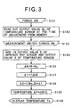
- Fig. 3 is a flow chart showing Embodiment 2 of the present invention.
- the CPU 5 reads out the output R0 of the temperature sensor 2 at the time of adjustment from the memory (S122).
- the measurement switch 8 is pressed to start the measurement (S123).
- the CPU 5 takes in the output E of the infrared ray sensor 1 and the output R of the temperature sensor 2 through the A/D converter 4 (S124).
- a radiation thermometer of the above Embodiment 2 is for finding the sensor temperature dependent amount from the difference of the output R of the temperature sensor 2 from the reference resistance value R0 and measuring the temperature of an object of measurement by the sensor temperature dependent amount and the sensor output E of the infrared ray sensor 1.
- the temperature of an object of measurement may be measured based on the relative sensor output dependent amount calculated based on the sensor output dependent amount calculation information from the difference of the sensor output to be detected by the infrared ray sensor 1 at the time of measuring an object of measurement in accordance with the sensor reference output and the sensor temperature measured by the sensor temperature measuring portion.
- E0 is a sensor reference output of the infrared ray sensor 1
- ⁇ E is a difference of the sensor output from the sensor reference output
- g(Ta, ⁇ E) is a relative sensor output dependent amount. Since g (Ta0, ⁇ E) with the sensor temperature Ta fixed at Ta0 can be used when the function g is not largely dependent upon Ta, infrared ray from an object of measurement to be a reference at different object of measurement temperatures at a plurality of points can be experimentally found based on the relationship between the sensor output of the infrared ray sensor 1 when detected at a specific sensor temperature and the object of measurement temperature at that time.
- equation 7 in which the sensor temperature Ta in the above equation 6 is rewritten as the output R of the thermistor being the temperature sensor 2 is shown below (further Ta0 is rewritten as R0).
- the CPU 5 executes a control program and calculates a temperature in accordance with this equation 7.
- g(R0, ⁇ E) is represented by "g( ⁇ E)”.
- Embodiment 2 has the identical configuration and operation other than a control program to be executed by the CPU 5 with the Embodiment 1 and is described using Fig. 1 if necessary.
- the temperature sensor 2 has measured an object of measurement of the object of measurement reference temperature T0 and found the sensor reference output E0 of the infrared ray sensor 1 at the sensor reference temperature Ta0(at this time, the output of the temperature sensor 2 is the reference resistance value R0).
- Fig. 4 is a flow chart showing Embodiment 3 of the present invention.
- a radiation thermometer of the flow chart shown in Fig. 4 similar to Embodiment 1, when the power switch 1 is turned on (S141), the CPU 5 reads out the sensor reference output E0 of the infrared ray sensor 1 at the time of adjustment from the memory 9 (S142).
- the CPU calculates the difference ⁇ E of the output E of the infrared ray sensor 1 from the sensor reference output E0 (S146).
- the CPU further finds the sensor output dependent amount g( ⁇ E) from the difference ⁇ E of the output of the infrared ray sensor 1 using the variation characteristics (corresponding to the sensor output dependent amount calculation information) found from the result of Fig. 6, and finds E2 by adding it to E1 (S148), finds the temperature Tx by converting E2 to a temperature (S149) and displays the finally found temperature on a liquid crystal display (S150).
- a radiation thermometer in accordance with the present invention does not rely on the improvement of the absolute precision based on a logical expression but measures the variation amount from a reference point and calculates a relative temperature based on the variation amount, precise measurement becomes possible without depending on the absolute precision of an infrared ray sensor or a temperature sensor.
- thermometer a radiation thermometer
Landscapes
- Physics & Mathematics (AREA)
- General Physics & Mathematics (AREA)
- Spectroscopy & Molecular Physics (AREA)
- Radiation Pyrometers (AREA)
- Measuring And Recording Apparatus For Diagnosis (AREA)
Applications Claiming Priority (3)
| Application Number | Priority Date | Filing Date | Title |
|---|---|---|---|
| JP17333699 | 1999-06-18 | ||
| JP17333699A JP3873528B2 (ja) | 1999-06-18 | 1999-06-18 | 放射体温計 |
| EP00112812A EP1061348B1 (fr) | 1999-06-18 | 2000-06-16 | Thermomètre de rayonnement |
Related Parent Applications (1)
| Application Number | Title | Priority Date | Filing Date |
|---|---|---|---|
| EP00112812A Division EP1061348B1 (fr) | 1999-06-18 | 2000-06-16 | Thermomètre de rayonnement |
Publications (1)
| Publication Number | Publication Date |
|---|---|
| EP1489397A1 true EP1489397A1 (fr) | 2004-12-22 |
Family
ID=15958551
Family Applications (3)
| Application Number | Title | Priority Date | Filing Date |
|---|---|---|---|
| EP04021009A Withdrawn EP1489396A1 (fr) | 1999-06-18 | 2000-06-16 | Thermomètre de rayonnement |
| EP00112812A Expired - Lifetime EP1061348B1 (fr) | 1999-06-18 | 2000-06-16 | Thermomètre de rayonnement |
| EP04021010A Ceased EP1489397A1 (fr) | 1999-06-18 | 2000-06-16 | Thermomètre de rayonnement |
Family Applications Before (2)
| Application Number | Title | Priority Date | Filing Date |
|---|---|---|---|
| EP04021009A Withdrawn EP1489396A1 (fr) | 1999-06-18 | 2000-06-16 | Thermomètre de rayonnement |
| EP00112812A Expired - Lifetime EP1061348B1 (fr) | 1999-06-18 | 2000-06-16 | Thermomètre de rayonnement |
Country Status (5)
| Country | Link |
|---|---|
| US (1) | US6609824B1 (fr) |
| EP (3) | EP1489396A1 (fr) |
| JP (1) | JP3873528B2 (fr) |
| DE (1) | DE60025662T2 (fr) |
| ES (1) | ES2254074T3 (fr) |
Cited By (1)
| Publication number | Priority date | Publication date | Assignee | Title |
|---|---|---|---|---|
| CN112097922A (zh) * | 2020-09-22 | 2020-12-18 | 深圳铯敏发科技有限公司 | 一种基于热电堆红外测温模组 |
Families Citing this family (11)
| Publication number | Priority date | Publication date | Assignee | Title |
|---|---|---|---|---|
| WO2001096825A1 (fr) * | 2000-06-13 | 2001-12-20 | Omron Corporation | Pyrometre |
| US7014358B2 (en) * | 2001-02-19 | 2006-03-21 | Braun Gmbh | Radiation thermometer comprising a heated measuring tip |
| US7140768B2 (en) * | 2002-07-15 | 2006-11-28 | Cold Chain Technologies, Inc. | System and method of monitoring temperature |
| US7507019B2 (en) | 2006-05-19 | 2009-03-24 | Covidien Ag | Thermometer calibration |
| US7549792B2 (en) | 2006-10-06 | 2009-06-23 | Covidien Ag | Electronic thermometer with selectable modes |
| DE102008031406B4 (de) * | 2008-07-02 | 2015-12-31 | Frank Schmidt | Empfängervorrichtung, Verwendung einer Empfängervorrichtung, System sowie Verfahren zum energiearmen Empfang von Daten |
| CN101596102B (zh) * | 2009-07-03 | 2011-10-12 | 中山市创源电子有限公司 | 一种快速测量耳温枪 |
| JP6318599B2 (ja) * | 2013-12-17 | 2018-05-09 | 株式会社リコー | 半導体集積回路 |
| CN104068832A (zh) | 2014-06-20 | 2014-10-01 | 京东方科技集团股份有限公司 | 一种体表温度计及可佩戴显示装置 |
| EP3312579B1 (fr) * | 2016-10-19 | 2022-09-14 | Melexis Technologies NV | Capteur infrarouge destiné à mesurer la température de l'air ambiant |
| CN110974186B (zh) * | 2018-10-02 | 2022-08-30 | 希尔-罗姆服务公司 | 用于确定目标区域温度变化的温度监测系统和方法 |
Citations (4)
| Publication number | Priority date | Publication date | Assignee | Title |
|---|---|---|---|---|
| EP0446788A1 (fr) * | 1990-03-12 | 1991-09-18 | Ivac Corporation | Système pour déterminer la température et pour la calibration dans un thermomètre biomédical |
| WO1993003666A1 (fr) * | 1991-08-20 | 1993-03-04 | Diatek, Incorporated | Thermometre infrarouge et son procede d'etalonnage |
| US5293877A (en) * | 1990-12-12 | 1994-03-15 | Sherwood Ims, Inc. | Body temperature thermometer and method fo measuring human body temperature utilizing calibration mapping |
| DE19613229A1 (de) * | 1996-04-02 | 1997-10-09 | Braun Ag | Verfahren zur Kalibrierung eines Strahlungsthermometers |
Family Cites Families (5)
| Publication number | Priority date | Publication date | Assignee | Title |
|---|---|---|---|---|
| USRE34507E (en) * | 1988-04-12 | 1994-01-11 | Citizen Watch Co., Ltd. | Radiation clinical thermometer |
| US5012813A (en) * | 1988-12-06 | 1991-05-07 | Exergen Corporation | Radiation detector having improved accuracy |
| CN1168090A (zh) * | 1995-11-13 | 1997-12-17 | 西铁城钟表股份有限公司 | 辐射体温计 |
| JP3805039B2 (ja) * | 1996-11-14 | 2006-08-02 | シチズン時計株式会社 | 放射体温計 |
| AU7807898A (en) * | 1997-06-03 | 1998-12-21 | Trutek, Inc. | Tympanic thermometer with modular sensing probe |
-
1999
- 1999-06-18 JP JP17333699A patent/JP3873528B2/ja not_active Expired - Lifetime
-
2000
- 2000-06-16 EP EP04021009A patent/EP1489396A1/fr not_active Withdrawn
- 2000-06-16 ES ES00112812T patent/ES2254074T3/es not_active Expired - Lifetime
- 2000-06-16 DE DE60025662T patent/DE60025662T2/de not_active Expired - Lifetime
- 2000-06-16 EP EP00112812A patent/EP1061348B1/fr not_active Expired - Lifetime
- 2000-06-16 EP EP04021010A patent/EP1489397A1/fr not_active Ceased
- 2000-06-19 US US09/597,690 patent/US6609824B1/en not_active Expired - Lifetime
Patent Citations (4)
| Publication number | Priority date | Publication date | Assignee | Title |
|---|---|---|---|---|
| EP0446788A1 (fr) * | 1990-03-12 | 1991-09-18 | Ivac Corporation | Système pour déterminer la température et pour la calibration dans un thermomètre biomédical |
| US5293877A (en) * | 1990-12-12 | 1994-03-15 | Sherwood Ims, Inc. | Body temperature thermometer and method fo measuring human body temperature utilizing calibration mapping |
| WO1993003666A1 (fr) * | 1991-08-20 | 1993-03-04 | Diatek, Incorporated | Thermometre infrarouge et son procede d'etalonnage |
| DE19613229A1 (de) * | 1996-04-02 | 1997-10-09 | Braun Ag | Verfahren zur Kalibrierung eines Strahlungsthermometers |
Cited By (1)
| Publication number | Priority date | Publication date | Assignee | Title |
|---|---|---|---|---|
| CN112097922A (zh) * | 2020-09-22 | 2020-12-18 | 深圳铯敏发科技有限公司 | 一种基于热电堆红外测温模组 |
Also Published As
| Publication number | Publication date |
|---|---|
| EP1061348B1 (fr) | 2006-01-25 |
| US6609824B1 (en) | 2003-08-26 |
| JP3873528B2 (ja) | 2007-01-24 |
| ES2254074T3 (es) | 2006-06-16 |
| EP1061348A2 (fr) | 2000-12-20 |
| DE60025662D1 (de) | 2006-04-13 |
| EP1061348A3 (fr) | 2003-08-13 |
| DE60025662T2 (de) | 2006-10-26 |
| JP2001004451A (ja) | 2001-01-12 |
| EP1489396A1 (fr) | 2004-12-22 |
Similar Documents
| Publication | Publication Date | Title |
|---|---|---|
| JP3333353B2 (ja) | 温度測定装置 | |
| JP2826337B2 (ja) | 放射体温計 | |
| KR101779761B1 (ko) | 거리 측정 센서를 이용한 온도 보정 체온계 및 방법 | |
| WO1999015866A1 (fr) | Thermometre de mesure du rayonnement et procede de reglage | |
| EP1489397A1 (fr) | Thermomètre de rayonnement | |
| EP0801926A1 (fr) | Thermometre medical a rayonnement | |
| US5690429A (en) | Method and apparatus for emissivity independent self-calibrating of a multiwavelength pyrometer | |
| JP2603004B2 (ja) | 温度測定装置及び温度信号の提供方法 | |
| EP1271118B1 (fr) | Méthode et appareil pour mesurer la température d'un objet en mouvement | |
| JP2003070750A (ja) | 耳式体温計の温度補正装置 | |
| JPH04141138A (ja) | 体温計 | |
| JPH06142063A (ja) | 放射体温計 | |
| JPH03273121A (ja) | 放射体温計 | |
| JP3099470B2 (ja) | 遠心分離機用非接触式温度計測システム | |
| JP3733846B2 (ja) | 補正システムの制御方法、測温計および補正装置 | |
| JP3166565B2 (ja) | 赤外線検出回路 | |
| JPS633231A (ja) | 放射温度計 | |
| JPH09329498A (ja) | 放射温度計 | |
| JPH11281489A (ja) | 温度計及び温度測定方法 | |
| JPS6190024A (ja) | 放射温度計 | |
| JPH0566975B2 (fr) | ||
| JP3175775B2 (ja) | 放射温度計の温度測定方法及び放射温度計 | |
| JPH06347330A (ja) | 赤外線センサによる温度測定方法及び装置 | |
| JPH03215720A (ja) | 赤外線温度計 | |
| JPH09171891A (ja) | 電子レンジ |
Legal Events
| Date | Code | Title | Description |
|---|---|---|---|
| PUAI | Public reference made under article 153(3) epc to a published international application that has entered the european phase |
Free format text: ORIGINAL CODE: 0009012 |
|
| AC | Divisional application: reference to earlier application |
Ref document number: 1061348 Country of ref document: EP Kind code of ref document: P |
|
| AK | Designated contracting states |
Kind code of ref document: A1 Designated state(s): AT BE CH CY DE DK ES FI FR GB GR IE IT LI LU MC NL PT SE |
|
| 17P | Request for examination filed |
Effective date: 20050504 |
|
| 17Q | First examination report despatched |
Effective date: 20050629 |
|
| AKX | Designation fees paid |
Designated state(s): DE ES FR GB IT NL |
|
| 17Q | First examination report despatched |
Effective date: 20050629 |
|
| STAA | Information on the status of an ep patent application or granted ep patent |
Free format text: STATUS: THE APPLICATION HAS BEEN REFUSED |
|
| 18R | Application refused |
Effective date: 20080925 |