EP1489233A1 - Dispositif pour la transportation latérale d'éléments de séparation temporaire pour voies de circulation routière - Google Patents
Dispositif pour la transportation latérale d'éléments de séparation temporaire pour voies de circulation routière Download PDFInfo
- Publication number
- EP1489233A1 EP1489233A1 EP04356102A EP04356102A EP1489233A1 EP 1489233 A1 EP1489233 A1 EP 1489233A1 EP 04356102 A EP04356102 A EP 04356102A EP 04356102 A EP04356102 A EP 04356102A EP 1489233 A1 EP1489233 A1 EP 1489233A1
- Authority
- EP
- European Patent Office
- Prior art keywords
- rollers
- separating elements
- transposition
- elements
- slides
- Prior art date
- Legal status (The legal status is an assumption and is not a legal conclusion. Google has not performed a legal analysis and makes no representation as to the accuracy of the status listed.)
- Granted
Links
- 230000017105 transposition Effects 0.000 title claims description 39
- 229910052751 metal Inorganic materials 0.000 claims description 18
- 239000002184 metal Substances 0.000 claims description 16
- 238000005096 rolling process Methods 0.000 claims description 5
- 239000000463 material Substances 0.000 claims 1
- 238000000926 separation method Methods 0.000 abstract description 4
- 230000004888 barrier function Effects 0.000 abstract description 3
- 238000006073 displacement reaction Methods 0.000 description 4
- 230000006978 adaptation Effects 0.000 description 2
- 238000000034 method Methods 0.000 description 2
- 230000001360 synchronised effect Effects 0.000 description 2
- 229910000831 Steel Inorganic materials 0.000 description 1
- 240000008042 Zea mays Species 0.000 description 1
- 239000010426 asphalt Substances 0.000 description 1
- 239000000969 carrier Substances 0.000 description 1
- 238000010276 construction Methods 0.000 description 1
- 238000005259 measurement Methods 0.000 description 1
- 230000000750 progressive effect Effects 0.000 description 1
- 230000001902 propagating effect Effects 0.000 description 1
- 230000001105 regulatory effect Effects 0.000 description 1
- 125000006850 spacer group Chemical group 0.000 description 1
- 239000010959 steel Substances 0.000 description 1
Images

Classifications
-
- E—FIXED CONSTRUCTIONS
- E01—CONSTRUCTION OF ROADS, RAILWAYS, OR BRIDGES
- E01F—ADDITIONAL WORK, SUCH AS EQUIPPING ROADS OR THE CONSTRUCTION OF PLATFORMS, HELICOPTER LANDING STAGES, SIGNS, SNOW FENCES, OR THE LIKE
- E01F15/00—Safety arrangements for slowing, redirecting or stopping errant vehicles, e.g. guard posts or bollards; Arrangements for reducing damage to roadside structures due to vehicular impact
- E01F15/006—Lane control by movable lane separating barriers, e.g. shiftable barriers, retractable kerbs ; Apparatus or barriers specially adapted therefor, e.g. wheeled barriers
Definitions
- the present invention relates, in general, to the field separating elements for roadways, which can be used in particular as elements of temporary separation barriers, ensuring the secure delimitation of a road or motorway construction zone, that is to say the physical separation, during the duration of a building site, of the lane (s) reserved for the circulation of vehicles, and of the other track or strip of land on which work is to be carried out, such as road repair or widening. More particularly, this invention is interested in devices used for the lateral transposition of such elements separators, that is to say to move them laterally, while they are placed on the ground, placed end to end and joined to each other by their ends adjacent, to constitute a continuous line of separating elements.
- two or three mechanized machines are used here simultaneously, such as tractors, trucks, cranes or gantries, which move in a synchronized way which then realize the transposition according to the following principle: the first machine Supports the separator elements in place on the roadway; the second gear, which follows the first with a shift of position to the right or to the left, supports or guides the separating elements, imposing these separator elements a lateral displacement; the third gear, which follows the second being even more shifted to the right or to the left, makes it possible to increase the lateral displacement of the separating elements, and adjust the final positioning of these separator elements. It is thus imposed in the queue of separating elements an "S" deviation, which brings this line of separating elements in a new position, shifted laterally by relation to its initial position, the deviation in "S" propagating as and when measurement of the advance of the gear used.
- the first machine Supports the separator elements in place on the roadway
- the second gear which follows the first with a shift of position to the right or to the left, supports
- the apparatus or apparatus used can seize, possibly lift, and guide the separating elements to transpose, the means used for this purpose must, of course, be adapted to the configuration of the separator elements.
- the separating elements are traditionally made under the form of concrete blocks, a first well-known technical solution consists of to achieve these separator elements with an enlarged head, profile "T", in their upper part, so as to allow grasping and lifting of the separating elements by means of axle roller trains horizontal or inclined grasping said elements under both sides of their enlarged head, for lateral displacement.
- This process is commonly in the professional circles concerned, as “transposition by the top.
- Examples are given in the French patent application 2,562,575 and in US 4,500,225, US 5,246,305 and US 5,885,046.
- this first solution requires a special configuration of the separator elements, and it is not practical applicable only to concrete separator elements.
- Modular traffic lane separators made of metal, in particular in steel.
- Such metal separators comprise supports, for example example in the form of boxes, on the sides of which are fixed metal runners, of the kind commonly used as guardrails, along the roads.
- the known devices for transposition whether “top-down” or “bottom-up” transposition are essentially designed to concrete separator elements, and are not suitable for elements metal separators.
- the present invention aims at remedying the disadvantages previously explained, by providing a means of transposing a different principle, specially adapted to separating elements metal.
- the subject of the invention is a device for transposition temporary separation elements for roadways, especially of metal separating elements, whereas they are ground, placed end to end and joined to each other by their ends adjacent devices, which device is intended to be mounted on a vehicle or on a rolling machine, comprises at least one pair of axle rollers substantially vertical and at the same level, means being provided for regulating the spacing of the two rollers of the or each pair of rollers, and ensure the clamping these rollers, and other means being provided for raising or lowering all the rollers, so as to allow the tightening, lifting and guiding separating elements, in particular metal elements, provided with slides lateral, the rollers being provided to be positioned in grooves longitudinal of these slides, on both sides of the separating elements.
- the transposition device which is the subject of the invention neither insures transposition "from the top”, nor a transposition "from below”, but a "Sandwich” separating elements, by spacer rollers variable which are tight in the usual longitudinal grooves of metal slides, the device then allowing the lifting and guiding of separating elements, to ensure their lateral displacement.
- the object device of the invention is thus clearly distinguishable from the subject-matter of the patent application 2 760 027, whose lateral guide rollers merely center the separating elements on the trolleys, and do not provide lifting function separating elements.
- the device that is the subject of the invention allows the mechanized transposition of separating elements without head widened, nor flat bottom, which is particularly the case of separators the latter, on the other hand, provided with lateral slides, exploited by the device of the invention.
- the transposition device which is the subject of the invention comprises advantageously two superposed pairs of axle rollers substantially vertical, designed to cooperate with the longitudinal grooves of two overlapping slides located on either side of the separating elements.
- the distance between the two rollers of the upper pair is less than the distance between the two rollers of the lower pair, so that, on each side, the respective axes of the upper roller and the lower roller are offset in the transversal direction, this configuration taking into account the profile usually trapezoidal separating elements.
- the axis rollers substantially vertical are provided with bandages in the field of rubber, or inflated tires the rollers applying by these tires or tires in the longitudinal grooves of the slides of the separating elements. This gives a great softness of guidance, and a easy passage of the rollers on the heads of the fixing bolts of the slides.
- the means provided for adjusting the spacing of the rollers, and ensuring the clamping of these rollers in the grooves of the slides are constituted by minus two cylinders of substantially horizontal axis, connecting a central support common to the respective upper parts of lateral supports of said pebbles, while the means provided for raising or lowering all rollers are constituted by at least one cylinder of substantially vertical axis, connecting the central support common to a carrier element of the device, mounted on a vehicle or rolling vehicle.
- the present invention is advantageously applied to elements rigid metal separators that require a lateral grip "in sandwich “with tightening and lifting to prevent them from slipping to the ground and to avoid the asphalt pavement.
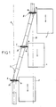
- Figure 1 recalls the principle of the transposition of elements separators 2, arranged one after the other, and connected to each other in order to constitute a continuous line.
- the row of separator elements 2 is initially positioned on a roadway along an axis A, and the operation called of transposition consists in moving laterally this line of elements separators, in a progressive manner, to position it according to another axis B, parallel to axis A.
- This transposition operation is mechanized by means of machinery 3, 4, 5 or vehicles, such as trucks or tractors, each equipped a transposition device, respectively 6, 7, 8, capable of grasping, lifting and guide the separating elements 2.
- the three machines 3, 4, 5 advancing so synchronized, one behind the other, the first gear 3 supports by his device 6 the separating elements 2 still laid along the axis A on the floor.
- the second gear 4 offset laterally with respect to the first, guides the separating elements 2 by its device 7 by imposing a start lateral deviation.
- the third gear 5, shifted even more laterally with respect to the first ensures by its device 8 a deflection additional side of the separator elements 2, and adjusts the positioning final of these separating elements 2 along axis B, on the roadway where they are finally rested.
- each element separator 2 comprises, on each side, three superimposed slides 10, 11 and 12.
- Each slide 10, 11 or 12 has a longitudinal median groove 13.
- Transposition devices such as the device 6 carried by the machine 3, are here adapted to such separator elements 2 metal, the structure of this transposition device 6 being shown in FIGS. 2 and 3.
- the transposition device 6 has two pairs superimposed of pebbles, namely an upper pair of rollers 14, and a lower pair of rollers 15, forming a symmetrical structure with respect to a median plane vertical P.
- the two superimposed rollers 14 and 15 located on the right side are worn by the same lateral support 16, and symmetrically the two rollers overlapping 14 and 15 located on the left side are carried by another support Lateral 17.
- the two rollers 14 of the upper pair are mounted rotating around respective vertical axes 18.
- the two rollers 15 of the lower pair are rotatably mounted about respective vertical axes 19.
- the provision is such that the center distance e of the two rollers 14 of the upper pair is smaller than the center distance E of the two rollers 15 of the lower pair; in other words, from each side, there is a transverse shift between the vertical axis 18 of the upper roller 14, on the one hand, and the vertical axis 19 of the lower roller 15, on the other hand.
- All rollers 14 and 15 are rotatably mounted on their respective axes 18 and 19, and are each provided with a rubber tire, or a tire inflated.
- the two lateral supports 16 and 17 are connected in a horizontally sliding at their upper part, through respective cylinders 20 and 21 of horizontal axes, to a common central support 22, located in the plane P, this arrangement allowing a spacing adjustment of the two rollers 14 of the upper pair, and a corresponding gap setting of two rollers 15 of the lower pair.
- the central support 22, which extends vertically, is itself vertically via another jack 23 of vertical axis, to a support member 24, mounted on the machine 3.
- the transposition device 6, in the position of use, is thus suspended laterally to the machine 3, as illustrated by the various figures.
- the device for transposition 6 can be brought over a separator element 2 metallic, as previously described, which still rests on the roadway C, the two lateral supports 16 and 17 being spaced apart from each other.
- Both rollers 14 of the upper pair, located at the same level, are then on both sides of the separating element 2, facing the longitudinal grooves 13 respectively of the two upper slides.
- the two pebbles 15 of the lower pair, located at the same level, are also on both sides of the separating element 2, but facing the longitudinal grooves 13 respective of the two intermediate slides 11.
- the simultaneous actuation of the two cylinders horizontals 20 and 21 makes it possible to bring the two lateral supports 16 and 17 closer together, in order to engage the rollers 14 of the upper pair in the grooves 13 upper slides, and to engage the same rollers 15 of the pair lower in the grooves 13 intermediate slides 11.
- the rollers 14 and 15 come to apply in throats 13 by their bandages in rubber.
- the separating element 2 is thus clamped between the two rollers 14 of the upper pair, and also between the two rollers 15 of the lower pair.
- the separating element 2 can be lifted, to a certain height H above the floor C, by actuating the vertical cylinder 23, as shown in Figure 3. This position tight and lifted allows the use of the transposition device 6, as illustrated in FIG. 1.
Landscapes
- Engineering & Computer Science (AREA)
- Architecture (AREA)
- Civil Engineering (AREA)
- Structural Engineering (AREA)
- Vehicle Cleaning, Maintenance, Repair, Refitting, And Outriggers (AREA)
- Road Paving Structures (AREA)
- Accessories And Tools For Shearing Machines (AREA)
- Sewage (AREA)
- Automobile Manufacture Line, Endless Track Vehicle, Trailer (AREA)
- Axle Suspensions And Sidecars For Cycles (AREA)
- Radio Relay Systems (AREA)
- Crystals, And After-Treatments Of Crystals (AREA)
- Current-Collector Devices For Electrically Propelled Vehicles (AREA)
Abstract
Description
- le nombre des paires de galets du dispositif,
- la nature des moyens de réglage de l'écartement des galets, et de levage de l'ensemble de ces galets,
- les détails des éléments séparateurs à transposer, et les adaptations du dispositif à ces éléments séparateurs,
- le type d'engin ou de véhicule sur lequel le dispositif de transposition est monté,
- la répartition des dispositifs de transposition sur les engins ou véhicules porteurs, dont le nombre peut être variable, en fonction notamment de leur longueur.
Claims (5)
- Dispositif pour la transposition latérale d'éléments de séparation temporaire pour voies de circulation routière, en particulier d'éléments séparateurs métalliques (2), alors qu'ils sont posés au sol, placés bout à bout et assemblés les uns aux autres par leurs extrémités adjacentes, le dispositif (6) étant prévu pour être monté sur un véhicule ou sur un engin roulant (3), caractérisé en ce qu'il comprend au moins une paire de galets (14, 15) d'axes sensiblement verticaux (18, 19), et situés au même niveau, des moyens (20, 21) étant prévus pour régler l'écartement (e, E) des deux galets (14, 15) de la ou chaque paire de galets, et assurer le serrage de ces galets (14, 15), et d'autres moyens (23) étant prévus pour lever ou abaisser l'ensemble des galets (14, 15), de manière à permettre le serrage, le levage et le guidage d'éléments séparateurs (2), notamment métalliques, pourvus de glissières latérales (10, 11, 12), les galets (14, 15) étant prévus pour être positionnés dans des gorges longitudinales (13) de ces glissières (10, 11, 12), de part et d'autre des éléments séparateurs (2).
- Dispositif de transposition selon la revendication 1, caractérisé en ce qu'il comprend deux paires superposées de galets (14, 15) d'axes sensiblement verticaux, prévues pour coopérer avec les gorges longitudinales (13) de deux glissières superposées (10, 11) situées de part et d'autre des éléments séparateurs.
- Dispositif de transposition selon la revendication 2, caractérisé en ce que l'entraxe (e) des deux galets (14) de la paire supérieure est inférieur à l'entraxe (E) des deux galets (15) de la paire inférieure, de sorte que, sur chaque côté, les axes respectifs (18, 19) du galet supérieur (14) et du galet inférieur (15) sont décalés dans le sens transversal, pour tenir compte du profil trapézoïdal des éléments séparateurs (2).
- Dispositif de transposition selon l'une quelconque des revendications 1 à 3, caractérisé en ce que les galets (14, 15) d'axes sensiblement verticaux (18, 19) sont munis de bandages en matière du genre caoutchouc, ou de pneumatiques gonflés, les galets (14, 15) s'appliquant par ces bandages ou pneumatiques dans les gorges longitudinales (13) des glissières (10, 11 ) des éléments séparateurs (2).
- Dispositif de transposition selon l'une quelconque des revendications 1 à 4, caractérisé en ce que les moyens prévus pour régler l'écartement des galets (14, 15), et assurer le serrage de ces galets (14, 15) dans les gorges longitudinales (13) des glissières (10, 11), sont constitués par au moins deux vérins (20, 21) d'axe sensiblement horizontal, reliant un support central commun (22) aux parties supérieures respectives de supports latéraux (16, 17) desdits galets (14, 15), tandis que les moyens prévus pour lever ou abaisser l'ensemble des galets (14, 15) sont constitués par au moins un vérin (23) d'axe sensiblement vertical, reliant le support central commun (22) à un élément porteur (24) du dispositif (6), monté sur un véhicule ou engin roulant (3).
Applications Claiming Priority (2)
| Application Number | Priority Date | Filing Date | Title |
|---|---|---|---|
| FR0307500 | 2003-06-20 | ||
| FR0307500A FR2856415B1 (fr) | 2003-06-20 | 2003-06-20 | Dispositif pour la transposition d'elements separateurs pour voies de circulation routiere |
Publications (2)
| Publication Number | Publication Date |
|---|---|
| EP1489233A1 true EP1489233A1 (fr) | 2004-12-22 |
| EP1489233B1 EP1489233B1 (fr) | 2008-10-08 |
Family
ID=33396825
Family Applications (1)
| Application Number | Title | Priority Date | Filing Date |
|---|---|---|---|
| EP04356102A Expired - Lifetime EP1489233B1 (fr) | 2003-06-20 | 2004-06-17 | Dispositif pour la transposition latérale d'éléments de séparation temporaire pour voies de circulation routière |
Country Status (6)
| Country | Link |
|---|---|
| EP (1) | EP1489233B1 (fr) |
| AT (1) | ATE410554T1 (fr) |
| DE (1) | DE602004016915D1 (fr) |
| DK (1) | DK1489233T3 (fr) |
| FR (1) | FR2856415B1 (fr) |
| PT (1) | PT1489233E (fr) |
Cited By (1)
| Publication number | Priority date | Publication date | Assignee | Title |
|---|---|---|---|---|
| EP2190774A4 (fr) * | 2007-09-06 | 2013-02-27 | Energy Absorption System | Dispositif de transfert de barrière, système et procédé d'utilisation associés |
Citations (4)
| Publication number | Priority date | Publication date | Assignee | Title |
|---|---|---|---|---|
| DE4125129C1 (en) * | 1991-07-30 | 1992-08-27 | Spig Schutzplanken-Produktions-Gesellschaft Mbh & Co Kg, 6612 Schmelz, De | Mechanism for lateral-shift or road side barrier - has support arm length movable to max. width of construction vehicle and swivelable about horizontal axis |
| FR2731723A1 (fr) * | 1995-03-14 | 1996-09-20 | Beton Securit Sobes Soc | Procede pour la pose de barrieres de separation temporaire de voies de circulation, et materiel pour sa mise en oeuvre |
| DE19707525A1 (de) * | 1997-02-25 | 1998-09-03 | Spig Schutzplanken Prod Gmbh | Verfahren zum seitlichen Umsetzen einer Fahrwegseitenbegrenzung und Vorrichtung zur Durchführung des Verfahrens |
| EP1061178A1 (fr) * | 1999-06-18 | 2000-12-20 | Colas | Dispositif d'interruption de terre-plein central |
Family Cites Families (5)
| Publication number | Priority date | Publication date | Assignee | Title |
|---|---|---|---|---|
| US4500225A (en) | 1981-02-06 | 1985-02-19 | Quicksteel Engineering Pty. Ltd. | Transferable roadway lane divider |
| FR2562575B3 (fr) | 1984-04-05 | 1986-07-18 | Tech Special Securite | Systeme de balisage de voies de circulation routiere |
| FR2678872B1 (fr) | 1991-07-11 | 1993-10-01 | Gestra Sarl | Dispositif pour realiser un deplacement lateral d'une serie d'elements de balisage de voie de circulation routiere lies les uns aux autres. |
| US5246305A (en) | 1991-11-12 | 1993-09-21 | Barrier Systems, Inc. | Conveyor and method for transferring barrier systems |
| US5885046A (en) | 1996-10-02 | 1999-03-23 | Barrier Systems, Inc. | Four-wheel, double bogey for a lane barrier positioning vehicle |
-
2003
- 2003-06-20 FR FR0307500A patent/FR2856415B1/fr not_active Expired - Fee Related
-
2004
- 2004-06-17 EP EP04356102A patent/EP1489233B1/fr not_active Expired - Lifetime
- 2004-06-17 PT PT04356102T patent/PT1489233E/pt unknown
- 2004-06-17 AT AT04356102T patent/ATE410554T1/de not_active IP Right Cessation
- 2004-06-17 DE DE602004016915T patent/DE602004016915D1/de not_active Expired - Lifetime
- 2004-06-17 DK DK04356102T patent/DK1489233T3/da active
Patent Citations (4)
| Publication number | Priority date | Publication date | Assignee | Title |
|---|---|---|---|---|
| DE4125129C1 (en) * | 1991-07-30 | 1992-08-27 | Spig Schutzplanken-Produktions-Gesellschaft Mbh & Co Kg, 6612 Schmelz, De | Mechanism for lateral-shift or road side barrier - has support arm length movable to max. width of construction vehicle and swivelable about horizontal axis |
| FR2731723A1 (fr) * | 1995-03-14 | 1996-09-20 | Beton Securit Sobes Soc | Procede pour la pose de barrieres de separation temporaire de voies de circulation, et materiel pour sa mise en oeuvre |
| DE19707525A1 (de) * | 1997-02-25 | 1998-09-03 | Spig Schutzplanken Prod Gmbh | Verfahren zum seitlichen Umsetzen einer Fahrwegseitenbegrenzung und Vorrichtung zur Durchführung des Verfahrens |
| EP1061178A1 (fr) * | 1999-06-18 | 2000-12-20 | Colas | Dispositif d'interruption de terre-plein central |
Cited By (1)
| Publication number | Priority date | Publication date | Assignee | Title |
|---|---|---|---|---|
| EP2190774A4 (fr) * | 2007-09-06 | 2013-02-27 | Energy Absorption System | Dispositif de transfert de barrière, système et procédé d'utilisation associés |
Also Published As
| Publication number | Publication date |
|---|---|
| FR2856415A1 (fr) | 2004-12-24 |
| PT1489233E (pt) | 2008-12-29 |
| EP1489233B1 (fr) | 2008-10-08 |
| DK1489233T3 (da) | 2009-02-16 |
| ATE410554T1 (de) | 2008-10-15 |
| FR2856415B1 (fr) | 2007-07-06 |
| DE602004016915D1 (de) | 2008-11-20 |
Similar Documents
| Publication | Publication Date | Title |
|---|---|---|
| EP0019984B1 (fr) | Train de renouvellement d'une voie de chemin de fer | |
| FR2476708A1 (fr) | Ensemble mobile pour le nettoyage de la couche de ballast des voies ferrees et procede de nettoyage utilisant un tel ensemble | |
| AU2015245440B2 (en) | Method for laying railway tracks | |
| FR2617744A1 (fr) | Procede et installation de planage d'une bande metallique | |
| EP1489233B1 (fr) | Dispositif pour la transposition latérale d'éléments de séparation temporaire pour voies de circulation routière | |
| EP1491306A2 (fr) | Machine pour la fabrication en continu de pièces en béton précontraintes ou armées | |
| FR2975682A1 (fr) | Train de chariots pour ripage d'alignement de blocs separateurs de voies de circulation | |
| CA1225823A (fr) | Appareil pour enlever les bavures sur un produit de coulee continue | |
| FR2731723A1 (fr) | Procede pour la pose de barrieres de separation temporaire de voies de circulation, et materiel pour sa mise en oeuvre | |
| US2845851A (en) | Machine for making anti-skid concrete road surfaces | |
| WO2002086247A1 (fr) | Equipement de voirie pret a l'installation et procede d'installation correspondant | |
| FR2689150A1 (fr) | Machine de bourrage de voie ferrée. | |
| JP5198756B2 (ja) | 施工装置 | |
| AU2012200458B2 (en) | A plough for railway roadbed ballast | |
| AT14054U1 (de) | Schleifaggregat zum Abschleifen einer Schiene | |
| FR2876993A1 (fr) | Dispositif pour positionner simultanement au moins un operateur et des elements de construction et procede de montage utilisant un tel dispositif. | |
| FR3019565A1 (fr) | Procede de realisation d'un carrefour de tramway | |
| EP1094156A1 (fr) | Procédé de confinement d'enrobés bitumineux au voisinage d'un rail et dispositif pour sa mise en oeuvre | |
| CN208118877U (zh) | 包轮式车轮防滑防陷履带 | |
| EP3168364B1 (fr) | Jeu de pièces d'ajustement entre une dalle et des voies de roulement ferroviaire ou sur pneumatiques | |
| JP3794334B2 (ja) | 路面切削機 | |
| FR2903709A1 (fr) | Materiel de protection pour la pose, la manipulation et le retrait de barrieres de separation de voies de circulation routiere. | |
| SU988957A1 (ru) | Машина дл удалени снежно-лед ных образований с дорожных покрытий | |
| FR2547514A1 (fr) | Systeme de remplacement de cages de laminoirs a profiles, chariot porte-cages multifonctions pour la mise en place sur les sites de laminage et le transport vers les sites de premontage | |
| FR2698281A1 (fr) | Système de pelouse et procédé de mise en place d'une pelouse dans un stade. |
Legal Events
| Date | Code | Title | Description |
|---|---|---|---|
| PUAI | Public reference made under article 153(3) epc to a published international application that has entered the european phase |
Free format text: ORIGINAL CODE: 0009012 |
|
| AK | Designated contracting states |
Kind code of ref document: A1 Designated state(s): AT BE BG CH CY CZ DE DK EE ES FI FR GB GR HU IE IT LI LU MC NL PL PT RO SE SI SK TR |
|
| AX | Request for extension of the european patent |
Extension state: AL HR LT LV MK |
|
| 17P | Request for examination filed |
Effective date: 20050316 |
|
| AKX | Designation fees paid |
Designated state(s): AT BE BG CH CY CZ DE DK EE ES FI FR GB GR HU IE IT LI LU MC NL PL PT RO SE SI SK TR |
|
| AXX | Extension fees paid |
Extension state: HR Payment date: 20050316 |
|
| GRAP | Despatch of communication of intention to grant a patent |
Free format text: ORIGINAL CODE: EPIDOSNIGR1 |
|
| GRAS | Grant fee paid |
Free format text: ORIGINAL CODE: EPIDOSNIGR3 |
|
| GRAA | (expected) grant |
Free format text: ORIGINAL CODE: 0009210 |
|
| AK | Designated contracting states |
Kind code of ref document: B1 Designated state(s): AT BE BG CH CY CZ DE DK EE ES FI FR GB GR HU IE IT LI LU MC NL PL PT RO SE SI SK TR |
|
| AX | Request for extension of the european patent |
Extension state: HR |
|
| REG | Reference to a national code |
Ref country code: GB Ref legal event code: FG4D Free format text: NOT ENGLISH |
|
| REG | Reference to a national code |
Ref country code: CH Ref legal event code: EP |
|
| REG | Reference to a national code |
Ref country code: IE Ref legal event code: FG4D Free format text: LANGUAGE OF EP DOCUMENT: FRENCH |
|
| REF | Corresponds to: |
Ref document number: 602004016915 Country of ref document: DE Date of ref document: 20081120 Kind code of ref document: P |
|
| REG | Reference to a national code |
Ref country code: PT Ref legal event code: SC4A Free format text: AVAILABILITY OF NATIONAL TRANSLATION Effective date: 20081216 |
|
| REG | Reference to a national code |
Ref country code: DK Ref legal event code: T3 |
|
| PG25 | Lapsed in a contracting state [announced via postgrant information from national office to epo] |
Ref country code: SI Free format text: LAPSE BECAUSE OF FAILURE TO SUBMIT A TRANSLATION OF THE DESCRIPTION OR TO PAY THE FEE WITHIN THE PRESCRIBED TIME-LIMIT Effective date: 20081008 |
|
| PG25 | Lapsed in a contracting state [announced via postgrant information from national office to epo] |
Ref country code: ES Free format text: LAPSE BECAUSE OF FAILURE TO SUBMIT A TRANSLATION OF THE DESCRIPTION OR TO PAY THE FEE WITHIN THE PRESCRIBED TIME-LIMIT Effective date: 20090119 Ref country code: AT Free format text: LAPSE BECAUSE OF FAILURE TO SUBMIT A TRANSLATION OF THE DESCRIPTION OR TO PAY THE FEE WITHIN THE PRESCRIBED TIME-LIMIT Effective date: 20081008 Ref country code: BG Free format text: LAPSE BECAUSE OF FAILURE TO SUBMIT A TRANSLATION OF THE DESCRIPTION OR TO PAY THE FEE WITHIN THE PRESCRIBED TIME-LIMIT Effective date: 20090108 |
|
| PG25 | Lapsed in a contracting state [announced via postgrant information from national office to epo] |
Ref country code: PL Free format text: LAPSE BECAUSE OF FAILURE TO SUBMIT A TRANSLATION OF THE DESCRIPTION OR TO PAY THE FEE WITHIN THE PRESCRIBED TIME-LIMIT Effective date: 20081008 |
|
| PG25 | Lapsed in a contracting state [announced via postgrant information from national office to epo] |
Ref country code: RO Free format text: LAPSE BECAUSE OF FAILURE TO SUBMIT A TRANSLATION OF THE DESCRIPTION OR TO PAY THE FEE WITHIN THE PRESCRIBED TIME-LIMIT Effective date: 20081008 Ref country code: EE Free format text: LAPSE BECAUSE OF FAILURE TO SUBMIT A TRANSLATION OF THE DESCRIPTION OR TO PAY THE FEE WITHIN THE PRESCRIBED TIME-LIMIT Effective date: 20081008 |
|
| PLBE | No opposition filed within time limit |
Free format text: ORIGINAL CODE: 0009261 |
|
| STAA | Information on the status of an ep patent application or granted ep patent |
Free format text: STATUS: NO OPPOSITION FILED WITHIN TIME LIMIT |
|
| PG25 | Lapsed in a contracting state [announced via postgrant information from national office to epo] |
Ref country code: IT Free format text: LAPSE BECAUSE OF FAILURE TO SUBMIT A TRANSLATION OF THE DESCRIPTION OR TO PAY THE FEE WITHIN THE PRESCRIBED TIME-LIMIT Effective date: 20081008 Ref country code: CZ Free format text: LAPSE BECAUSE OF FAILURE TO SUBMIT A TRANSLATION OF THE DESCRIPTION OR TO PAY THE FEE WITHIN THE PRESCRIBED TIME-LIMIT Effective date: 20081008 Ref country code: SE Free format text: LAPSE BECAUSE OF FAILURE TO SUBMIT A TRANSLATION OF THE DESCRIPTION OR TO PAY THE FEE WITHIN THE PRESCRIBED TIME-LIMIT Effective date: 20090108 |
|
| 26N | No opposition filed |
Effective date: 20090709 |
|
| PG25 | Lapsed in a contracting state [announced via postgrant information from national office to epo] |
Ref country code: SK Free format text: LAPSE BECAUSE OF FAILURE TO SUBMIT A TRANSLATION OF THE DESCRIPTION OR TO PAY THE FEE WITHIN THE PRESCRIBED TIME-LIMIT Effective date: 20081008 |
|
| PG25 | Lapsed in a contracting state [announced via postgrant information from national office to epo] |
Ref country code: MC Free format text: LAPSE BECAUSE OF NON-PAYMENT OF DUE FEES Effective date: 20090630 |
|
| REG | Reference to a national code |
Ref country code: CH Ref legal event code: PL |
|
| PG25 | Lapsed in a contracting state [announced via postgrant information from national office to epo] |
Ref country code: CH Free format text: LAPSE BECAUSE OF NON-PAYMENT OF DUE FEES Effective date: 20090630 Ref country code: LI Free format text: LAPSE BECAUSE OF NON-PAYMENT OF DUE FEES Effective date: 20090630 |
|
| PG25 | Lapsed in a contracting state [announced via postgrant information from national office to epo] |
Ref country code: GR Free format text: LAPSE BECAUSE OF FAILURE TO SUBMIT A TRANSLATION OF THE DESCRIPTION OR TO PAY THE FEE WITHIN THE PRESCRIBED TIME-LIMIT Effective date: 20090109 |
|
| PG25 | Lapsed in a contracting state [announced via postgrant information from national office to epo] |
Ref country code: HU Free format text: LAPSE BECAUSE OF FAILURE TO SUBMIT A TRANSLATION OF THE DESCRIPTION OR TO PAY THE FEE WITHIN THE PRESCRIBED TIME-LIMIT Effective date: 20090409 |
|
| PG25 | Lapsed in a contracting state [announced via postgrant information from national office to epo] |
Ref country code: TR Free format text: LAPSE BECAUSE OF FAILURE TO SUBMIT A TRANSLATION OF THE DESCRIPTION OR TO PAY THE FEE WITHIN THE PRESCRIBED TIME-LIMIT Effective date: 20081008 |
|
| PG25 | Lapsed in a contracting state [announced via postgrant information from national office to epo] |
Ref country code: CY Free format text: LAPSE BECAUSE OF FAILURE TO SUBMIT A TRANSLATION OF THE DESCRIPTION OR TO PAY THE FEE WITHIN THE PRESCRIBED TIME-LIMIT Effective date: 20081008 |
|
| REG | Reference to a national code |
Ref country code: FR Ref legal event code: PLFP Year of fee payment: 13 |
|
| REG | Reference to a national code |
Ref country code: FR Ref legal event code: PLFP Year of fee payment: 14 |
|
| REG | Reference to a national code |
Ref country code: FR Ref legal event code: PLFP Year of fee payment: 15 |
|
| PGFP | Annual fee paid to national office [announced via postgrant information from national office to epo] |
Ref country code: DE Payment date: 20200515 Year of fee payment: 17 Ref country code: FI Payment date: 20200518 Year of fee payment: 17 Ref country code: LU Payment date: 20200515 Year of fee payment: 17 Ref country code: DK Payment date: 20200526 Year of fee payment: 17 Ref country code: IE Payment date: 20200522 Year of fee payment: 17 Ref country code: PT Payment date: 20200518 Year of fee payment: 17 Ref country code: FR Payment date: 20200514 Year of fee payment: 17 Ref country code: NL Payment date: 20200515 Year of fee payment: 17 |
|
| PGFP | Annual fee paid to national office [announced via postgrant information from national office to epo] |
Ref country code: GB Payment date: 20200514 Year of fee payment: 17 Ref country code: BE Payment date: 20200616 Year of fee payment: 17 |
|
| REG | Reference to a national code |
Ref country code: DE Ref legal event code: R119 Ref document number: 602004016915 Country of ref document: DE |
|
| REG | Reference to a national code |
Ref country code: FI Ref legal event code: MAE |
|
| REG | Reference to a national code |
Ref country code: DK Ref legal event code: EBP Effective date: 20210630 |
|
| PG25 | Lapsed in a contracting state [announced via postgrant information from national office to epo] |
Ref country code: PT Free format text: LAPSE BECAUSE OF NON-PAYMENT OF DUE FEES Effective date: 20211217 Ref country code: FI Free format text: LAPSE BECAUSE OF NON-PAYMENT OF DUE FEES Effective date: 20210617 |
|
| REG | Reference to a national code |
Ref country code: NL Ref legal event code: MM Effective date: 20210701 |
|
| GBPC | Gb: european patent ceased through non-payment of renewal fee |
Effective date: 20210617 |
|
| REG | Reference to a national code |
Ref country code: BE Ref legal event code: MM Effective date: 20210630 |
|
| PG25 | Lapsed in a contracting state [announced via postgrant information from national office to epo] |
Ref country code: LU Free format text: LAPSE BECAUSE OF NON-PAYMENT OF DUE FEES Effective date: 20210617 |
|
| PG25 | Lapsed in a contracting state [announced via postgrant information from national office to epo] |
Ref country code: IE Free format text: LAPSE BECAUSE OF NON-PAYMENT OF DUE FEES Effective date: 20210617 Ref country code: GB Free format text: LAPSE BECAUSE OF NON-PAYMENT OF DUE FEES Effective date: 20210617 Ref country code: DE Free format text: LAPSE BECAUSE OF NON-PAYMENT OF DUE FEES Effective date: 20220101 |
|
| PG25 | Lapsed in a contracting state [announced via postgrant information from national office to epo] |
Ref country code: NL Free format text: LAPSE BECAUSE OF NON-PAYMENT OF DUE FEES Effective date: 20210701 Ref country code: FR Free format text: LAPSE BECAUSE OF NON-PAYMENT OF DUE FEES Effective date: 20210630 |
|
| PG25 | Lapsed in a contracting state [announced via postgrant information from national office to epo] |
Ref country code: DK Free format text: LAPSE BECAUSE OF NON-PAYMENT OF DUE FEES Effective date: 20210630 Ref country code: BE Free format text: LAPSE BECAUSE OF NON-PAYMENT OF DUE FEES Effective date: 20210630 |