EP1487575B2 - Verfahren zur herstellung eines vanadium, phosphor und sauerstoff enthaltenden katalysators - Google Patents
Verfahren zur herstellung eines vanadium, phosphor und sauerstoff enthaltenden katalysators Download PDFInfo
- Publication number
- EP1487575B2 EP1487575B2 EP03708212A EP03708212A EP1487575B2 EP 1487575 B2 EP1487575 B2 EP 1487575B2 EP 03708212 A EP03708212 A EP 03708212A EP 03708212 A EP03708212 A EP 03708212A EP 1487575 B2 EP1487575 B2 EP 1487575B2
- Authority
- EP
- European Patent Office
- Prior art keywords
- gas
- catalyst precursor
- catalyst
- calcining
- calcination
- Prior art date
- Legal status (The legal status is an assumption and is not a legal conclusion. Google has not performed a legal analysis and makes no representation as to the accuracy of the status listed.)
- Expired - Lifetime
Links
Images

Classifications
-
- B—PERFORMING OPERATIONS; TRANSPORTING
- B01—PHYSICAL OR CHEMICAL PROCESSES OR APPARATUS IN GENERAL
- B01J—CHEMICAL OR PHYSICAL PROCESSES, e.g. CATALYSIS OR COLLOID CHEMISTRY; THEIR RELEVANT APPARATUS
- B01J8/00—Chemical or physical processes in general, conducted in the presence of fluids and solid particles; Apparatus for such processes
- B01J8/08—Chemical or physical processes in general, conducted in the presence of fluids and solid particles; Apparatus for such processes with moving particles
- B01J8/10—Chemical or physical processes in general, conducted in the presence of fluids and solid particles; Apparatus for such processes with moving particles moved by stirrers or by rotary drums or rotary receptacles or endless belts
-
- B—PERFORMING OPERATIONS; TRANSPORTING
- B01—PHYSICAL OR CHEMICAL PROCESSES OR APPARATUS IN GENERAL
- B01J—CHEMICAL OR PHYSICAL PROCESSES, e.g. CATALYSIS OR COLLOID CHEMISTRY; THEIR RELEVANT APPARATUS
- B01J19/00—Chemical, physical or physico-chemical processes in general; Their relevant apparatus
- B01J19/18—Stationary reactors having moving elements inside
- B01J19/22—Stationary reactors having moving elements inside in the form of endless belts
-
- B—PERFORMING OPERATIONS; TRANSPORTING
- B01—PHYSICAL OR CHEMICAL PROCESSES OR APPARATUS IN GENERAL
- B01J—CHEMICAL OR PHYSICAL PROCESSES, e.g. CATALYSIS OR COLLOID CHEMISTRY; THEIR RELEVANT APPARATUS
- B01J27/00—Catalysts comprising the elements or compounds of halogens, sulfur, selenium, tellurium, phosphorus or nitrogen; Catalysts comprising carbon compounds
- B01J27/14—Phosphorus; Compounds thereof
- B01J27/186—Phosphorus; Compounds thereof with arsenic, antimony, bismuth, vanadium, niobium, tantalum, polonium, chromium, molybdenum, tungsten, manganese, technetium or rhenium
- B01J27/195—Phosphorus; Compounds thereof with arsenic, antimony, bismuth, vanadium, niobium, tantalum, polonium, chromium, molybdenum, tungsten, manganese, technetium or rhenium with vanadium, niobium or tantalum
- B01J27/198—Vanadium
-
- B—PERFORMING OPERATIONS; TRANSPORTING
- B01—PHYSICAL OR CHEMICAL PROCESSES OR APPARATUS IN GENERAL
- B01J—CHEMICAL OR PHYSICAL PROCESSES, e.g. CATALYSIS OR COLLOID CHEMISTRY; THEIR RELEVANT APPARATUS
- B01J35/00—Catalysts, in general, characterised by their form or physical properties
- B01J35/30—Catalysts, in general, characterised by their form or physical properties characterised by their physical properties
- B01J35/34—Mechanical properties
- B01J35/37—Crush or impact strength
-
- B—PERFORMING OPERATIONS; TRANSPORTING
- B01—PHYSICAL OR CHEMICAL PROCESSES OR APPARATUS IN GENERAL
- B01J—CHEMICAL OR PHYSICAL PROCESSES, e.g. CATALYSIS OR COLLOID CHEMISTRY; THEIR RELEVANT APPARATUS
- B01J35/00—Catalysts, in general, characterised by their form or physical properties
- B01J35/30—Catalysts, in general, characterised by their form or physical properties characterised by their physical properties
- B01J35/34—Mechanical properties
- B01J35/38—Abrasion or attrition resistance
-
- B—PERFORMING OPERATIONS; TRANSPORTING
- B01—PHYSICAL OR CHEMICAL PROCESSES OR APPARATUS IN GENERAL
- B01J—CHEMICAL OR PHYSICAL PROCESSES, e.g. CATALYSIS OR COLLOID CHEMISTRY; THEIR RELEVANT APPARATUS
- B01J35/00—Catalysts, in general, characterised by their form or physical properties
- B01J35/40—Catalysts, in general, characterised by their form or physical properties characterised by dimensions, e.g. grain size
-
- B—PERFORMING OPERATIONS; TRANSPORTING
- B01—PHYSICAL OR CHEMICAL PROCESSES OR APPARATUS IN GENERAL
- B01J—CHEMICAL OR PHYSICAL PROCESSES, e.g. CATALYSIS OR COLLOID CHEMISTRY; THEIR RELEVANT APPARATUS
- B01J35/00—Catalysts, in general, characterised by their form or physical properties
- B01J35/50—Catalysts, in general, characterised by their form or physical properties characterised by their shape or configuration
- B01J35/55—Cylinders or rings
-
- B—PERFORMING OPERATIONS; TRANSPORTING
- B01—PHYSICAL OR CHEMICAL PROCESSES OR APPARATUS IN GENERAL
- B01J—CHEMICAL OR PHYSICAL PROCESSES, e.g. CATALYSIS OR COLLOID CHEMISTRY; THEIR RELEVANT APPARATUS
- B01J37/00—Processes, in general, for preparing catalysts; Processes, in general, for activation of catalysts
- B01J37/08—Heat treatment
-
- B—PERFORMING OPERATIONS; TRANSPORTING
- B01—PHYSICAL OR CHEMICAL PROCESSES OR APPARATUS IN GENERAL
- B01J—CHEMICAL OR PHYSICAL PROCESSES, e.g. CATALYSIS OR COLLOID CHEMISTRY; THEIR RELEVANT APPARATUS
- B01J8/00—Chemical or physical processes in general, conducted in the presence of fluids and solid particles; Apparatus for such processes
- B01J8/02—Chemical or physical processes in general, conducted in the presence of fluids and solid particles; Apparatus for such processes with stationary particles, e.g. in fixed beds
- B01J8/06—Chemical or physical processes in general, conducted in the presence of fluids and solid particles; Apparatus for such processes with stationary particles, e.g. in fixed beds in tube reactors; the solid particles being arranged in tubes
- B01J8/067—Heating or cooling the reactor
-
- C—CHEMISTRY; METALLURGY
- C07—ORGANIC CHEMISTRY
- C07C—ACYCLIC OR CARBOCYCLIC COMPOUNDS
- C07C51/00—Preparation of carboxylic acids or their salts, halides or anhydrides
- C07C51/16—Preparation of carboxylic acids or their salts, halides or anhydrides by oxidation
- C07C51/21—Preparation of carboxylic acids or their salts, halides or anhydrides by oxidation with molecular oxygen
- C07C51/215—Preparation of carboxylic acids or their salts, halides or anhydrides by oxidation with molecular oxygen of saturated hydrocarbyl groups
-
- C—CHEMISTRY; METALLURGY
- C07—ORGANIC CHEMISTRY
- C07C—ACYCLIC OR CARBOCYCLIC COMPOUNDS
- C07C51/00—Preparation of carboxylic acids or their salts, halides or anhydrides
- C07C51/16—Preparation of carboxylic acids or their salts, halides or anhydrides by oxidation
- C07C51/21—Preparation of carboxylic acids or their salts, halides or anhydrides by oxidation with molecular oxygen
- C07C51/25—Preparation of carboxylic acids or their salts, halides or anhydrides by oxidation with molecular oxygen of unsaturated compounds containing no six-membered aromatic ring
- C07C51/252—Preparation of carboxylic acids or their salts, halides or anhydrides by oxidation with molecular oxygen of unsaturated compounds containing no six-membered aromatic ring of propene, butenes, acrolein or methacrolein
-
- C—CHEMISTRY; METALLURGY
- C07—ORGANIC CHEMISTRY
- C07C—ACYCLIC OR CARBOCYCLIC COMPOUNDS
- C07C57/00—Unsaturated compounds having carboxyl groups bound to acyclic carbon atoms
- C07C57/02—Unsaturated compounds having carboxyl groups bound to acyclic carbon atoms with only carbon-to-carbon double bonds as unsaturation
- C07C57/13—Dicarboxylic acids
- C07C57/145—Maleic acid
-
- B—PERFORMING OPERATIONS; TRANSPORTING
- B01—PHYSICAL OR CHEMICAL PROCESSES OR APPARATUS IN GENERAL
- B01J—CHEMICAL OR PHYSICAL PROCESSES, e.g. CATALYSIS OR COLLOID CHEMISTRY; THEIR RELEVANT APPARATUS
- B01J2208/00—Processes carried out in the presence of solid particles; Reactors therefor
- B01J2208/00796—Details of the reactor or of the particulate material
- B01J2208/00823—Mixing elements
- B01J2208/00831—Stationary elements
- B01J2208/00849—Stationary elements outside the bed, e.g. baffles
-
- B—PERFORMING OPERATIONS; TRANSPORTING
- B01—PHYSICAL OR CHEMICAL PROCESSES OR APPARATUS IN GENERAL
- B01J—CHEMICAL OR PHYSICAL PROCESSES, e.g. CATALYSIS OR COLLOID CHEMISTRY; THEIR RELEVANT APPARATUS
- B01J2208/00—Processes carried out in the presence of solid particles; Reactors therefor
- B01J2208/00796—Details of the reactor or of the particulate material
- B01J2208/00823—Mixing elements
- B01J2208/00858—Moving elements
- B01J2208/00876—Moving elements outside the bed, e.g. rotary mixer
-
- B—PERFORMING OPERATIONS; TRANSPORTING
- B01—PHYSICAL OR CHEMICAL PROCESSES OR APPARATUS IN GENERAL
- B01J—CHEMICAL OR PHYSICAL PROCESSES, e.g. CATALYSIS OR COLLOID CHEMISTRY; THEIR RELEVANT APPARATUS
- B01J2219/00—Chemical, physical or physico-chemical processes in general; Their relevant apparatus
- B01J2219/18—Details relating to the spatial orientation of the reactor
- B01J2219/182—Details relating to the spatial orientation of the reactor horizontal
-
- B—PERFORMING OPERATIONS; TRANSPORTING
- B01—PHYSICAL OR CHEMICAL PROCESSES OR APPARATUS IN GENERAL
- B01J—CHEMICAL OR PHYSICAL PROCESSES, e.g. CATALYSIS OR COLLOID CHEMISTRY; THEIR RELEVANT APPARATUS
- B01J35/00—Catalysts, in general, characterised by their form or physical properties
- B01J35/60—Catalysts, in general, characterised by their form or physical properties characterised by their surface properties or porosity
- B01J35/61—Surface area
- B01J35/613—10-100 m2/g
-
- B—PERFORMING OPERATIONS; TRANSPORTING
- B01—PHYSICAL OR CHEMICAL PROCESSES OR APPARATUS IN GENERAL
- B01J—CHEMICAL OR PHYSICAL PROCESSES, e.g. CATALYSIS OR COLLOID CHEMISTRY; THEIR RELEVANT APPARATUS
- B01J35/00—Catalysts, in general, characterised by their form or physical properties
- B01J35/60—Catalysts, in general, characterised by their form or physical properties characterised by their surface properties or porosity
- B01J35/63—Pore volume
- B01J35/633—Pore volume less than 0.5 ml/g
-
- B—PERFORMING OPERATIONS; TRANSPORTING
- B01—PHYSICAL OR CHEMICAL PROCESSES OR APPARATUS IN GENERAL
- B01J—CHEMICAL OR PHYSICAL PROCESSES, e.g. CATALYSIS OR COLLOID CHEMISTRY; THEIR RELEVANT APPARATUS
- B01J37/00—Processes, in general, for preparing catalysts; Processes, in general, for activation of catalysts
- B01J37/0009—Use of binding agents; Moulding; Pressing; Powdering; Granulating; Addition of materials ameliorating the mechanical properties of the product catalyst
-
- B—PERFORMING OPERATIONS; TRANSPORTING
- B01—PHYSICAL OR CHEMICAL PROCESSES OR APPARATUS IN GENERAL
- B01J—CHEMICAL OR PHYSICAL PROCESSES, e.g. CATALYSIS OR COLLOID CHEMISTRY; THEIR RELEVANT APPARATUS
- B01J37/00—Processes, in general, for preparing catalysts; Processes, in general, for activation of catalysts
- B01J37/12—Oxidising
- B01J37/14—Oxidising with gases containing free oxygen
-
- B—PERFORMING OPERATIONS; TRANSPORTING
- B01—PHYSICAL OR CHEMICAL PROCESSES OR APPARATUS IN GENERAL
- B01J—CHEMICAL OR PHYSICAL PROCESSES, e.g. CATALYSIS OR COLLOID CHEMISTRY; THEIR RELEVANT APPARATUS
- B01J37/00—Processes, in general, for preparing catalysts; Processes, in general, for activation of catalysts
- B01J37/16—Reducing
- B01J37/18—Reducing with gases containing free hydrogen
Definitions
- the present invention relates to a process for the preparation of a catalyst containing vanadium, phosphorus and oxygen suitable for the heterogeneous catalytic gas phase oxidation of a hydrocarbon having at least four carbon atoms to maleic anhydride, which comprises a corresponding vanadium, phosphorus and oxygen containing catalyst precursor, which particles having an average diameter of at least 2 mm, converted by calcination in a catalytically active form.
- Maleic anhydride is an important intermediate in the synthesis of ⁇ -butyrolactone, tetrahydrofuran and 1,4-butanediol, which in turn are used as solvents or further processed, for example, to polymers such as polytetrahydrofuran or polyvinylpyrrolidone.
- VPO catalysts vanadium-, phosphorus- and oxygen-containing catalysts
- the reaction is usually carried out in a salt bath-cooled fixed bed tubular reactor. Depending on the size of the plant this has a few thousand to tens of thousands, filled with catalyst tubes.
- the heat of reaction formed is transferred and removed via the wall of the catalyst-filled tubes to the surrounding salt bath, usually a eutectic mixture of potassium and sodium nitrate.
- salt bath cooling no uniform temperature arises over the length and cross section of the catalyst-filled tubes. It comes to the formation of overheated areas, so-called hot spots ("hot spots").
- hot spots hot spots
- the hydrocarbon concentration of the reaction mixture is highest near the entry point of the catalyst-filled tubes and lowest at the exit site, resulting in the formation of said overheated areas near the entry site.
- overheated areas in the catalyst-filled tubes is disadvantageous for several reasons. In the superheated areas, excessive oxidation beyond the desired oxidation level occurs. In addition, excessive thermal stress affects catalyst performance and life. As the reaction temperature increases with increasing temperature and thus more heat is produced, the formation of overheated areas can eventually lead to an uncontrolled course of the reaction, which can lead to an explosive runaway reaction.
- the tube bundle reactor will operate in such a way that the reaction temperature to ensure an economically attractive yield is as high as possible, but the overheated areas in the individual tubes do not lead to an uncontrolled reaction course.
- the temperatures occurring in the individual tubes are not exactly the same.
- Crucial for the operation of the entire tube bundle reactor is ultimately the reaction temperature of the hottest tube. The stronger the scattering of the resulting temperatures, the lower the average reaction temperature for safety reasons set. Low scattering is therefore desirable.
- care is taken to ensure that the same amount of catalyst or the same catalyst mixture is present in all tubes. It is also customary to perform a so-called pressure balance after filling the tubes with the catalyst and to adjust the same flow resistance by adding further inert material in all tubes. This measure ensures that during operation all tubes are flowed through with the same amount of gas.
- US 4,567,158 discloses the calcination of the formed vanadyl phosphate hemihydrate precursor tablets in a forced air oven, wherein one and two stage calcinations are described.
- the precursor pellets are air-treated at 350 ° C.
- the precursor pellets are first calcined under air at 350 to 400 ° C and then under a nitrogen / steam atmosphere at 330 to 500 ° C.
- US 5,137,860 teaches the calcination of the shaped vanadyl phosphate hemihydrate precursor pellets on perforated stainless steel sheets in a tray furnace.
- the precursor tablets are first treated in an oxygen, water vapor and optionally inert gas-containing atmosphere at a temperature up to 300 ° C, then subjected to a temperature increase to greater than 350 ° C and less than 550 ° C for adjusting the vanadium oxidation state and Subsequently, the temperature treatment under a non-oxidizing, water vapor-containing atmosphere with a water content of 25 to 75 mol% continued.
- US 4,996,179 teaches preforming a vanadium, phosphorus, and oxygen-containing catalyst precursor powder obtained by precipitation, evaporation, and drying in air or a nitrogen-air mixture at 300 to 370 ° C in a rotary tube or fluidized bed furnace.
- the preformed catalyst precursor powder obtained is then tableted and calcined in an inert atmosphere at a temperature of 343 to 704 ° C and then in an oxygen-containing atmosphere at elevated temperature.
- US 5,530,144 teaches the calcination of vanadyl phosphate hemihydrate precursors under nitrogen, air or mixtures thereof at a temperature of 350 to 700 ° C in a suitable calciner.
- a suitable calciner As general examples are called fluidized bed furnace, rotary kiln and continuously operated muffle furnace.
- calcination generally means thermal treatment steps, including evaporation or decomposition of components contained in the catalyst precursor, such as the drying or decomposition of an adjuvant.
- a so-called belt calcination apparatus with at least one calcination zone n and a conveyor belt guided through the calcining zone at a substantially constant speed is used to carry out the process according to the invention.
- the conveyor belt is typically an endless belt which is horizontally passable through the calcining zone and has at one end an ascending reverse path and at the other end a descending reversed path.
- means for applying the particulate catalyst precursor to the conveyor belt and at the descending reverse path means for removing the calcined catalyst from the conveyor belt are provided in the vicinity of the rising reversal path.
- a suitable means for applying for example, to call a filled with the particulate catalyst precursor shaft, wherein a bed of Katalysatorprecursors with a substantially constant layer thickness is pulled away under the shaft by the movement of the conveyor belt.
- the well also has an adjustable stripping device, i. a so-called weir, which allows a targeted adjustment of the layer height and a uniform distribution transverse to the conveying direction.
- the bed height of the Katalysatorprecursors can be chosen almost arbitrary, while ensuring a sufficient gas exchange and the desired temperature stability in principle. In general, it is in the range of one monolayer of the catalyst precursor particles up to 25 cm, preferably 1 to 20 cm, more preferably 5 to 15 cm and most preferably 8 to 15 cm.
- the calcined catalyst is discarded from the conveyor and collected by suitable means.
- the conveyor belt is usually made of a heat-resistant material, such as metal.
- the speed at which the conveyor belt passes through the calcining zone n is generally about 0.1 to 5 cm / min.
- the speed of the conveyor belt and thus of the current of the catalyst precursor is essentially constant in the method according to the invention, the time scale to be considered lying in the order of magnitude of the residence time of the flow of the catalyst precursor in the chamber n.
- a gas-permeable conveyor belt is used and, in the calcining zone n, conducts a gas flow through the flow of the catalyst precursor perpendicular to the direction of travel.
- the gas-permeable conveyor belt consists for example of a perforated band, a woven fabric or a knitted fabric of heat-resistant material, for example of metal, such as alloy steel.
- the calcination zone n is generally formed in the form of a so-called chamber, i. surrounded by lateral walls and an upper and a lower wall.
- the walls located in the conveying direction of the conveyor belt are provided with openings for carrying out the flow of the catalyst precursor.
- the heating of the chamber can be done in various ways. For example, it is possible to supply the required heat via the supply of heated gas, e.g. previously removed from the chamber and heated by a heating source to bring. Furthermore, it is possible to heat the chamber n via the walls, for example electrically or via burners. Preferably, the heating is effected by a burner located below the chamber, which is operated approximately with natural gas. In order to achieve a uniform distribution of heat, the so-called combustion chamber is surrounded by another wall and insulated to the outside. In general, the temperature in the calcination zone n is measured via temperature measuring points (for example thermocouples) and the heating is regulated accordingly.
- temperature measuring points for example thermocouples
- the surrounding gas atmosphere in general has a decisive influence on the properties of the calcined catalyst and can be consumed by the calcination of gas from the surrounding atmosphere as well as resulting gaseous components can be discharged to the surrounding atmosphere, it is particularly important to the gas atmosphere by continuous Supply of fresh gas and associated with it by continuous removal of a so-called purge stream to set targeted. Depending on the desired gas atmosphere, therefore, a corresponding amount of the required fresh gas is continuously supplied and a corresponding purge stream is continuously removed.
- the atmosphere in the chamber of the calcination zone n is preferably circulated.
- the said gas circulation can be ensured in various ways.
- the chamber itself has means for generating the gas circulation.
- the means for generating the gas circulation comprise a fan suitably located above the conveyor belt in the chamber.
- the means for generating the gas circulation further comprise gas conducting means for directing the gas circulation within the chamber, the gas guiding means within the chamber each extending at the edge of the conveyor belt substantially in a plane perpendicular to the support surface of the conveyor belt.
- the means for generating the gas circulation and / or the Gasleit bootsen are advantageously designed so that the gas rises through the gas-permeable conveyor belt and the charge thereon bed of the particulate Katalysatorprecursors and descends on the walls of the chamber again.
- a gas circulation in the opposite direction is conceivable. If the band calcining device has at least two heatable chambers, these are preferably delimited from one another such that essentially no gas exchange takes place between the chambers.
- the time variation of the gas temperature from the nominal value is at any point in the region of the stream of the catalyst precursor after half the length of the calcining zone, l n / 2, respectively ⁇ 5 ° C and the local difference in gas temperature between any point in the region of the stream of the catalyst precursor after half the length of the calcining zone, l n / 2, respectively ⁇ 5 ° C.
- the temperature constancy can be checked by means of temperature measuring points, ie preferably thermocouples.
- Pro calcining zone n are preferably at least 4, more preferably at least 6 and most preferably to employ at least 10 temperature measurement points, in the region of the stream of the catalyst precursor after half the length of the calcining zone, l n / 2 equidistant as possible from each other and distributed over the entire width of the stream of Katalysatorprecursors are arranged.
- the time variation of the gas temperature from the target value is the amount of the difference between the hourly average measured at a fixed location x in the region of the catalyst precursor flow after half the length of the calcining zone l n / 2 and the desired value.
- the temporal variation of the gas temperature from the setpoint can therefore be expressed as T (hourly mean at location x) - T (setpoint)
- the local difference of the gas temperature can therefore be expressed as
- the temporal fluctuation of the gas temperature from the desired value at each point in the region of the stream of the catalyst precursor to half the length of the calcination zone I n / 2 is preferably in each case ⁇ 3 ° C. and particularly preferably in each case ⁇ 2 ° C.
- the local difference of the gas temperature between any points in the region of the stream of Katalysatorprecursors after half the length of the calcination zone l n / 2 is preferably ⁇ 3 ° C and particularly preferably each ⁇ 2 ° C.
- thermocouples The recording of the measured temperatures at the individual thermocouples and the formation of the average values are advantageously carried out automatically by a correspondingly programmed computer. By this advantageously also the control or control of the heating of the calcination zones. It is advisable to periodically calibrate the thermocouples to ensure that the maximum deviation of the measured temperature from the actual temperature is preferably less than 0.5 ° C.
- the gas atmosphere in the calcination zone n generally contains oxygen, nitrogen, hydrogen oxide (water vapor), carbon dioxide, carbon monoxide and / or noble gases. Furthermore, the gas atmosphere may also contain evaporation and decomposition products of components contained in the catalyst precursor, such as, for example, pore formers or auxiliaries.
- the stream of the catalyst precursor is subjected to calcination by at least two, for example two to ten calcining zones, the temperatures and the gas atmospheres of the individual calcining zones being able to be controlled independently of one another.
- the successive calcination zones may be thermostated to gradually increasing or decreasing temperatures.
- the individual calcination zones can also have different spatial extent, so that at constant rate of flow of the particulate catalyst precursor different residence times result in the individual calcination zones.
- the catalyst precursor may optionally be collected and intermediately stored after passing through a belt calciner and before passing through another belt calciner.
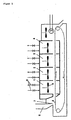
- FIG. 1 shows a longitudinal section
- Fig. 2 a cross section through the preferred Bandkalziniervorraum.
- the belt calcining apparatus shown has four chambered calcining zones (1, 2, 3, 4) through which a gas permeable conveyor belt (5) passes.
- the belt calcining device further comprises a bunker (6) with an adjustable weir (7).
- Above the conveyor belt (5) are located in each chamber one or more fan (s) (8).
- Each chamber is provided with supply and exhaust air devices (9).
- the bunker (6) is filled with the particulate catalyst precursor.
- a layer of the catalyst precursor with a constant bed height is pulled away below the weir (7) and successively passes through the chambers of the belt calcining device.
- each chamber is heated by one or more burners (9).
- gas guide plates (10) are arranged substantially in a plane perpendicular to the support surface of the conveyor belt, which together with the fans (8) ensure that the circulated atmosphere in each chamber through the gas-permeable conveyor belt (5) rises and on descends the walls of the chamber again.
- the catalyst precursors which can be used in the process according to the invention comprise, as the catalytically active compound, an oxygen-containing vanadium-phosphorus compound or mixtures of such compounds.
- Suitable active compounds are for example in the Patents US 5,275,996 . US 5,641,722 . US 5,137,860 . US 5,095,125 or US 4,933,312 described.
- Suitable promoters are the elements of groups 1 to 15 of the periodic table and their compounds. Suitable promoters are for example in the Publication WO 97/12674 and WO 95/26817 as well as in the Patents US 5,137,860 . US 5,296,436 . US 5,158,923 and US 4,795,818 described.
- Preferred promoters are compounds of the elements cobaldium, molybdenum, iron, zinc, hafnium, zirconium, lithium, titanium, chromium, manganese, nickel, copper; Boron, silicon, antimony, tin, niobium and bismuth, more preferably molybdenum, iron, zinc, antimony, bismuth, lithium.
- the promoted catalysts may contain one or more promoters. The content of promoters in total in the finished catalyst is generally not more than about 5 wt .-%, each calculated as oxide.
- the catalyst precursor may also contain so-called auxiliary agents such as tableting aids or pore formers.
- Tabletting aids are generally added when the shaping of the catalysts according to the invention is carried out by tableting.
- Tabletting aids are generally catalytically inert and improve the tabletting properties of the so-called precursor powder, an intermediate in catalyst preparation, for example by increasing the lubricity and flowability.
- As a suitable and preferred Tablettierangesstoff is called graphite.
- the added tabletting aids usually remain in the activated catalyst.
- the content of tabletting aids in the finished catalyst is about 2 to 6 wt .-%.
- Pore formers are substances which are used for the targeted adjustment of the pore structure in the macroporous area. In principle, they can be used independently of the shaping process. In general, it is carbon, hydrogen, oxygen and / or nitrogen-containing compounds which are added before shaping the catalyst and are removed in the subsequent activation of the catalyst under sublimation, decomposition and / or evaporation for the most part again. The finished catalyst may nevertheless contain residues or decomposition products of the pore-forming agent.
- the catalyst precursors which can be used in the process according to the invention can contain the active composition, for example, in pure, undiluted form as a so-called “full catalyst precursor” or diluted with a preferably oxidic support material as a so-called “mixed catalyst precursor".
- suitable carrier materials for mixed catalysts are aluminum oxide, silicon dioxide, aluminosilicates, zirconium dioxide, titanium dioxide or mixtures thereof. Preference is given to the preparation of full and mixed catalysts, particularly preferably of unsupported catalysts.
- the catalyst precursor which can be used in the process according to the invention has particles with an average diameter of at least 2 mm, preferably at least 3 mm. Below the averaged diameter of a Particles mean the mean of the smallest and the largest dimension between two plane-parallel plates.
- Particles are both irregularly shaped particles and geometrically shaped particles, so-called shaped bodies.
- the catalyst precursor to be used in the process according to the invention preferably has shaped bodies.
- suitable shaped bodies are tablets, cylinders, hollow cylinders, spheres, strands, carriage wheels or extrudates.
- Special forms, such as "Trilobes” and “Tristars” (see EP-A-0 593 646 ) or molded body with at least one notch on the outside (see US 5,168,090 ) are also possible.
- the catalyst precursor which can be used in the process according to the invention particularly preferably has shaped bodies with a substantially hollow cylindrical structure.
- a substantially hollow cylindrical structure is a structure to understand, which essentially comprises a cylinder with an opening passing between the two cover surfaces opening.
- the cylinder is characterized by two substantially parallel lid surfaces and a lateral surface, the cross-section of the cylinder, i. parallel to the top surfaces, substantially of circular structure.
- the cross-section of the through-going aperture, i. parallel to the top surfaces of the cylinder is also substantially circular in structure.
- the opening therethrough is located centrally to the lid surfaces, whereby other spatial arrangements are not excluded.
- substantially indicates that deviations from the ideal geometry, such as slight deformations of the circular structure, non-plane parallel Dekkel lake, chipped corners and edges, surface roughness or indentations in the outer surface, the cover surfaces or the inner surface of the hole therethrough Catalyst precursors are included.
- circular lid surfaces, a circular cross-section of the bore therethrough, parallel-aligned lid surfaces, and macroscopically smooth surfaces are preferred.
- the substantially hollow cylindrical structure can be described by an outer diameter d 1 , a height h as the distance between the two cover surfaces and a diameter of the inner hole (through opening) d 2 .
- the outer diameter d 1 of the catalyst precursor is preferably 3 to 10 mm, particularly preferably 4 to 8 mm, very particularly preferably 4.5 to 6 mm.
- the height h is preferably 1 to 10 mm, more preferably 2 to 6 mm, most preferably 2 to 3.5 mm.
- the diameter of the opening d 2 is preferably 1 to 8 mm, more preferably 2 to 6 mm, most preferably 2 to 3 mm.
- the calcination of the catalyst precursor takes place in the process according to the invention in the presence of a Atmosphere containing oxygen, hydrogen oxide (water vapor) and / or inert gas in a temperature range of 250 to 600 ° C.
- suitable inert gases are nitrogen, carbon dioxide and noble gases.
- at least two calcining zones are preferably passed through with different gas atmospheres and possibly different temperatures.
- the catalyst precursor is preferably used in an oxidizing atmosphere containing from 2 to 21% by volume, and preferably from 5 to 21% by volume, of molecular oxygen at a temperature of 200 to 350 ° C from 250 to 350 ° C for a time effective to set the desired average oxidation state of the vanadium.
- oxidizing atmosphere containing from 2 to 21% by volume, and preferably from 5 to 21% by volume, of molecular oxygen at a temperature of 200 to 350 ° C from 250 to 350 ° C for a time effective to set the desired average oxidation state of the vanadium.
- inert gases e.g., nitrogen or argon
- hydrogen oxide water vapor
- air air
- step (a) is generally preceded by a heating phase, the temperature will usually increase initially, and then settle at the desired final value.
- the calcining zone of step '(a) is preceded by at least one further calcination zone for heating the catalyst precursor.
- the period over which the heat treatment in step (a) is maintained is preferably selected in the process according to the invention in such a way that a mean oxidation state of the vanadium has a value of +3.9 to +4.4, preferably +4 , 0 to +4,3.
- the determination of the mean oxidation state of the vanadium is carried out by potentiometric titration according to the method described in the examples.
- the period of time required is advantageously to be determined experimentally in preliminary experiments. As a rule, this is a series of measurements, in which it is annealed under defined conditions, the samples after different times removed from the system, cooled and analyzed with respect to the mean oxidation state of the vanadium.
- the period of time required in step (a) generally depends on the nature of the catalyst precursor, the set temperature, and the chosen gas atmosphere, especially the oxygen content.
- the time period in step (a) extends to a duration of over 0.5 hours, and preferably over 1 hour.
- a period of up to 4 hours, preferably up to 2 hours is sufficient to set the desired average oxidation state.
- a period of over 6 hours may also be required.
- step (b) the obtained catalyst intermediate is dissolved in a non-oxidizing atmosphere containing molecular oxygen of ⁇ 0.5% by volume and of hydrogen oxide (water vapor) of from 20 to 75% by volume, preferably from 30 to 60 Vol .-% at a temperature of 300 to 500 ° C and preferably from 350 to 450 ° C over a period of ⁇ 0.5 hours, preferably 2 to 10 hours and more preferably 2 to 4 hours leave.
- the non-oxidizing atmosphere generally contains nitrogen and / or noble gases, such as, for example, argon, in addition to the abovementioned hydrogen oxide, although this is not intended to be limiting. Gases, such as carbon dioxide are suitable in principle.
- the non-oxidizing atmosphere preferably contains ⁇ 40% by volume of nitrogen.
- step (b) From the point of view of the catalyst precursor passed through the calcining zone (s), the temperature during the calcining step (b) can be kept constant, rising or falling on average. If step (b) is carried out at a temperature higher or lower than step (a), there is generally a heating or cooling phase between steps (a) and (b), which is optionally implemented in a further calcination zone. In order to facilitate improved separation to the oxygen-containing atmosphere of step (a), this further calcining zone may be purged between (a) and (b), for example, for purging with inert gas, such as nitrogen. Preferably, step (b) is performed at a temperature 50 to 150 higher than step (a).
- the calcination comprises a further step to be carried out after step (b) (C), in which one cools the calcined Katalysatorprecursor in an inert gas atmosphere to a temperature of ⁇ 300 ° C, preferably from ⁇ 200 ° C and more preferably from ⁇ 150 ° C.
- further steps are possible in the calcination by the process according to the invention.
- further steps include, for example, changes in temperature (heating, cooling), changes in the gas atmosphere (conversion of the gas atmosphere), further holding times, transfers of the catalyst intermediate into other apparatus or interruptions of the entire calcination process.
- the catalyst precursor usually has a temperature of ⁇ 100.degree. C. before the beginning of the calcination, this is usually to be heated before step (a).
- the heating can be carried out using various gas atmospheres.
- the heating is carried out in an oxidizing atmosphere as defined in step (a) or in an inert gas atmosphere as defined under step (c).
- a change of the gas atmosphere during the heating phase is possible.
- the heating in the oxidizing atmosphere which is also used in step (a).
- the catalyst produced by the process according to the invention preferably has a phosphorus / vanadium atomic ratio of from 0.9 to 1.5, particularly preferably from 0.9 to 1.2, and very particularly preferably from 1.0 to 1.1, an average oxidation state of vanadium from +3.9 to +4.4 and more preferably from 4.0 to 4.3, a BET surface area of from 10 to 50 m 2 / g, and more preferably from 20 to 40 m 2 / g, a pore volume from 0.1 to 0.5 ml / g and more preferably from 0.2 to 0.4 ml / g, and a bulk density of from 0.5 to 1.5 kg / l, and more preferably from 0.5 to 1.0 kg / l on.
- hydrocarbons are generally aliphatic and aromatic, saturated and unsaturated hydrocarbons having at least four carbon atoms, such as 1,3-butadiene, 1-butene, 2-cis-butene, 2-trans-butene, n-butane, C 4 mixture , 1,3-pentadiene, 1,4-pentadiene, 1-pentene, 2-cis-pentene, 2-trans-pentene, n-pentane, cyclopentadiene, dicyclopentadiene, cyclopentene, cyclopentane, C 5 -mixture, hexenes, hexanes, Cyclohexane and benzene suitable.
- n-butane Preference is given to using 1-butene, 2-cis-butene, 2-trans-butene, n-butane, benzene or mixtures thereof. Particularly preferred is the use of n-butane and n-butane-containing gases and liquids.
- the n-butane used may, for example, come from natural gas, from steam crackers or FCC crackers.
- the addition of the hydrocarbon is generally quantified, i. under constant specification of a defined amount per time unit.
- the hydrocarbon can be metered in liquid or gaseous form.
- the dosage in liquid form with subsequent evaporation before entering the tube bundle reactor.
- oxygen-containing gases such as air, synthetic air, an oxygen-enriched gas or so-called "pure", i. e.g. used oxygen derived from the air separation.
- pure oxygen-containing gas
- the oxygen-containing gas is added volume controlled.
- the gas to be passed through the shell-and-tube reactor generally contains a hydrocarbon concentration of 0.5 to 15% by volume and an oxygen concentration of 8 to 25% by volume.
- the one hundred vol .-% missing share is composed of other gases such as nitrogen, noble gases, carbon monoxide, carbon dioxide, water vapor, oxygenated hydrocarbons (eg methanol, formaldehyde, formic acid, ethanol, acetaldehyde, acetic acid, propanol, propionaldehyde, propionic acid, acrolein, Crotonaldehyde) and their mixtures together.
- the n-butane content of the total amount of hydrocarbon is preferably ⁇ 90% and particularly preferably ⁇ 95%.
- the gas is preferably fed to the gas in the process according to the invention a volatile phosphorus compound.
- Their concentration is at the beginning, ie at the reactor inlet, at least 0.2 ppm by volume, ie 0.2 ⁇ 10 -6 volume percent of the volatile phosphorus compounds based on the total volume of the gas at the reactor inlet.
- Volatile phosphorus compounds are to be understood as meaning those phosphorus-containing compounds which are gaseous in the desired concentration under the conditions of use.
- phosphines and phosphoric acid esters are mentioned.
- the process is generally carried out at a temperature of 350 to 480 ° C. Under the said temperature, the temperature of the catalyst bed located in the Rorbündel reactor is understood, which would be present in the absence of a chemical reaction in the practice of the method. If this temperature is not exactly the same at all points, the term means the number average of the temperatures along the Reaction zone. In particular, this means that the true, present at the catalyst temperature due to the exothermicity of the oxidation reaction may also be outside of said range.
- the process according to the invention is preferably carried out at a temperature of from 380 to 460 ° C., particularly preferably from 380 to 430 ° C.
- the process according to the invention can be carried out at a pressure below normal pressure (for example up to 0.05 MPa abs) or above normal pressure (for example up to 10 MPa abs). This is understood to mean the pressure present in the tube bundle reactor unit. Preference is given to a pressure of 0.1 to 1.0 MPa abs, more preferably 0.1 to 0.5 MPa abs.
- the process can be carried out in two preferred process variants, the "straight through” variant and the “recirculation” variant.
- the "straight pass” maleic anhydride and optionally oxygenated hydrocarbon by-products are removed from the reactor effluent and the remaining gas mixture is discharged and optionally thermally recovered.
- the “recycling” is also removed from the reactor effluent maleic anhydride and optionally oxygenated hydrocarbon by-products, the remaining gas mixture containing unreacted hydrocarbon, completely or partially recycled to the reactor.
- Another variant of the "recycling” is the removal of the unreacted hydrocarbon and its return to the reactor.
- n-butane is used as the starting hydrocarbon and the heterogeneously catalyzed "straight pass" gas phase oxidation is carried out on the catalyst according to the invention.
- a vanadyl hydrogenphosphate hemihydrate (VOHPO 4 ⁇ 1 ⁇ 2 H 2 O) containing catalyst precursor which is obtained by heating a vanadium (V) compound, preferably vanadium pentoxide and phosphoric acid, preferably 100 to 110% phosphoric acid, under reflux, filtering off, washing and drying the resulting precipitate, treating at a temperature in the range of 80 to 350 ° C, preferably from 200 to 250 ° C, under an oxygen-containing atmosphere over a period of 1 to 8 hours and tabletting into the desired shape was obtained.
- V vanadium
- V vanadium pentoxide and phosphoric acid
- the Katalysatorprecursor is now fed to a Bandkalziniervorraum and placed on a suitable metering device with adjustable weir in a constant bed height in the range of 5 to 15 cm on a gas-permeable conveyor belt.
- the gas-permeable conveyor belt is guided through the individual calcination zones at a substantially constant speed in the range from 0.1 to 5 cm / min.
- the preferably used belt calcination device comprises at least 5, in particular 6 to 8 calcination zones, which are operated at different temperatures and / or gas atmospheres.
- Each calcining zone is chambered and equipped with one or more fans and an air intake and exhaust system. Fresh gas is continuously added and a corresponding amount of purge gas continuously removed.
- the volume of the gas circulating per unit time in the calcination zone n is in each case greater than the volume of the gas supplied per unit time in the calcination zone n.
- Zone temperature supplied fresh gas average residence time Calcining zone 1 Heating to a temperature in the range of 150 to 250 ° C Air or air / N 2 1 to 3 hours Calcination zone 2 Annealing at 150 to 250 ° C Air or air / N 2 1 to 3 hours Calcination zone 3 Annealing at 150 to 250 ° C Air or air / N 2 1 to 3 hours Calcination zone 4 Heating to a temperature in the range of 250 to 350 ° C Air or air / N 2 1 to 3 hours Calcination zone 5 Heating to temperature in the range of 250 to 450 ° C N 2 1 to 3 hours Calcination zone 6 Annealing at 350 to 450 ° C N 2 / H 2 O vapor 1 to 3 hours Calcination zone 7 Annealing at 350 to 450 ° C N 2 / H 2 O vapor 1 to 3 hours Calcination zone 7 Annealing at 350 to 450 ° C N 2 / H 2 O vapor 1 to 3 hours Calcination zone 7 Annealing at 350 to 450 ° C N 2
- the temporal fluctuation of the gas temperature from the desired value at each point in the region of the stream of the catalyst precursor to half the length of the calcination zone l n / 2 in the calcination zones 2, 3, 4, 6 and 7 and particularly preferably in all calcination zones is in each case ⁇ 5 ° C and the local difference of the gas temperature between any points in the range of the current of the Katalysatorprecursors after half the length of the calcination zone l n / 2 in the calcination zones 2, 3, 4, 6 and 7 and particularly preferably in all calcination zones each ⁇ 5 ° C.
- the process of the invention enables the high-quality production of a particulate vanadium, phosphorus and oxygen-containing catalyst for the heterogeneous catalytic gas phase oxidation of a hydrocarbon having at least four carbon atoms to maleic anhydride, which, starting from a particulate vanadium, phosphorus and oxygen-containing catalyst precursor, is continuously carried out and also in the production of larger quantities on a ton scale, over the entire production, results in a very uniform catalyst with very little dispersion of the catalytic, mechanical, physical and chemical properties.
- the catalyst prepared according to the invention results in a very low scattering of the temperatures occurring in the individual tubes and thus allows further optimization in terms of high conversion, high hydrocarbon load, high selectivity, high yield and long catalyst life while at the same time having a high level of security with regard to going through the reaction.
- the determination of the mean oxidation state of the vanadium was carried out by potentiometric titration.
- the solution does not contain V 5+ , that is all the vanadium was detected by titration.
- the amount of V 3+ and V 4+ is calculated. The weighted average then gives the mean oxidation state.
- the hollow cylinders with the rounded side surface were each placed on the flat metal support plate of a corresponding measuring device in successive measurements.
- the two plane-parallel lid surfaces were thus in the vertical direction.
- a flat metal stamp was fed from above at a feed rate of 1.6 mm / min to the hollow cylinder and recorded the time course of the force on the hollow cylinder until it breaks.
- the lateral compressive strength of the single hollow cylinder corresponds to the maximum impacted force.
- the geometric density of the hollow cylinder is defined as the quotient of the mass to the geometric volume of the hollow cylinder.
- the geometric volume results from the outer, macroscopic dimensions of the hollow cylinder taking into account the outer diameter, the height and the diameter of the inner hole.
- the pilot plant was equipped with a feed unit and a reactor tube.
- the replacement of a tube bundle reactor by a reactor tube is very well possible on a laboratory or pilot plant scale, provided that the dimensions of the reactor tube are in the range of a technical reactor tube.
- the plant was operated in a "straight pass”.
- the hydrocarbon was added in a controlled amount in liquid form via a pump. As an oxygen-containing gas, air was added volume controlled. Triethyl phosphate (TEP) was also added in a controlled amount, dissolved in water, in liquid form.
- TEP Triethyl phosphate
- the RohrbündAlreaktor unit consisted of a tube bundle reactor with a reactor tube.
- the length of the reactor tube was 6.5 m, the internal diameter 22.3 mm.
- Within the reactor tube was a protective tube with 6 mm outer diameter, a multi-thermocouple with 20 Temperaturmeßstellen.
- the reactor tube was surrounded by a temperature-controlled heat transfer circuit and was flowed through by the reaction gas mixture from top to bottom.
- the upper 0.3 m of the reactor tube was filled with inert material and formed the preheat zone.
- the reaction zone each contained 2.2 L of catalyst.
- As a heat transfer medium a molten salt was used.
- the reaction mixture was heated under reflux to about 100 to 108 ° C and left under these conditions for 14 hours.
- the hot suspension was discharged into a previously inertized with nitrogen and heated Druckfilternutsche and filtered off at a temperature of about 100 ° C at a pressure above the suction filter of up to 0.35 MPa abs.
- the filter cake was dry-blown by continuous introduction of nitrogen at 100 ° C and with stirring with a centrally located, height-adjustable stirrer within about one hour.
- After dry-blowing was heated to about 155 ° C and evacuated to a pressure of 15 kPa abs (150 mbar abs). The drying was carried out to a residual isobutanol content of ⁇ 2 wt .-% in the dried catalyst precursor.
- the dried powder was treated under air for 2 hours in a rotary tube having a length of 6.5 m, an inner diameter of 0.9 m and internal helical coils.
- the speed of the rotary tube was 0.4 U / min.
- the powder was fed into the rotary kiln at a rate of 60 kg / h.
- the air supply was 100 m 3 / h.
- the temperatures of the five equal heating zones measured directly on the outside of the rotary kiln were 250 ° C, 300 ° C, 340 ° C, 340 ° C and 340 ° C.
- the VPO precursor was intimately mixed with 1 wt .-% graphite and compacted in a roller compactor.
- the fine material in Kompaktat with a particle size ⁇ 400 microns was screened and fed back to the compaction.
- the coarse material with a particle size ⁇ 400 microns was mixed with a further 2 wt .-% graphite and tableted in a tableting machine to 5x3x2.5 mm hollow cylinders (outer diameter x height x diameter of the inner hole) with a lateral compressive strength of 11 N.
- 5x3x2.5 mm hollow cylinders outer diameter x height x diameter of the inner hole
- the belt calciner was operated at atmospheric pressure. Between calcining zones 4 and 5 there was an encapsulated transition zone. Each of the eight calcining zones included one fan each for generating a gas circulation. Each of the eight calcination zones was supplied with the desired amount of desired fresh gas. To maintain the desired atmospheric pressure, a corresponding amount of gas was removed. The volume of gas circulating per unit time in each calcination zone was greater than the volume of the gas added or removed per unit time. Between two successive calcination zones was to reduce the exchange of gas in each case a partition, which was open in the region of the current of the Katalysatorprecursors. The length of each calcining zone, l n was 1.45 m.
- the size of the average oxidation state of the vanadium which is important for adjusting the activity and selectivity of the catalyst, can be kept safely handled within a very narrow range by the process according to the invention.
- the lowest measured value was 4.14 and the highest measured value was 4.17.
- the lateral compressive strength and the geometric density could be within narrow limits of 8.4 to 11.4 N at a mean of 10.1 N and from 1.51 to 1.58 g / mL with a mean of 1.55 g / mL being held.
- the small scrap after the drop test and the measured abrasion also confirm the narrow spread.
- the Horden furnace included a total of ten sheets in two adjacent rows and was equipped with an external gas circulation.
- the previously removed and enriched with the desired amount of fresh gas gas was passed laterally into the hearth furnace.
- the continuous gas extraction took place centrally on the top of the oven.
- the withdrawn gas was continuously fed to the desired amount of fresh gas, passed through a heat exchanger and a fan and, as described above the Hordenofen fed back laterally.
- the hearth furnace was operated at a slight overpressure of 3 kPa (30 mbar). To maintain the desired pressure, a corresponding amount of gas was continuously removed after the blower.
- the catalyst precursor To calcinate the catalyst precursor it was heated in a tray furnace in a gas atmosphere of 2.5 vol .-% oxygen in nitrogen at a temperature ramp of 2 ° C / min to 350 ° C and left for 25 minutes under these conditions. It was always supplied fresh gas mixture. Subsequently, the gas atmosphere was replaced by a nitrogen-water vapor atmosphere (1: 1) and the Katalysatorprecursor at 4 ° C / min heated to 450 ° C and left for 4 hours. Finally, it was cooled under a nitrogen atmosphere.
- Example 2 The calcination conditions set in Comparative Example (Example 2) were optimized in preliminary experiments with regard to the preparation of a catalyst with as compared to the catalyst according to Example 1 as possible identical average oxidation state of the vanadium. The differences in the individual parameters are therefore justified by the required optimization.
- the catalyst which is discontinuously calcined in the hearth furnace shows very large spreads.
- the mean oxidation state of the vanadium of the randomly selected samples varies from 4.05 to 4.20, with the calculated mean being 4.13.
- the lateral compressive strength and the geometric density also show a wide spread of 9 to 14 N at a mean value of 11 N or from 1.53 to 1.68 g / mL with a mean value of 1.62 g / mL.
- a comparison of the results with those of the catalyst of Example 1 prepared according to the invention shows that due to the large range of the comparative catalyst a 15 ° C higher salt bath temperature (410 ° C compared to 395 ° C) to adjust the 85% n-butane conversion required is. As a result, the comparison catalyst achieves a 9 ° C higher hot spot temperature.
- the lower temperature level achieved in the catalyst of the invention is advantageous for many reasons. For example, the catalyst is thermally less stressed, resulting in a longer life. The risk of "going through” the reaction is also reduced due to the lower temperature level. Furthermore, the catalyst works more selectively, resulting in the same conversion to a higher yield of desired product.
Landscapes
- Chemical & Material Sciences (AREA)
- Organic Chemistry (AREA)
- Chemical Kinetics & Catalysis (AREA)
- Engineering & Computer Science (AREA)
- Materials Engineering (AREA)
- Oil, Petroleum & Natural Gas (AREA)
- Physics & Mathematics (AREA)
- Thermal Sciences (AREA)
- Catalysts (AREA)
- Furan Compounds (AREA)
Description
- Die vorliegende Erfindung betrifft ein Verfahren zur Herstellung eines für die heterogenkatalytische Gasphasenoxidation eines Kohlenwasserstoffs mit mindestens vier Kohlenstoffatomen zu Maleinsäureanhydrid geeigneten, Vanadium, Phosphor und Sauerstoff enthaltenden Katalysators, bei dem man einen entsprechenden Vanadium, Phosphor und Sauerstoff enthaltenden Katalysatorprecursor, welcher Partikel mit einem gemittelten Durchmesser von mindestens 2 mm aufweist, durch Kalzinierung in eine katalytisch aktive Form überführt.
- Maleinsäureanhydrid ist ein wichtiges Zwischenprodukt bei der Synthese von γ-Butyrolacton, Tetrahydrofuran und 1,4-Butandiol, welche ihrerseits als Lösungsmittel eingesetzt werden oder beispielsweise zu Polymeren, wie Polytetrahydrofuran oder Polyvinylpyrrolidon weiterverarbeitet werden.
- Die Herstellung von Maleinsäureanhydrid durch Oxidation von Kohlenwasserstoffen wie n-Butan, n-Butenen oder Benzol an geeigneten Katalysatoren ist schon seit langem bekannt. Im Allgemeinen werden hierzu Vanadium-, Phosphor- und Sauerstoff enthaltende Katalysatoren (sogenannte VPO-Katalysatoren) eingesetzt (siehe Ullmann's Encyclopedia of Industrial Chemistry, 6th edition, 2000 electronic release, Chapter "MALEIC AND FUMARIC ACIDS, Maleic Anhydride - Production").
- Da die Oxidation der genannten Kohlenwasserstoffe zu Maleinsäureanhydrid stark exortherm ist, wird die Umsetzung in der Regel in einem salzbad-gekühlten Festbett-Rohrbündelreaktor durchgeführt. Je nach Größe der Anlage weist dieser wenige tausend bis mehrere zehntausend, mit Katalysator gefüllte Rohre auf. Die gebildete Reaktionswärme wird über die Wandung der Katalysator-gefüllten Rohre an das umgebende Salzbad, in der Regel eine eutektische Mischung von Kalium- und Natriumnitrat, übertragen und abgeführt. Trotz dieser Salzbad-Kühlung stellt sich über die Länge und den Querschnitt der Katalysator-gefüllten Rohre keine einheitliche Temperatur ein. Es kommt zur Ausbildung überhitzter Bereiche, sogenannter Heißpunkte ("Hot Spots"). So ist die Kohlenwasserstoff-Konzentration des Reaktionsgemisches in der Nähe der Eintrittsstelle der Katalysator-gefüllten Rohre am höchsten und in der Nähe der Austrittsstelle am niedrigsten, was zur Bildung der genannten überhitzten Bereiche in der Nähe der Eintrittsstelle führt.
- Die Bildung überhitzter Bereiche in den Katalysator-gefüllten Rohren ist aus verschiedenen Gründen nachteilig. In den überhitzten Bereichen kommt es zu einer übermäßigen Oxidation über die gewünschte Oxidationsstufe hinaus. Ferner beeinflusst die übermäßige thermische Belastung die Katalysatorleistung und -lebensdauer. Da mit steigender Temperatur auch die Reaktionsgeschwindigkeit steigt und somit noch mehr Wärme produziert wird, kann die Bildung überhitzter Bereiche schließlich zu einem unkontrollierten Reaktionsverlauf führen, der ein explosionsartiges Durchgehen der Reaktion zur Folge haben kann.
- Die Einstellung einer niedrigen Reaktionstemperatur würde zwar den obengenannten Nachteilen der überhitzten Bereiche entgegenwirken, jedoch zu einem unwirtschaftlich geringen Umsatz und somit zu einer unwirtschaftlich geringen Ausbeute an Wertprodukt führen.
- Aus wirtschaftlichen und sicherheitstechnischen Gründen wird der Rohrbündelreaktor daher derart betreiben, dass die Reaktionstemperatur zur Sicherstellung einer wirtschaftlich attraktiven Ausbeute so hoch wie möglich ist, jedoch die in den einzelnen Rohren sich einstellenden überhitzten Bereiche nicht zu einem unkontrollierten Reaktionsverlauf führen. In der Praxis sind die sich in den einzelnen Rohren einstellenden Temperaturen nicht exakt gleich. Entscheidend für den Betrieb des gesamten Rohrbündelreaktors ist letztendlich die Reaktionstemperatur des heißesten Rohres. Je stärker die Streuung der sich einstellenden Temperaturen ist, desto niedriger ist die mittlere Reaktionstemperatur aus sicherheitstechnischen Gründen einzustellen. Eine geringe Streuung ist daher wünschenswert. Beim Befüllen der Rohre mit Katalysator wird daher genau darauf geachtet, dass in allen Rohren dieselbe Katalysatormenge beziehungsweise auch dieselbe Katalysatormischung vorliegt. Es ist ferner üblich, nach dem Befüllen der Rohre mit dem Katalysator einen sogenannten Druckabgleich durchzuführen und durch Hinzufügen von weiterem Inertmaterial in allen Rohren den gleichen Strömungswiderstand einzustellen. Diese Maßnahme stellt sicher, dass beim Betrieb alle Rohre mit derselben Gasmenge durchströmt werden.
- Erfindungsgemäß wurde erkannt, dass auch durch die oben beschriebenen Maßnahmen teilweise noch erhebliche Unterschiede in den sich einstellenden Temperaturen der einzelnen Katalysator-befüllten Rohre bestehen. Es wurde ferner erfindungsgemäß erkannt, dass diese Unterschiede zum Großteil auf den bei der Befüllung der Rohre eingesetzten Katalysators zurückzuführen sind. Weist nämlich dieser in seiner Gesamtheit Partikel unterschiedlicher Aktivität auf, so wird ein Teil des Katalysators zwangsläufig bei einer Temperatur betrieben, die mehr oder weniger weit vom optimalen Temperaturbereich der jeweiligen Katalysatorpartikel abweicht. Dies ist mit Einbußen bei der Ausbeute und der Katalysatorlebensdauer verbunden.
- Die im Allgemeinen eingesetzten Vanadium-, Phosphor- und Sauerstoff enthaltenden Katalysatoren werden in der Regel wie folgt hergestellt:
- (1) Synthese eines Vanadylphosphat-Hemihydrat-Precursors (VOHPO4 · ½H2O) aus einer fünfwertigen Vanadium-Verbindung (z.B. V2O5), einer fünf- oder dreiwertigen Phosphor-Verbindung (z.B. Ortho-, Pyro- und/oder Polyphosphorsäure, Phosphorsäureester oder phosphorige Säure) und einem reduzierend wirkenden Alkohol (z.B. Isobutanol), Isolierung des Niederschlags und Trocknung, gegebenenfalls Formgebung (z.B. Tablettierung); und
- (2) Präformierung zum Vanadylpyrophosphat ((VO)2P2O7) durch Kalzinierung.
- Varianten und verschiedene Ausführungsformen der Katalysatorherstellung sind beispielsweise in
US 4,567,158 ,US 4,996,179 ,US 5,137,860 ,US 5,506,187 ,US 5,530,144 undUS 5,773,382 beschrieben. -
US 4,567,158 offenbart die Kalzinierung der geformten Vanadylphosphat-Hemihydrat-Precursor-Tabletten in einem fremdbelüfteten Ofen, wobei eine ein- und eine zweistufige Kalzinierung beschrieben sind. Bei der einstufigen Kalzinierung werden die Precursor-Tabletten unter Luft bei 350°C behandelt. Bei der zweistufigen Kalzinierung werden die Precursor-Tabletten zunächst unter Luft bei 350 bis 400°C und anschließend unter einer Stickstoff/Wasserdampf-Atmosphäre bei 330 bis 500°C kalziniert. -
US 5,137,860 lehrt die Kalzinierung der geformten Vanadylphosphat-Hemihydrat-Precursor-Tabletten auf mit Löchern versehenen Edelstahl-Blechen in einem Hordenofen. Hierzu werden die Precursor-Tabletten zunächst in einer Sauerstoff-, Wasserdampf- und gegebenenfalls Inertgas-haltigen Atmosphäre bei einer Temperatur bis 300°C behandelt, dann einer Temperaturerhöhung auf größer 350°C und kleiner 550°C zur Einstellung der Vanadium-Oxidationsstufe unterzogen und anschließend die Temperaturbehandlung unter einer nichtoxidierenden, Wasserdampf-haltigen Atmosphäre mit einem Wassergehalt von 25 bis 75 mol-% fortgesetzt. - In
US 5,773,382 ist der Einsatz von Porenbildnern in der Herstellung von Vanadium, Phosphor und Sauerstoff enthaltenden Katalysatoren beschrieben. Die den Porenbildner enthaltenden Vanadylphosphat-Hemihydrat-Precursor-Tabletten werden dabei zunächst auf Blechen in einem Hordenofen unter Luftzufuhr bei einer Temperatur von 165 bis 255°C von dem Porenbildner befreit und anschließend in einem weiteren Hordenofen wie inUS 5,137,860 beschrieben kalziniert. -
US 4,996,179 lehrt die Präformierung eines durch Fällung, Eindampfung und Trocknung erhaltenen Vanadium, Phosphor und Sauerstoff enthaltenden Katalysatorprecursorpulvers in Luft oder einem Stickstoff-Luft-Gemisch bei 300 bis 370°C in einem Drehrohr- oder Wirbelschichtofen. Das erhaltene präformierte Katalysatorprecursorpulver wird anschließend tablettiert und in einer inerten Atmosphäre bei einer Temperatur von 343 bis 704°C sowie anschließend in einer Sauerstoff enthaltenden Atmosphäre bei erhöhter Temperatur kalziniert. - In
US 5,506,187 ist die Kalzinierung eines durch Fällung, Eindampfung und Trocknung erhaltenen Vanadium, Phosphor und Sauerstoff enthaltenden Katalysatorprecursorpulvers in Luft beziehungsweise Luft/Wasserdampf bei 288 bis 427°C in einem Drehrohrofen beschrieben. -
US 5,530,144 lehrt die Kalzinierung von Vanadylphosphat-Hemihydrat-Precursorn unter Stickstoff, Luft oder deren Mischungen bei einer Temperatur von 350 bis 700°C in einem geeigneten Kalzinierapparat. Als allgemeine Beispiele sind Wirbelschichtofen, Drehrohrofen und kontinuierlich betriebener Muffelofen genannt. - Es bestand die Aufgabe, ein Verfahren zur Herstellung eines partikulären Vanadium, Phosphor und Sauerstoff enthaltenden Katalysators für die heterogenkatalytische Gasphasenoxidation eines Kohlenwasserstoffs mit mindestens vier Kohlenstoffatomen zu Maleinsäureanhydrid bereit zu stellen, welches auch bei der Produktion größerer Mengen im Tonnen-Maßstab zu einem Katalysator führt, welcher, eingesetzt in einem Rohrbündelreaktor, zu einer sehr geringen Streuung der sich in den einzelnen Rohren einstellenden Temperaturen führt und somit eine weitergehende Optimierung hinsichtlich eines hohen Umsatzes, einer hohen Selektivität, einer hohen Ausbeute und einer langen Katalysatorlebensdauer bei gleichzeitig hoher Sicherheit in Bezug auf das Durchgehen der Reaktion ermöglicht.
- Demgemäß wurde ein Verfahren zur Herstellung eines für die heterogenkatalytische Gasphasenoxidation eines Kohlenwasserstoffs mit mindestens vier Kohlenstoffatomen zu Maleinsäureanhydrid geeigneten, Vanadium, Phosphor und Sauerstoff enthaltenden Katalysators, bei dem man einen entsprechenden Vanadium, Phosphor und Sauerstoff enthaltenden Katalysatorprecursor, welcher Partikel mit einem gemittelten Durchmesser von mindestens 2 mm aufweist, durch Kalzinierung in eine katalytisch aktive Form überführt, gefunden, das daduch gekennzeichnet ist, dass man einen Strom des Katalysatorprecursors zur Kalzinierung mit im Wesentlichen konstanter Geschwindigkeit auf einem Förderband durch mindestens eine Kalzinierungszone n der Länge ln führt, wobei die zeitliche Schwankung der Gastemperatur vom Sollwert an jeder Stelle im Bereich des Stromes des Katalysatorprecursors nach der halben Länge der Kalzinierungszone ln/2 jeweils ≤ 5°C und die lokale Differenz der Gastemperatur zwischen beliebigen Stellen im Bereich des Stromes des Katalysatorprecursors nach der halben Länge der Kalzinierungszone ln/2 jeweils ≤ 5°C betragen, dadurch gekennzeichnet, dass man den Katalysatorprecursor
- (a) in mindestens einer Kalzinierungszone in einer oxidierenden Atmosphäre mit einem Sauerstoff-Gehalt von 2 bis 21 Vol.-% auf eine Temperatur von 200 bis 350°C aufheizt und unter diesen Bedingungen bis zur Einstellung der gewünschten mittleren Oxidationsstufe des Vanadiums beläßt; und
- (b) in mindestens einer weiteren Kalzinierungszone in einer nicht-oxidierenden Atmosphäre mit einem Sauerstoff-Gehalt von ≤ 0,5 Vol. -% und einem Wasserstoffoxid-Gehalt von 20 bis 75 Vol.-% auf eine Temperatur von 300 bis 50.0°C aufheizt und ≥ 0,5 Stunden unter diesen Bedingungen beläßt.
- Wesentlich beim erfindungsgemäßen Verfahren ist eine möglichst gleichmäßige Kalzinierung des Vanadium, Phosphor und Sauerstoff enthaltenden Katalysatorprecursors, insbesondere in Bezug auf die umgebende Gaszusammensetzung, auf die umgebende Temperatur und die jeweilige Behandlungszeit unter diesen Bedingungen. Sie wird erfindungsgemäß dadurch sichergestellt, dass man
- den partikulären Katalysatorprecursor mit im Wesentlichen konstanter Geschwindigkeit durch mindestens eine Kalzinierungszone führt; und
- innerhalb der Kalzinierungszone im Bereich des Stromes des Katalysatorprecursors für eine möglichst hohe räumliche und zeitliche Temperaturkonstanz sorgt.
- Unter dem Begriff Kalzinierung sind allgemein thermische Behandlungsschritte zu verstehen, einschließlich einer Verdampfung oder Zersetzung von im Katalysatorprecursor enthaltenden Komponenten, wie etwa die Trocknung oder die Zersetzung eines Hilfsstoffes.
- Im Allgemeinen setzt man zur Durchführung des erfindungsgemäßen Verfahrens eine sogenannte Bandkalziniervorrichtung mit mindestens einer Kalzinierungszone n und einem durch die Kalzinierungszone mit im Wesentlichen konstanter Geschwindigkeit geführten Förderband ein. Bei dem Förderband handelt es sich in der Regel um ein Endlosband, das horizontal durch die Kalzinierungszone führbar ist und an seinem einen Ende eine ansteigende Umkehrbahn und an seinem anderen Ende eine absteigende Umkehrbahn aufweist. Vielfach ist es vorteilhaft, die an- und absteigende Umkehrbahn sowie den Rücklaufbereich des Fördebandes unterhalb der Kalzinierungszone mit einem Gehäuse vorzusehen. In der Nähe der ansteigenden Umkehrbahn sind zweckmäßigerweise Mittel zum Aufgeben des partikulären Katalysatorprecursors auf das Förderband und an der absteigenden Umkehrbahn Mittel zur Entnahme des kalzinierten Katalysators vom Förderband vorzusehen. Als geeignetes Mittel zum Aufgeben sei beispielsweise ein mit dem partikulärem Katalysator-precursor gefüllter Schacht zu nennen, wobei durch die Bewegung des Förderbandes eine Schüttung des Katalysatorprecursors mit im Wesentlichen konstanter Schichtdicke unter dem Schacht weggezogen wird. Vorteilhafterweise weist der Schacht zudem eine verstellbare Abstreifvorrichtung, d.h. ein sogenanntes Wehr auf, welches eine gezielte Einstellung der Schichthöhe und eine gleichmäßige Verteilung quer zur Förderrichtung erlaubt.
- Die Schüttungshöhe des Katalysatorprecursors kann bei Gewährleistung eines ausreichenden Gasaustausches und der gewünschten Temperaturkonstanz im Prinzip nahezu beliebig gewählt werden. Im Allgemeinen beträgt sie im Bereich von einer Monolage der Katalysatorprecursor-Partikel bis zu 25. cm, bevorzugt 1 bis 20 cm, besonders bevorzugt 5 bis 15 cm und ganz besonders bevorzugt 8 bis 15 cm. An der absteigenden Umkehrbahn wird der kalzinierte Katalysator vom Förderband abgeworfen und durch geeignete Mittel gesammelt. Das Förderband besteht in der Regel aus einem hitzebeständigen Material, beispielsweise aus Metall.
- Die Geschwindigkeit, mit der man das Förderband durch die Kalzinierzone n führt, beträgt im Allgemeinen etwa 0,1 bis 5 cm/min. Die Geschwindigkeit des Förderbandes und somit des Stromes des Katalysatorprecursors ist beim erfindungsgemäßen Verfahren im Wesentlichen konstant, wobei die zu betrachtende Zeitskala in der Größenordnung der Verweilzeit des Stromes des Katalysatorprecursors in der Kammer n liegt.
- In einer bevorzugten Ausführungsform setzt man ein gasdurchlässiges Förderband ein und leitet in der Kalzinierungszone n senkrecht zur Fortbewegungsrichtung einen Gasstrom durch den Strom des Katalysatorprecursors. Das gasdurchlässige Förderband besteht beispielsweise aus einem perforierten Band, einem Gewebe oder einem Gewirke aus hitzebeständigem Material, beispielsweise aus Metall, wie etwa legiertem Stahl.
- Die Kalzinierungszone n ist im Allgemeinen in Form einer sogenannten Kammer ausgebildet, d.h. von seitlichen Wandungen sowie einer oberen und einer unteren Wandung umgeben. Die in Förderrichtung des Förderbandes befindlichen Wandungen sind mit Öffnungen zur Durchführung des Stromes des Katalysatorprecursors versehen.
- Die Beheizung der Kammer kann auf verschiedene Weise erfolgen. So ist es beispielsweise möglich, die erforderliche Wärme über die Zufuhr von aufgeheiztem Gas, welches z.B. zuvor aus der Kammer abgeführt und durch eine Heizquelle aufgeheizt wurde, einzubringen. Des weiteren ist es möglich, die Kammer n über die Wandungen, beispielsweise elektrisch oder über Brenner, zu beheizen. Vorzugsweise erfolgt die Beheizung durch einen unterhalb der Kammer befindlichen Brenner, welcher etwa mit Erdgas betrieben wird. Um eine möglichst gleichmäßige Verteilung der Wärme zu erreichen, ist der sogenannte Brennraum von einer weiteren Wandung umgeben und nach außen hin isoliert. Im Allgemeinen wird die Temperatur in der Kalzinierungszone n über Temperaturmeßstellen (z.B. Thermoelemente) gemessen und die Heizung entsprechend geregelt.
- Da auch die umgebende Gasatmosphäre im Allgemeinen einen entscheidenden Einfluß auf die Eigenschaften des kalzinierten Katalysators hat und durch die Kalzinierung Gas aus der umgebenden Atmosphäre verbraucht werden kann sowie entstehende gasförmige Komponenten an die umgebende Atmosphäre abgegeben werden können, ist es besonders wichtig, die Gasatmosphäre durch kontinuierliche Zufuhr von Frischgas und damit verbunden auch durch kontinuierliche Abfuhr eines sogenannten Purge-Stroms, gezielt einzustellen. Je nach gewünschter Gasatmosphäre wird daher eine entsprechende Menge an dem erforderlichen Frischgas kontinuierlich zugeführt und ein entsprechender Purge-Strom kontinuierlich abgeführt. Zur Erzielung einer möglichst hohen örtlichen und zeitlichen Temperaturkonstanz sowie einer weitgehend homogenen Gasatmosphäre im Bereich des Stromes des Katalysatorprecursors wird die Atmosphäre in der Kammer der Kalzinierungszone n vorzugsweise umgewälzt.
- Bevorzugt stellt man hierzu in der Kalzinierungszone n eine Gaszirkulation ein, bei der das Volumen des pro Zeiteinheit in der Kalzinierungszone n zirkulierenden Gases größer ist als das Volumen des pro Zeiteinheit in der Kalzinierungszone n frisch zugeführten Gases.
- Die genannte Gaszirkulation kann dabei auf verschiedene Arten sichergestellt werden. Eine Möglichkeit besteht beispielsweise darin, Gas aus der Kammer, bevorzugt aus dem oberen Teil, abzuführen; über ein Gebläse und gegebenenfalls über einen Wärmetauscher zu führen und der Kammer, bevorzugt in den unteren Teil unterhalb des gasdurchlässigen Förderbandes, wieder zuzuführen. In einer anderen und beim erfindungsgemäßen Verfahren bevorzugten Variante weist die Kammer selbst Mittel zum Erzeugen der Gaszirkulation auf.
- In einer besonders bevorzugten Ausführungsform umfassen die Mittel zur Erzeugung der Gaszirkulation einen Ventilator, der geeigneterweise oberhalb des Förderbands in der Kammer angeordnet ist. In geeigneten Ausführungsformen umfassen die Mittel zum Erzeugen der Gaszirkulation außerdem Gasleiteinrichtungen zum Leiten der Gaszirkulation innerhalb der Kammer, wobei sich die Gasleiteinrichtungen innerhalb der Kammer jeweils am Rand des Förderbands im Wesentlichen in einer Ebene senkrecht zur Auflagefläche des Förderbands erstrecken. Die Mittel zum Erzeugen der Gaszirkulation und/oder die Gasleiteinrichtungen sind zweckmäßigerweise so ausgebildet, dass das Gas durch das gasdurchlässige Förderband und die darauf befindliche Schüttung des teilchenförmigen Katalysatorprecursors aufsteigt und an den Wänden der Kammer wieder absteigt. Andererseits ist aber auch eine Gaszirkulation in umgekehrter Richtung vorstellbar. Weist die Bandkalziniervorrichtung wenigstens zwei beheizbare Kammern auf, sind diese vorzugsweise so gegeneinander abgegrenzt, dass im Wesentlichen kein Gasaustausch zwischen den Kammern stattfindet.
- Beim erfindungsgemäßen Verfahren beträgt die zeitliche Schwankung der Gastemperatur vom Sollwert an jeder Stelle im Bereich des Stromes des Katalysatorprecursors nach der halben Länge der Kalzinierungszone ln/2 jeweils ≤ 5°C und die lokale Differenz der Gastemperatur zwischen beliebigen Stellen im Bereich des Stromes des Katalysatorprecursors nach der halben Länge der Kalzinierungszone ln/2 jeweils ≤ 5°C.
- Die Temperaturkonstanz kann mittels Temperaturmeßstellen, d.h. vorzugsweise Thermoelementen, überprüft werden. Pro Kalzinierungszone n sind bevorzugt wenigstens 4, besonders bevorzugt wenigstens 6 und ganz besonders bevorzugt wenigstens 10 Temperaturmeßstellen einzusetzen, die im Bereich des Stromes des Katalysatorprecursors nach der halben Länge der Kalzinierungszone ln/2 möglichst äquidistant zueinander und verteilt über die gesamte Breite des Stromes des Katalysatorprecursors angeordnet sind.
- Unter der zeitlichen Schwankung der Gastemperatur vom Sollwert ist der Betrag der Differenz zwischen dem Stundenmittelwert, gemessen an einem festen Ort x im Bereich des Stromes des Katalysatorprecursors nach der halben Länge der Kalzinierungszone ln/2, und dem Sollwert zu verstehen. Die zeitliche Schwankung der Gastemperatur vom Sollwert kann daher ausgedrückt werden als T(Stundenmittelwert am Ort x) - T(Sollwert)|.
- Unter der lokalen Differenz der Gastemperatur ist der Betrag der Differenz zwischen dem Stundenmittelwert, gemessen an einem festen Ort x, und dem Stundenmittelwert, gemessen an einem festen Ort y, jeweils im Bereich des Stromes des Katalysatorprecursors nach der halben Länge der Kalzinierungszone ln/2, zu verstehen. Die lokale Differenz der Gastemperatur kann daher ausgedrückt werden als |T (Stundenmittelwert am Ort x) - T(Stundenmittelwert am Ort y)|.
- Beim erfindungsgemäßen Verfahren beträgt die zeitliche Schwankung der Gastemperatur vom Sollwert an jeder Stelle im Bereich des Stromes des Katalysatorprecursors nach der halben Länge der Kalzinierungszone ln/2 bevorzugt jeweils ≤ 3°C und besonders bevorzugt jeweils ≤ 2°C.
- Beim erfindungsgemäßen Verfahren beträgt die lokale Differenz der Gastemperatur zwischen beliebigen Stellen im Bereich des Stromes des Katalysatorprecursors nach der halben Länge der Kalzinierungszone ln/2 bevorzugt jeweils ≤ 3°C und besonders bevorzugt jeweils ≤ 2°C.
- Die Aufzeichnung der an den einzelnen Thermoelementen gemessenen Temperaturen und die Bildung der Mittelwerte erfolgen zweckmäßigerweise automatisiert durch einen entsprechend programmierten Computer. Durch diesen erfolgt vorteilhafterweise auch die Regelung bzw. Steuerung der Beheizung der Kalzinierungszonen. Es ist ratsam, die Thermoelemente regelmäßig zu kalibrieren, um zu gewährleisten, dass die maximale Abweichung der gemessenen Temperatur von der tatsächlichen.Temperatur vorzugsweise weniger als 0,5°C beträgt.
- Die Gasatmosphäre in der Kalzinierungszone n enthält im Allgemeinen Sauerstoff, Stickstoff, Wasserstoffoxid (Wasserdampf), Kohlendioxid, Kohlenmoxid und/oder Edelgase. Des weiteren kann die Gasatmosphäre auch Verdampfungs- und Zersetzungsprodukte von im Katalysatorprecursor enthaltenden Komponenten, wie beispielsweise Porenbildnern oder Hilfsstoffen enthalten.
- Man führt den Strom des Katalysatorprecursors zur Kalzinierung durch mindestens zwei, beispielsweise zwei bis zehn Kalzinierungszonen, wobei die Temperaturen und die Gasatmosphären der einzelnen Kalzinierungszonen voneinander unabhängig regelbar sind. Auf diese Weise lassen sich unterschiedliche Temperatur- und Gasprofile verwirklichen, die von dem Strom des Katalysatorprecursors durchlaufen werden. So können die aufeinander folgenden Kalzinierungszonen beispielsweise auf stufenweise steigende oder fallende Temperaturen thermostatiert sein. Die einzelnen Kalzinierungszonen können zudem unterschiedliche räumliche Ausdehnung aufweisen, so dass bei konstanter Geschwindigkeit des Stroms des teilchenförmigen Katalysatorvorläufers unterschiedliche Verweilzeiten in den einzelnen Kalzinierungszonen resultieren. Es ist natürlich auch möglich, benachbarte Kalzinierungszonen bei derselben Temperatur und Gasatmosphäre zu betreiben, um etwa eine längere Verweilzeit zu erhalten. Des weiteren ist es selbstverständlich auch möglich, benachbarte Kalzinierungszonen bei derselben Temperatur aber unterschiedlicher Gasatmosphäre zu betreiben.
- Je nach Anzahl der insgesamt gewünschten Kalzinierungszonen und der Anzahl der Kalzinierungszonen in einer Bandkalziniervorrichtung können gegebenenfalls auch mehrere, zum Beispiel zwei oder drei, hintereinandergeschaltete Bandkalziniervorrichtungen betrieben werden. Dies kann gegebenenfalls auch vorteilhaft sein, wenn beispielsweise zur Optimierung des Kalzinierungsprozesses verschiedene Schütthöhen und/oder verschiedene Verweilzeiten erforderlich sind. Der Katalysatorprecursor kann gegebenenfalls nach dem Durchlaufen einer Bandkalziniervorrichtung und vor dem Durchlaufen einer weiteren Bandkalziniervorrichtung gesammelt und zwischengelagert werden.
- Eine bevorzugte Ausführungsform einer beim erfindungsgemäßen Verfahren bevorzugt einsetzbaren Bandkalziniervorrichtung ist schematisch durch die beiliegenden Abbildungen veranschaulicht.
Fig. 1 zeigt einen Längsschnitt,Fig. 2 einen Querschnitt durch die bevorzugte Bandkalziniervorrichtung. - Mit Bezug auf
Fig. 1 weist die dargestellte Bandkalziniervorrichtung vier umkammerte Kalzinierungszonen auf (1, 2, 3, 4), durch die ein gasdurchlässiges Förderband (5) läuft. Die Bandkalziniervorrichtung umfasst ferner einen Bunker (6) mit einem verstellbaren Wehr (7). Oberhalb des Förderbandes (5) befinden sich in jeder Kammer ein oder mehrere Ventilator (en) (8). Jede Kammer ist mit Zu- und Ablufteinrichtungen (9) versehen. Im Betrieb ist der Bunker (6) mit dem teilchenförmigen Katalysatorprecursor gefüllt. Durch die Bewegung des Förderbandes (5) wird unter dem Wehr (7) eine Schicht des Katalysatorprecursors mit konstanter Schütthöhe weggezogen und durchläuft nacheinander die Kammern der Bandkalziniervorrichtung. - Mit Bezug auf
Fig. 2 wird jede Kammer durch einen oder mehrere Brenner (9) beheizt. An den Rändern des Förderbands sind im Wesentlichen in einer Ebene senkrecht zur Auflagefläche des Förderbands Gasleitbleche (10) angeordnet, die zusammen mit den Ventilatoren (8) dafür sorgen, dass die umgewälzte Atmosphäre in jeder Kammer durch das gasdurchlässige Förderband (5) aufsteigt und an den Wänden der Kammer wieder absteigt. - Die beim erfindungsgemäßen Verfahren einsetzbaren Katalysatorprecusor umfassen als katalytisch aktive Masse eine sauerstoffhaltige Vanadium-Phosphor-Verbindung oder Gemische solcher Verbindungen. Geeignete Aktivmassen sind beispielsweise in den
Patentschriften US 5,275,996 ,US 5,641,722 ,US 5,137,860 ,US 5,095,125 oderUS 4,933,312 beschrieben. - Sie können des weiteren sogenannte Promotoren enthalten. Als geeignete Promotoren sind die Elemente der 1. bis 15. Gruppe des Periodensystems sowie deren Verbindungen genannt. Geeignete Promotoren sind beispielsweise in den
Offenlegungsschriften WO 97/12674 WO 95/26817 Patenten US 5,137,860 ,US 5,296,436 ,US 5,158,923 undUS 4,795,818 beschrieben. Bevorzugt werden als Promotoren Verbindungen der Elemente Kobald, Molybdän, Eisen, Zink, Hafnium, Zirkon, Lithium, Titan, Chrom, Mangan, Nickel, Kupfer; Bor, Silicium, Antimon, Zinn, Niob und Wismut, besonders bevorzugt Molybdän, Eisen, Zink, Antimon, Wismut, Lithium. Die promotierten Katalysatoren können einen oder mehrere Promotoren enthalten. Der Gehalt an Promotoren beträgt in Summe im fertigen Katalysator im Allgemeinen nicht mehr als etwa 5 Gew.-%, jeweils als Oxid gerechnet. - Durch die vorangehenden Herstellung des Katalysatorprecusors kann dieser ferner auch sogenannte Hilfsmittel, wie etwa Tablettierhilfsmittel oder Porenbildner enthalten.
- Tablettierhilfsmittel werden im Allgemeinen zugesetzt, wenn die Formgebung der erfindungsgemäßen Katalysatoren über eine Tablettierung erfolgt. Tablettierhilfsmittel sind in der Regel katalytisch inert und verbessern die Tablettiereigenschaften des sogenannten Precursorpulvers, einer Zwischenstufe in der Katalysatorherstellung, beispielsweise durch Erhöhung der Gleit- und Rieselfähigkeit. Als geeignetes und bevorzugtes Tablettierhilfsmittel sei Graphit genannt. Die zugesetzten Tablettierhilfsmittel verbleiben in der Regel im aktivierten Katalysator. Typischerweise liegt der Gehalt an Tablettierhilfsmittel im fertigen Katalysator bei etwa 2 bis 6 Gew.-%.
- Porenbildner sind Stoffe, welche zur gezielten Einstellung der Porenstruktur im Makroporenbereich eingesetzt werden. Sie können prinzipiell unabhängig vom Formgebungsverfahren eingesetzt werden. In der Regel handelt es sich um Kohlenstoff, Wasserstoff, Sauerstoff und/oder Stickstoff enthaltende Verbindungen, welche vor der Formgebung des Katalysator zugesetzt werden und bei der anschließenden Aktivierung des Katalysators unter Sublimation, Zersetzung und/oder Verdampfung zum überwiegenden Teil wieder entfernt werden. Der fertige Katalysator kann dennoch Rückstände oder Zersetzungsprodukte des Porenbildners enthalten.
- Die beim erfindungsgemäßen Verfahren einsetzbaren Katalysatorprecusor können die Aktivmasse beispielsweise in reiner, unverdünnter Form als sogenannter "Vollkatalysator-Precusor" oder verdünnt mit einem bevorzugt oxidischen Trägermaterial als sogenannter "Mischkatalysator-Precursor" enthalten. Als geeignete Trägermaterialien für Mischkatalysatoren seien beispielsweise Aluminiumoxid, Siliciumdioxid, Alumosilikate, Zirkondioxid, Titandioxid oder Gemische davon genannt. Bevorzugt ist die Herstellung von Voll- und Mischkatalysatoren, besonders bevorzugt von Vollkatalysatoren.
- Der beim erfindungsgemäßen Verfahren einsetzbare Katalysatorprecursor weist Partikel mit einem gemittelten Durchmesser von mindestens 2 mm, bevorzugt mindestens 3 mm auf. Unter dem gemittelten Durchmesser eines Partikels ist der Mittelwert aus der kleinsten und der größten Abmessung zwischen zwei planparallelen Platten zu verstehen.
- Unter Partikeln sind sowohl regellos geformte Partikel als auch geometrisch geformte Partikel, sogenannte Formkörper, zu verstehen. Bevorzugt weist der beim erfindungsgemäßen Verfahren einzusetzende Katalysatorprecursor Formkörper auf. Als geeignete Formkörper seien beispielsweise genannt Tabletten, Zylinder, Hohlzylinder, Kugeln, Stränge, Wagenräder oder Extrudate. Besondere Formen, wie beispielsweise "Trilobes" und "Tristars" (siehe
EP-A-0 593 646 ) oder Formkörper mit mindestens einer Einkerbung an der Außenseite (sieheUS 5,168,090 ) sind ebenfalls möglich. - Besonders bevorzugt weist der beim erfindungsgemäßen Verfahren einsetzbare Katalysatorprecursor Formkörper mit einer im Wesentlichen hohlzylinderförmigen Struktur auf. Unter einer im wesentlichen hohlzylinderförmigen Struktur ist eine Struktur zu verstehen, welche im wesentlichen einen Zylinder mit einer zwischen den beiden Deckelflächen hindurchgehenden Öffnung umfaßt. Der Zylinder ist charakterisiert durch zwei im Wesentlichen parallele Dekkelflächen und einer Mantelfläche, wobei der Querschnitt des Zylinders, d.h. parallel zu den Deckelflächen, im wesentlichen von kreisförmiger Struktur ist. Der Querschnitt der hindurchgehenden Öffnung, d.h. parallel zu den Deckelflächen des Zylinders, ist im wesentlichen ebenfalls von kreisförmiger Struktur. Bevorzugt befindet sich die hindurchgehende Öffnung mittig zu den Deckelflächen, wobei andere räumliche Anordnungen damit nicht ausgeschlossen sind.
- Der Begriff "im Wesentlichen" weißt darauf hin, dass Abweichungen von der Idealgeometrie, wie beispielsweise leichte Deformationen der kreisförmigen Struktur, nicht planparallel ausgerichtete Dekkelflächen, abgeplatzte Ecken und Kanten, Oberflächenrauhigkeit oder Einkerbungen in der Mantelfläche, den Deckelflächen oder der Innenfläche der hindurchgehenden Bohrung beim Katalysatorprecursor mit umfasst sind. Im Rahmen der Genauigkeit der Tablettierkunst sind kreisförmige Deckelflächen, ein kreisförmiger Querschnitt der hindurchgehenden Bohrung, parallel ausgerichtete Dekkelflächen und makroskopisch glatte Oberflächen bevorzugt.
- Die im Wesentlichen hohlzylinderförmige Struktur kann beschrieben werden durch einen äußeren Durchmesser d1, einer Höhe h als Abstand der beiden Deckelflächen und einem Durchmesser des inneren Lochs (hindurchgehende Öffnung) d2. Der äußere Durchmesser d1 des Katalysatorprecursors beträgt bevorzugt 3 bis 10 mm, besonders bevorzugt 4 bis 8 mm, ganz besonders bevorzugt 4,5 bis 6 mm. Die Höhe h beträgt bevorzugt 1 bis 10 mm, besonders bevorzugt 2 bis 6 mm, ganz besonders bevorzugt 2 bis 3,5 mm. Der Durchmesser der hindurchgehenden Öffnung d2 beträgt bevorzugt 1 bis 8 mm, besonders bevorzugt 2 bis 6 mm, ganz besonders bevorzugt 2 bis 3 mm.
- Die beim erfindungsgemäßen Verfahren einsetzbare Katalysatorprecursor kann beispielsweise wie in den
Patentschriften US 5,275,996 undUS 5,641,722 oder derOffenlegungsschrift WO 97/12674 - (a) Umsetzung einer fünfwertigen Vanadiumverbindung (z.B. V2O5) und gegebenenfalls einer Promotorkomponente (z.B. MoO3) mit einem organischen, reduzierenden Lösungsmittel (z.B. Alkohol, wie etwa Isobutanol) in Gegenwart einer fünfwertigen Phosphorverbindung (z.B. Ortho- und/oder Pyrophosphorsäure, Phosphorsäureester) und/oder einer dreiwertigen Phosphorverbindung (z.B. phosphorige Säure) unter Erwärmen. Gegebenenfalls kann diese Stufe in Gegenwart eines dispergierten, pulverförmigen Trägermaterials durchgeführt werden. Bevorzugt ist die Umsetzung ohne Zusatz von Trägermaterial.
- (b) Isolierung des gebildeten Vanadium-, Phosphor-, Sauerstoff und gegebenenfalls Promotor enthaltenden Katalysatorprecursors ("VPO-Precursor"), z.B. durch Filtration oder Eindampfung.
- (c) Trocknung des VPO-Precursors und bevorzugt beginnende Präformierung durch Temperung bei einer Temperatur von 250 bis 350°C. Dem getrockneten und bevorzugt getemperten VPO-Precursor-Pulver kann nun gegebenenfalls pulverförmiges Trägermaterial und/oder ein sogenannter Porenbildner, wie beispielsweise Stearinsäure, Cellulose oder Paraffine untermischt werden. Bevorzugt ist die Weiterverarbeitung ohne Zusatz eines Trägermaterials sowie ohne Zusatz eines Porenbildners.
- (d) Formgebung durch Überführung in die gewünschte Struktur, bevorzugt in die im Wesentlichen hohlzylinderförmige Struktur. Die Formgebung erfolgt bevorzugt durch Tablettierung, vorteilhafterweise unter vorheriger Untermischung eines sogenannten Gleitmittels, wie etwa Graphit.
Als weniger bevorzugte Alternative zur Tablettierung sei beispielsweise die Extrusion genannt. Bei dieser Variante teigt man beispielsweise den in (b) erhaltenen VPO-Precursor an, um eine extrusionsfähige Masse zu erhalten. Diese kann dann in die gewünschte Struktur extrutiert und zum Erhalt des einsetzbaren Katalysatorprecursors getrocknet werden. - Die Kalzinierung des Katalysatorprecursors erfolgt beim erfindungsgemäßen Verfahren in Gegenwart einer Atmosphäre, enthaltend Sauerstoff, Wasserstoffoxid (Wasserdampf) und/oder Inertgas in einem Temperaturbereich von 250 bis 600°C. Als geeignete Inertgase seien beispielsweise Stickstoff, Kohlendioxid 'und Edelgase genannt. Bevorzugt werden bei der Kalzinierung nach dem erfindungsgemäßen Verfahren mindestens zwei Kalzinierungszonen, beispielsweise zwei bis zehn Kalzinierungszonen, mit unterschiedlicher Gasatmosphäre und gegebenenfalls unterschiedlicher Temperatur durchlaufen. Durch geeignete, an das jeweilige Katalysatorsystem angepaßte Kombination von Temperaturen, Behandlungsdauern und Gasatmosphären kann die mechanische und katalytische Eigenschaft des Katalysators beeinflußt und somit gezielt eingestellt werden.
- Beim erfindungsgemäßen Verfahren erfolgt eine Kalzinierung, bei der man den Katalysatorprecursor
- (a) in mindestens einer Kalzinierungszone in einer oxidierenden Atmosphäre mit einem Sauerstoff-Gehalt von 2 bis 21 Vol.-% auf eine Temperatur von 200 bis 350°C aufheizt und unter diesen Bedingungen bis zur Einstellung der gewünschten mittleren Oxidationsstufe des Vanadiums beläßt; und
- (b) in mindestens einer weiteren Kalzinierungszone in einer nicht-oxidierenden Atmosphäre mit einem Sauerstoff-Gehalt von ≤ 0,5 Vol.-% und einem Wasserstoffoxid-Gehalt von 20 bis 75 Vol.-% auf eine Temperatur von 300 bis 500°C aufheizt und ≥ 0,5 Stunden unter diesen Bedingungen beläßt.
- Bei Schritt (a) wird der Katalysatorprecursor in einer oxidierend wirkenden Atmosphäre mit einem Gehalt an molekularem Sauerstoff von im Allgemeinen 2 bis 21 Vol.-% und bevorzugt von 5 bis 21 Vol.-% bei einer Temperatur von 200 bis 350°C und bevorzugt von 250 bis 350°C über einen Zeitraum, der wirksam ist, die gewünschte mittlere Oxidationsstufe des Vanadiums einzustellen, belassen. Im Allgemeinen setzt man bei Schritt (a) Mischungen aus Sauerstoff, Inertgasen (z.B. Stickstoff oder Argon), Wasserstoffoxid (Wasserdampf) und/oder Luft sowie Luft ein. Aus der Sicht des durch die Kalzinierungszone(n) geführten Katalysatorprecursors kann die Temperatur während des Kalzinierschrittes (a) konstant gehalten werden, im Mittel steigen oder fallen. Da dem Schritt (a) im Allgemeinen eine Aufheizphase vorangeschaltet ist, wird die Temperatur in der Regel zunächst ansteigen, um dann bei dem gewünschten Endwert einzupendeln. Im Allgemeinen ist daher der Kalzinierungszone von Schritt' (a) mindestens eine weitere Kalzinierungszone zur Aufheizung des Katalysatorprecursors vorangeschaltet.
- Der Zeitraum, über den die Temperung in Schritt (a) aufrecht erhalten wird, ist beim erfindungsgemäßen Verfahren bevorzugt derart zu wählen, dass sich eine mittlere Oxidationsstufe des Vanadiums auf einen Wert von +3,9 bis +4,4, bevorzugt von +4,0 bis +4,3, einstellt. Die Bestimmung der mittleren Oxidationsstufe des Vanadiums erfolgt über potentiometrische Titration nach der in den Beispielen beschriebenen Methode.
- Da die Bestimmung der mittleren Oxidationsstufe des Vanadiums während der Kalzinierung aus apparativen und zeitlichen Gründen nur äußerst schwierig zu bestimmen ist, ist der erforderliche Zeitraum vorteilhafterweise in Vorversuchen experimentell zu bestimmen. In der Regel dient hierzu eine Meßreihe, bei der unter definierten Bedingungen getempert wird, wobei die Proben nach un-terschiedlichen Zeiten aus dem System entfernt, abgekühlt und bezüglich der mittleren Oxidationsstufe des Vanadiums analysiert werden.
- Der bei Schritt (a) erforderliche Zeitraum ist im Allgemeinen abhängig von der Natur des Katalysatorprecursors, der eingestellten Temperatur und der gewählten Gasatmosphäre, insbesondere des Sauerstoff-Gehalts. Im Allgemeinen erstreckt sich der Zeitraum bei Schritt (a) auf eine Dauer von über 0,5 Stunden und bevorzugt von über 1 Stunde. Im Allgemeinen ist ein Zeitraum von bis zu 4 Stunden, bevorzugt von bis zu 2 Stunde zur Einstellung der gewünschten mittleren Oxidationsstufe ausreichend. Unter entsprechend eingestellten Bedingungen (z.B. unterer Bereich des Temperaturintervalls und/oder geringer Gehalt an molekularem Sauerstoff) kann aber auch ein Zeitraum von über 6 Stunden erforderlich sein.
- Bei Schritt (b) wird die erhaltene Katalysatorzwischenstufe in einer nicht-oxidierenden Atmosphäre mit einem Gehalt an molekularem Sauerstoff von ≤ 0,5 Vol.-% und an Wasserstoffoxid (Wasserdampf) von 20 bis 75 Vol.-%, bevorzugt von 30 bis 60 Vol.-% bei einer Temperatur von 300 bis 500°C und bevorzugt von 350 bis 450°C über einen Zeitraum von ≥ 0,5 Stunden, bevorzugt 2 bis 10 Stunden und besonders bevorzugt 2 bis 4 Stunden belassen. Die nicht-oxidierende Atmosphäre enthält neben dem genannten Wasserstoffoxid im Allgemeinen überwiegend Stickstoff und/oder Edelgase, wie beispielsweise Argon, wobei hierunter keine Einschränkung zu verstehen ist. Auch Gase, wie beispielsweise Kohlendioxid sind prinzipiell geeignet. Bevorzugt enthält die nicht-oxidierende Atmosphäre ≥ 40 Vol.-% Stickstoff. Aus der Sicht des durch die Kalzinierungszone(n) geführten Katalysatorprecursors kann die Temperatur während des Kalzinierschrittes (b) konstant gehalten werden, im Mittel steigen oder fallen. Wird Schritt (b) bei einer höheren oder tieferen Temperatur als Schritt (a) durchgeführt, so befindet sich zwischen den Schritten (a) und (b) in der Regel eine Aufheiz- oder Abkühlphase, welche gegebenenfalls in einer weiteren Kalzinierungszone implementiert ist. Um eine verbesserte Trennung zur sauerstoffhaltigen Atmosphäre des Schrittes (a) zu ermöglichen, kann diese weitere Kalzinierungszone zwischen (a) und (b) beispielsweise zur Spülung mit Inertgas, wie beispielsweise Stickstoff, gespült werden. Bevorzugt wird Schritt (b) bei einer um 50 bis 150 höheren Temperatur als Schritt (a) durchgeführt.
- Im Allgemeinen umfasst die Kalzinierung einen weiteren, zeitlich nach Schritt (b) durchzuführenden Schritt (c), bei dem man den kalzinierten Katalysatorprecursor in einer Inertgas-Atmosphäre auf eine Temperatur von ≤ 300°C, bevorzugt von ≤ 200°C und besonders bevorzugt von ≤ 150°C abkühlt.
- Vor, zwischen und/oder nach den Schritten.(a) und (b), beziehungsweise (a), (b) und (c) sind bei der Kalzinierung nach dem erfindungsgemäßen Verfahren weitere Schritte möglich. Ohne limitierend zu wirken seien als weitere Schritte beispielsweise Änderungen in der Temperatur (Aufheizen, Abkühlen), Änderungen in der Gasatmosphäre (Umstellung der Gasatmosphäre), weitere Haltezeiten, Überführungen der Katalysatorzwischenstufe in andere Apparate oder Unterbrechungen des gesamten Kalziniervorgangs genannt.
- Da der Katalysator-Precursor in der Regel vor Beginn der Kalzinierung eine Temperatur von < 100°C besitzt, ist dieser vor Schritt (a) üblicherweise aufzuheizen. Das Aufheizen kann unter Anwendung verschiedener Gasatmosphären durchgeführt werden. Vorzugsweise wird das Aufheizen in einer oxidierend wirkenden Atmosphäre, wie unter Schritt (a) definiert, oder einer Inertgas-Atmosphäre, wie unter Schritt (c) definiert, durchgeführt. Auch ein Wechsel der Gasatmosphäre während der Aufheizphase ist möglich. Besonders bevorzugt ist das Aufheizen in der oxidierend wirkenden Atmosphäre, welche auch in Schritt (a) angewendet wird.
- Der durch das erfindungsgemäße Verfahren bevorzugt hergestellte Katalysator weist ein Phosphor/Vanadium-Atomverhältnis von 0,9 bis 1,5, besonders bevorzugt von 0,9 bis 1,2 und ganz besonders bevorzugt von 1,0 bis 1,1, eine mittlere Oxidationsstufe des Vanadiums von +3,9 bis +4,4 und besonders bevorzugt von 4,0 bis 4,3, eine BET-Oberfläche von 10 bis 50 m2/g und besonders bevorzugt von 20 bis 40 m2/g, ein Porenvolumen von 0,1 bis 0,5 ml/g und besonders bevorzugt von 0,2 bis 0,4 ml/g und eine Schüttdichte von 0,5 bis 1,5 kg/l und besonders bevorzugt 0,5 bis 1,0 kg/l auf.
- Weiterhin ist ein Verfahren zur Herstellung von Maleinsäureanhydrid durch heterogenkatalytische Gasphasenoxidation eines Kohlenwasserstoffs mit mindestens vier Kohlenstoffatomen mit Sauerstoff enthaltenden Gasen, dadurch gekennzeichnet, dass man einen erfindungsgemäßen Katalysator gemäß obiger Beschreibung einsetzt.
- Beim Verfahren zur Herstellung von Maleinsäureanhydrid werden im Allgemeinen Rohrbündelreaktoren eingesetzt. Als Kohlenwasserstoffe werden im Allgemeinen aliphatische und aromatische, gesättigte und ungesättigte Kohlenwasserstoffe mit mindestens vier Kohlenstoffatomen, wie beispielsweise 1,3-Butadien, 1-Buten, 2-cis-Buten, 2-trans-Buten, n-Butan, C4-Gemisch, 1,3-Pentadien, 1,4-Pentadien, 1-Penten, 2-cis-Penten, 2-trans-Penten, n-Pentan, Cyclopentadien, Dicyclopentadien, Cyclopenten, Cyclopentan, C5-Gemisch, Hexene, Hexane, Cyclohexan und Benzol geeignet. Bevorzugt eingesetzt werden 1-Buten, 2-cis-Buten, 2-trans-Buten, n-Butan, Benzol oder deren Mischungen geeignet. Besonders bevorzugt ist der Einsatz von n-Butan'und n-Butan-haltigen Gasen und Flüssigkeiten. Das verwendete n-Butan kann beispielsweise aus dem Erdgas, aus Steamcrackern oder FCC-Crackern stammen.
- Die Zugabe des Kohlenwasserstoffs erfolgt im Allgemeinen mengengeregelt, d.h. unter stetiger Vorgabe einer definierten Menge pro Zeiteinheit. Der Kohlenwasserstoff kann in flüssiger oder gasförmiger Form dosiert werden. Bevorzugt ist die Dosierung in flüssiger Form mit anschließender Verdampfung vor Eintritt in den Rohrbündelreaktor.
- Als Oxidationsmittel werden Sauerstoff enthaltende Gase, wie beispielsweise Luft, synthetische Luft, ein mit Sauerstoff angereichertes Gas oder auch sogenannter "reiner", d.h. z.B. aus der Luftzerlegung stammender Sauerstoff eingesetzt. Auch das Sauerstoff-enthaltende Gas wird mengengeregelt zugegeben.
- Das durch den Rohrbündelreaktor zu leitende Gas enthält im Allgemeinen eine Kohlenwasserstoff-Konzentration von 0,5 bis 15 Vol.-% und eine Sauerstoff-Konzentration von 8 bis 25 Vol.-%. Der zu einhundert Vol.-% fehlende Anteil setzt sich aus weiteren Gasen wie beispielsweise Stickstoff, Edelgasen, Kohlenmonoxid, Kohlendioxid, Wasserdampf, oxygenierte Kohlenwasserstoffe (z.B. Methanol, Formaldehyd, Ameisensäure, Ethanol, Acetyaldehyd, Essigsäure, Propanol, Propionaldehyd, Propionsäure, Acrolein, Crotonaldehyd) und deren Mischungen zusammen. Bevorzugt beträgt der n-Butan-Anteil an der Gesamtmenge an Kohlenwasserstoff ≥ 90% und besonders bevorzugt ≥ 95%.
- Zur Gewährung einer langen Katalysatorstandzeit und weiteren Erhöhung von Umsatz, Selektivität, Ausbeute, Katalysator-Belastung und Raum/Zeit-Ausbeute wird dem Gas beim erfindungsgemäßen Verfahren bevorzugt eine flüchtige Phosphorverbindung zugeführt. Ihre Konzentration beträgt zu Beginn, d.h. am Reaktoreingang, mindestens 0,2 Volumen-ppm, d.h. 0,2·10-6 Volumenanteile der flüchtigen Phosphorverbindungen bezogen auf das Gesamtvolumen des Gases am Reaktoreingang. Bevorzugt ist ein Gehalt von 0,2 bis 20 Volumen-ppm, besonders bevorzugt von 0,5 bis 10 Volumen-ppm. Als flüchtige Phosphorverbindungen sind all jene Phosphor-enthaltende Verbindungen zu verstehen, welche in der gewünschten Konzentration unter den Einsatzbedingungen gasförmig vorliegen. Als geeignete flüchtige Phosphorverbindungen sind beispielsweise Phosphine und Phosphorsäureester genannt. Besonders bevorzugt sind die C1- bis C4-Alkyl-Phosphorsäureester, ganz besonders bevorzugt Trimethylphosphat, Triethylphosphat und Tripropylphosphat, insbesondere Triethylphosphat.
- Das Verfahren wird im Allgemeinen bei einer Temperatur von 350 bis 480°C durchgeführt. Unter der genannten Temperatur wird die Temperatur der im Rorbündelreaktor befindlichen Katalysatorschüttung verstanden, welche bei Ausübung des Verfahrens in Abwesenheit einer chemischen Reaktion vorliegen würde. Ist diese Temperatur nicht an allen Stellen exakt gleich, so meint der Begriff den Zahlenmittelwert der Temperaturen längs der Reaktionszone. Insbesondere bedeutet dies, daß die wahre, am Katalysator vorliegende Temperatur aufgrund der Exothermie der Oxidationsreaktion auch außerhalb des genannten Bereichs liegen kann. Bevorzugt wird das erfindungsgemäße Verfahren bei einer Temperatur von 380 bis 460°C, besonders bevorzugt 380 bis 430°C durchgeführt.
- Das erfindungsgemäße Verfahren kann bei einem Druck unterhalb von Normaldruck (z.B. bis 0,05 MPa abs) als auch oberhalb von Normaldruck (z.B. bis 10 MPa abs) ausgeübt werden. Darunter ist der in der Rohrbündelreaktor-Einheit vorliegende Druck zu verstehen. Bevorzugt ist ein Druck von 0,1 bis 1,0 MPa abs, besonders bevorzugt 0,1 bis 0,5 MPa abs.
- Das Verfahren kann in zwei bevorzugten Verfahrensvarianten, der Variante mit "geradem Durchgang" und der Variante mit "Rückführung" durchgeführt werden. Beim "geraden Durchgang" wird aus dem Reaktoraustrag Maleinsäureanhydrid und gegebenenfalls oxygenierte Kohlenwasserstoff-Nebenprodukte entfernt und das verbleibende Gasgemisch ausgeschleust und gegebenenfalls thermisch verwertet. Bei der "Rückführung" wird aus dem Reaktoraustrag ebenfalls Maleinsäureanhydrid und gegebenenfalls oxygenierte Kohlenwasserstoff-Nebenprodukte entfernt, das verbleibende Gasgemisch, welches nicht-umgesetzten Kohlenwasserstoff enthält, ganz oder teilweise zum Reaktor rückgeführt. Eine weitere Variante der "Rückführung" ist die Entfernung des nicht-umgesetzten Kohlenwasserstoffs und dessen Rückführung zum Reaktor.
- In einer besonders bevorzugten Ausführungsform zur Herstellung von Maleinsäureanhydrid setzt man n-Butan als Ausgangs-Kohlenwasserstoff ein und führt die heterogenkatalytische Gasphasenoxidation "geraden Durchgang" an dem erfindungsgemäßen Katalysator durch.
- In einer besonders bevorzugten Ausführungsform des erfindungsgemäßen Verfahrens zur Herstellung eines für die heterogenkatalytische Gasphasenoxidation eines Kohlenwasserstoffs mit mindestens vier Kohlenstoffatomen zu Maleinsäureanhydrid geeigneten, Vanadium, Phosphor und Sauerstoff enthaltenden Katalysators, setzt man einen Vanadylhydrogenphosphat-Hemihydrat (VOHPO4 · ½ H2O) enthaltenden Katalysatorprecursor ein, welcher durch Erhitzen einer Vanadium(V)-Verbindung, bevorzugt Vanadiumpentoxid und Phosphorsäure, bevorzugt 100 bis 110%-ige Phosphorsäure, unter Rückfluß, Abfiltrieren, Waschen und Trocknen des entstandenen Niederschlages, Behandlung bei einer Temperatur im Bereich von 80 bis 350°C, bevorzugt von 200 bis 250°C, unter sauerstoffhaltiger Atmosphäre über einen Zeitraum von 1 bis 8 Stunden und Tablettierung in die gewünschte Form, erhalten wurde.
- Der Katalysatorprecursor wird nun einer Bandkalziniervorrichtung zugeführt und über eine entsprechende Dosiereinrichtung mit verstellbaren Wehr in einer konstanten Schütthöhe im Bereich von 5 bis 15 cm auf ein gasdurchlässiges Förderband gegeben. Das gasdurchlässige Förderband wird dabei mit einer im Wesentlichen konstanten Geschwindigkeit im Bereich von 0,1 bis 5 cm/min durch die einzelnen Kalzinierungszonen geführt. Die bevorzugt eingesetzte Bandkalziniervorrichtung umfasst mindestens 5, insbesondere 6 bis 8 Kalzinierzonen, welche bei unterschiedlichen Temperaturen und/oder Gasatmosphären betrieben werden. Jede Kalzinierzone ist umkammert und mit einem oder mehreren Ventilator(en) sowie einer Zu- und Ablufteinrichtung ausgestattet. Frischgas wird kontinuierlich zu- und eine entsprechende Menge an Purge-Gas kontinuierlich abgeführt. Das Volumen des pro Zeiteinheit in der Kalzinierungszone n zirkulierenden Gases ist jeweils größer ist als das Volumen des pro Zeiteinheit in der Kalzinierungszone n zugeführten Gases.
- Die Parameterbereiche, bei denen die bevorzugt eingesetzte Bandkalziniervorrichtung mit 8 Kalzinierzonen bevorzugt betrieben wird, sind in Tabelle 1 dargestellt.
Tabelle 1: Parameterbereiche für die bevorzugte Kalzinierung. Zone Temperatur zugeführtes Frischgas mittlere Verweilzeit Kalzinierzone 1 Aufheizen auf eine Temperatur im Bereich von 150 bis 250°C Luft oder Luft/N2 1 bis 3 Stunden Kalzinierzone 2 Tempern bei 150 bis 250°C Luft oder Luft/N2 1 bis 3 Stunden Kalzinierzone 3 Tempern bei 150 bis 250°C Luft oder Luft/N2 1 bis 3 Stunden Kalzinierzone 4 Aufheizen auf eine Temperatur im Bereich von 250 bis 350°C Luft oder Luft/N2 1 bis 3 Stunden Kalzinierzone 5 Aufheizen auf Temperatur im Bereich von 250 bis 450°C N2 1 bis 3 Stunden Kalzinierzone 6 Tempern bei 350 bis 450°C N2/H2O-Dampf 1 bis 3 Stunden Kalzinierzone 7 Tempern bei 350 bis 450°C N2/H2O-Dampf 1 bis 3 Stunden Kalzinierzone 8 Abkühlen auf Raumtemperatur N2 1 bis 3 Stunden - Beim Einsatz einer Bandkalziniervorrichtung mit 5, 6 oder 7 Kalzinierzonen sind die obengenannten Schritte 1+2, 2+3, 1+2+3 und/oder 6+7 zusammengefasst.
- Bevorzugt beträgt die zeitliche Schwankung der Gastemperatur vom Sollwert an jeder Stelle im Bereich des Stromes des Katalysatorprecursors nach der halben Länge der Kalzinierungszone ln/2 in den Kalzinierungszonen 2, 3, 4, 6 und 7 und besonders bevorzugt in allen Kalzinierungszonen jeweils ≤ 5°C und die lokale Differenz der Gastemperatur zwischen beliebigen Stellen im Bereich des Stromes des Katalysatorprecursors nach der halben Länge der Kalzinierungszone ln/2 in den Kalzinierungszonen 2, 3, 4, 6 und 7 und besonders bevorzugt in allen Kalzinierungszonen jeweils ≤ 5°C.
- Das erfindungsgemäße Verfahren ermöglicht die qualitativ hochwertige Herstellung eines partikulären Vanadium, Phosphor und Sauerstoff enthaltenden Katalysators für die heterogenkatalytische Gasphasenoxidation eines Kohlenwasserstoffs mit mindestens vier Kohlenstoffatomen zu Maleinsäureanhydrid, welches, ausgehend von einem partikulären Vanadium, Phosphor und Sauerstoff enthaltenden Katalysatorprecursor, kontinuierlich durchführbar ist und auch bei der Produktion größerer Mengen im Tonnen-Maßstab, über die gesamte Produktion hinweg, zu einem sehr gleichmäßigen Katalysator mit sehr geringer Streuung der katalytischen, mechanischen, physikalischen und chemischen Eigenschaften führt. Eingesetzt in einem Rohrbündelreaktor führt der erfindungsgemäß hergestellte Katalysator zu einer sehr geringen Streuung der sich in den einzelnen Rohren einstellenden Temperaturen und ermöglicht somit eine weitergehende Optimierung hinsichtlich eines hohen Umsatzes, einer hohen Kohlenwasserstoff-Belastung, einer hohen Selektivität, einer hohen Ausbeute und einer langen Katalysatorlebensdauer bei gleichzeitig hoher Sicherheit in Bezug auf das Durchgehen der Reaktion.
- Die in dieser Schrift verwendeten Größen sind, falls nicht anders erwähnt, wie folgt definiert:

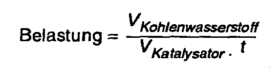


- mMaleinsäureanhydrid
- Masse an produziertem Maleinsäureanhydrid [g]
- VKatalysator
- Schüttvolumen Katalysator, summiert über alle Reaktidnszonen [l]
- t
- Zeiteinheit [h]
- VKohlenwasserstoff
- auf 0°C und 0,1013 MPa normiertes Volumen des Kohlenwasserstoffs in der Gasphase [N1] (Rechnerische Größe. Liegt ein Kohlenwasserstoff unter diesen Bedingungen in der Flüssigphase vor, so wird über das ideale Gasgesetz das hypothetische Gasvolumen berechnet.)
- U
- Umsatz an Kohlenwasserstoffen pro Reaktordurchgang
- S
- Selektivität bzgl. Maleinsäureanhydrid pro Reaktordurchgang
- A
- Ausbeute an Maleinsäureanhydrid pro Reaktordurchgang
- nKW, Reaktor, ein
- Stoffmengenstrom an Kohlenwasserstoffen am Reaktoreingang [mol/h]
- nKW, Reaktor, aus
- Stoffmengenstrom an Kohlenwasserstoffen am Reaktorausgang [mol/h]
- nKW, Anlage, ein
- Stoffmengenstrom an Kohlenwasserstoffen am Eingang der Anlage [mol/h]
- nKW, Anlage, aus
- Stoffmengenstrom an Kohlenwasserstoffen am Ausgang der Anlage [mol/h]
- nMSA, Reaktor, aus
- Stoffmengenstrom an Maleinsäureanhydrid am Reaktorausgang [mol/h]
- DMSA, Anlage, aus
- Stoffmengenstrom an Maleinsäureanhydrid am Ausgang der Anlage [mol/h]
- Die Bestimmung der mittleren Oxidationsstufe des Vanadiums erfolgte über potentiometrische Titration.
- Zur Bestimmung werden jeweils 200 bis 300 mg der Probe unter Argonatmosphäre in eine Mischung aus 15 mL 50%-iger Schwefelsäure und 5 mL 85%-iger Phosphorsäure gegeben und unter Erwärmen gelöst. Die Lösung wird anschließend in ein Titrationsgefäß, welches mit zwei Pt-Elektroden ausgestattet ist, überführt. Die Titrationen werden jeweils bei 80°C durchgeführt. Zuerst erfolgt eine Titration mit 0,1 molarer Kaliumpermanganat-Lösung. Werden zwei Stufen in der potentiometrischen Kurve erhalten, so lag das Vanadium in einer mittleren Oxidationsstufe von· +3 bis kleiner +4 vor. Wird nur eine Stufe erhalten, so lag das Vanadium in einer Oxidationsstufe von +4 bis kleiner +5 vor.
- Bei dem erstgenannten Fall (zwei Stufen / +3 ≤ Vox < +4) enthält die Lösung kein V5+, das heißt das gesamte Vanadium wurde titrimetrisch erfaßt. Über den Verbrauch der 0,1 molaren Kaliumpermanganat-Lösung und der Lage der beiden Stufen wird die Menge an V3+ und V4+ berechnet. Der gewichtete Mittelwert ergibt dann die mittlere Oxidationsstufe.
- Bei dem zweitgenannten Fall (eine Stufe / +4 ≤ Vox < +5) kann aus dem Verbrauch der 0,1 molaren Kaliumpermanganat-Lösung die Menge an V4+ berechnet werden. Durch anschließende Reduktion des gesamten V5+ der erhaltenen Lösung mit einer 0,1 molaren Ammoniumeisen(II)-sulfat-Lösung und erneute Oxidation mit 0,1 molarer Kaliumpermanganat-Lösung kann die Gesamtmenge an Vanadium berechnet werden. Die Differenz zwischen der Gesamtmenge an Vanadium und der Menge an V4+ ergibt die ursprünglich vorhandene Menge an V5+. Der gewichtete Mittelwert ergibt dann die mittlere Oxidationsstufe.
- Zur Bestimmung der Seitendruckfestigkeit wurden in nacheinander folgenden Messungen die Hohlzylinder mit der gerundeten Seitenfläche jeweils auf die plane Metall-Auflageplatte einer entsprechenden Meßeinrichtung gestellt. Die beiden planparallelen Dekkelflächen befanden sich somit in vertikaler Richtung. Nun wurde ein planer Metall-Stempel von oben mit einer Vorschubgeschwindigkeit von 1,6 mm/min auf den Hohlzylinder zugefahren und der zeitliche Verlauf der Krafteinwirkung auf den Hohlzylinder bis zu dessen Bruch aufgezeichnet. Die Seitendruckfestigkeit des einzelnen Hohlzylinders entspricht der maximal eingewirkten Kraft.
- Zur Bestimmung der Seitendruckfestigkeit wurden unter Mittelwertbildung jeweils 30 Einzelmessungen durchgeführt.
- Die geometrische Dichte der Hohlzylinder ist definiert als der Quotient der Masse zum geometrischen Volumen der Hohlzylinder. Das geometrische Volumen ergibt sich aus den äußeren, makroskopischen Abmessungen der Hohlzylinder unter Berücksichtigung des äußeren Durchmessers, der Höhe und des Durchmessers des inneren Lochs.
- Zur Bestimmung der geometrischen Dichte wurde eine statistisch belastbare Menge an Hohlzylindern vermessen, deren Masse bestimmt und die geometrischen Dichte rechnerisch ermittelt.
- Zur Bestimmung der mechanischen Stabilität durch den Falltest wurden etwa 50 g geometrisch intakter und entstaubter Hohlzylinder durch ein 6,5 m langes Rohr mit einem Innendurchmesser von 21 mm nacheinander fallen gelassen und am Ende des Rohres mit einer Porzellanschale aufgefangen. Die aufgefangene Menge wurde anschließend per Hand sortiert und der Massenanteil der beschädigten Hohlzylinder (Hohlzylinder mit Rissen oder abgeplatzten Kanten, zertrümmerte Hohlzylinder, Bruchstücke, Splitter) bestimmt. Der Ausschuß nach dem Falltest ergibt sich nun aus dem Quotienten der Masse der beschädigten Hohlzylinder zur ursprünglich eingewogenen Masse.
- Zur Bestimmung des Abriebs wurden etwa 50 g entstaubter Hohlzylinder in eine Plexiglastrommel mit einem Innendurchmesser von 290 mm, einer Trommelhöhe von 40 mm und einem zwischen Drehachse und Außenwandung befindlichen, mit der Plexiglastrommel fest verbundenen, kreisförmig gekrümmten (Radius 80 mm) Plexiglaseinbau, welcher die gesamte Trommelhöhe von 40 mm umfasst, gegeben. Nun wurde die Plexiglastrommel, deren Drehachse sich in horizontaler Richtung befand, 18 Minuten lang mit 25 Umdrehungen pro Minute gedreht. Anschließend wurde der Abrieb der Probe abgesiebt, die verbliebenen Partikel entstaubt und zurückgewogen. Der Abriebswert ergibts sich nun aus dem Quotienten der Verlustmasse zur ursprünglich eingewogenen Masse.
- Die Versuchsanlage war ausgestattet mit einer Zufuhr-Einheit und einem Reaktorrohr. Der Ersatz eines Rohrbündelreaktors durch ein Reaktorrohr ist im Labor- oder Technikumsmaßstab sehr gut möglich, sofern die Abmessungen des Reaktorrohres im Bereich eines technischen Reaktorrohres liegen. Die Anlage wurde im "geraden Durchgang" betrieben.
- Der Kohlenwasserstoff wurde mengengeregelt in flüssiger Form über eine Pumpe zugegeben. Als Sauerstoff-haltiges Gas wurde Luft mengengeregelt zugegeben. Triethylphosphat (TEP) wurde ebenfalls mengengeregelt, gelöst in Wasser, in flüssiger Form zugegeben.
- Die RohrbündAlreaktor-Einheit bestand aus einem Rohrbündelreaktor mit einem Reaktorrohr. Die Länge des Reaktorrohrs betrug 6,5 m, der Innendurchmesser'22,3 mm. Innerhalb des Reaktorrohres befand sich in einem Schutzrohr mit 6 mm Außendurchmesser ein Multi-Thermoelement mit 20 Temperaturmeßstellen. Das Reaktorrohr war von einem temperierbaren Wärmeträger-Kreislauf umgeben und wurde von dem Reaktionsgasgemisch von oben nach unten durchströmt. Die oberen 0,3 m des Reaktorrohres waren mit Inertmaterial gefüllt und bildeten die Vorheizzone. Die Reaktionszone enthielt jeweils 2,2 L Katalysator. Als Wärmeträgermedium wurde eine Salzschmelze eingesetzt.
- Direkt nach der Rohrbündelreaktor-Einheit wurde gasförmiges Produkt entnommen und der gaschromatographischen on-line Analytik zugeführt. Der Hauptstrom des gasförmigen Reaktoraustrags wurde aus der Anlage ausgeschleust.
- Die Anlage wurde wie folgt betrieben:
Konzentration an n-Butan am Reaktoreingang = 2,0 Vol.-% GHSV = 2000 Nl/lKatalysator · h Druck am Reaktorausgang = 0,2 MPa abs Konzentration an Triethylphosphat (TEP) = 2 Volumen-ppm Konzentration an Wasserdampf = 1,5 Vol.-% - In einem mit Stickstoff inertisierten, über Druckwasser außenbeheizbaren 8 m3-Stahl/Email-Rührkessel mit Strombrechern wurden 6,1 m3 Isobutanol vorgelegt. Nach Inbetriebnahme des dreistufigen Impellerrührers wurde das Isobutanol unter Rückfluß auf 90°C aufgeheizt. Bei dieser Temperatur wurde nun über die Förderschnecke mit der Zugabe von 736 kg Vanadiumpentoxid begonnen. Nachdem nach ca. 20 Minuten etwa 2/3 der gewünschten Menge an Vanadiumpentoxid zugegeben wurden, wurde bei weiterer Zugabe an Vanadiumpentoxid mit der Einpumpung von 900 kg 105%-iger Phosphorsäure begonnen. Zur Reinigung der Pumpe wurden weitere 0,2 m3 Isobutanol nachgepumpt. Anschließend wurde das Reaktionsgemisch unter Rückfluß auf etwa 100 bis 108°C erhitzt und unter diesen Bedingungen 14 Stunden belassen. Im Anschluß daran wurde die heiße Suspension in eine zuvor mit Stickstoff inertisierte und beheizte Druckfilternutsche abgelassen und bei einer Temperatur von etwa 100°C bei einem Druck oberhalb der Filternutsche von bis zu 0,35 MPa abs abfiltriert. Der Nutschkuchen wurde durch stetiges Einleiten von Stickstoff bei 100°C und unter Rühren mit einem mittig angeordneten, in der Höhe verstellbaren Rührer innerhalb von etwa einer Stunde trokkengeblasen. Nach dem Trockenblasen wurde auf ca. 155°C aufgeheizt und auf einen Druck von 15 kPa abs (150 mbar abs) evakuiert. Die Trocknung wurde bis zu einem Rest-Isobutanolgehalt von < 2 Gew.-% im getrockneten Katalysator-Precursor durchgeführt.
- Anschließend wurde das getrocknete Pulver 2 Stunden unter Luft in einem Drehrohr mit einer Länge von 6,5 m, einem Innendurchmesser von 0,9 m und innenliegenden spiralförmigen Wendeln behandelt. Die Drehzahl des Drehrohres betrug 0,4 U/min. Das Pulver wurde in einer Menge von 60 kg/h in das Drehrohr gefördert. Die Luftzufuhr betrug 100 m3/h. Die direkt an der Außenseite des Drehrohrs gemessenen Temperaturen der fünf gleichlangen Heizzonen betrugen 250°C, 300°C, 340°C, 340°C und 340°C. Nach dem Abkühlen auf Raumtemperatur wurde der VPO-Precursor mit 1 Gew.-% Graphit innig vermischt und in einem Walzen-Kompaktor kompaktiert. Das Feingut im Kompaktat mit einer Partikelgröße < 400 µm wurde abgesiebt und erneut der Kompaktierung zugeführt. Das Grobgut mit einer Partikelgröße ≥ 400 µm wurde mit weiteren 2 Gew.-% Graphit vermischt und in einer Tablettiermaschine zu 5x3x2,5 mm Hohlzylindern (äußerer Durchmesser x Höhe x Durchmesser des inneren Lochs) mit einer Seitendruckfestigkeit von 11 N tablettiert. Um die erforderliche Menge an Katalysatorprecursor zu erhalten, wurden mehrere Ansätze durchgeführt.
- Etwa 2,7 t der erhaltenen 5x3x2,5 mm Hohlzylindern (siehe "Herstellung des Katalysatorprecursors") wurden in einer Schütthöhe von 9 bis 10 cm kontinuierlich auf das gasdurchlässige Förderband einer Bandkalziniervorrichtung aus zwei hintereinandergeschalteten, identischen Bandkalzinierapparaten mit insgesamt acht Kalzinierzonen gegeben. Die ersten 1,4 t wurden zur einmaligen Einstellung der Betriebsparameter der Bandkalziniervorrichtung verwendet. Da sie kein einheitliches Material darstellten, wurden sie im Folgenden nicht weiter betrachtet.
- Die Bandkalziniervorrichtung wurde bei Atmosphärendruck betrieben. Zwischen den Kalzinierzonen 4 und 5 befand sich eine umkapselte Übergangszone. Jede der acht Kalzinierzonen umfasste zur Erzeugung einer Gaszirkulation jeweils einen Ventilator. Jede der acht Kalzinierzonen wurde mit der gewünschten Menge an gewünschtem Frischgas versorgt. Zur Erhaltung des gewünschten Atmosphärendrucks wurde eine entsprechende Gasmenge abgeführt. Das Volumen des pro Zeiteinheit in jeder Kalzinierungszone zirkulierenden Gases war größer als das Volumen des pro Zeiteinheit zu- oder abgeführten Gases. Zwischen zwei aufeinanderfolgenden Kalzinierungszonen befand sich zur Verringerung des Gasaustausches jeweils eine Trennwand, welche im Bereich des Stromes des Katalysatorprecursors offen war. Die Länge jeder Kalzinierzone ln betrug 1,45 m. Die Geschwindigkeit des Förderbandes wurde entsprechend der gewünschten Verweilzeit von etwa 2 Stunden pro Kalzinierzone eingestellt. Die einzelnen Zonen wurden wie in Tabelle 2 dargestellt betrieben:
Tabelle 2: Parameter zum Betrieb der Bandkalziniervorrichtung. Zone Temperatur zugeführtes Frischgas Kalzinierzone 1 Aufheizen auf 250°C Luft Kalzinierzone 2 Halten bei 250°C Luft Kalzinierzone 3 Halten bei 250°C Luft Kalzinierzone 4 Aufheizen auf 310°C Luft Übergangszone Abkühlen auf 200°C Luft Kalzinierzone 5 Aufheizen auf 425°C N2 Kalzinierzone 6 Halten bei 425°C N2/H2O-Dampf (1:1) Kalzinierzone 7 Halten bei 425°C N2/H2O-Dampf (1:1) Kalzinierzone 8 Abkühlen auf Raumtemperatur N2 - Innerhalb aller acht Kalzinierzonen betrug die zeitliche Schwankung der Gastemperatur an jeder Stelle im Bereich des Stromes des Katalysatorprecursors nach der halben Länge der Kalzinierungszone ln/2 jeweils ≤ 1,2°C und die lokale Differenz der Gastemperatur zwischen beliebigen Stellen im Bereich des Stromes des Katalysatorprecursors nach der halben Länge der Kalzinierungszone ln/2 jeweils ≤ 1,5°C. Auf diese Weise wurden ca. 1,3 t fertiger Katalysator kontinuierlich hergestellt.
- Während der Herstellung wurden in gegebenen Abständen Proben des fertigen Katalysators entnommen und hinsichtlich der mittleren Oxidationsstufe des Vanadiums, der Seitendruckfestigkeit und der geometrischen Dichte analysiert. Die erhaltenen Ergebnisse sind in Tabelle 3 wiedergegeben.
- Wie den Ergebnissen zu entnehmen ist, kann durch das erfindungsgemäße Verfahren die für die Einstellung der Aktivität und Selektivität des Katalysators wichtige Größe der mittleren Oxidationsstufe des Vanadiums sicher handhabbar in einem sehr engen Bereich gehalten werden. Bei einem Mittelwert von 4,16 betrug der niedrigste gemessene Wert 4,14 und der höchste gemessene Wert 4,17.
- Auch die Seitendruckfestigkeit und die geometrische Dichte konnte in engen Grenzen von 8,4 bis 11,4 N bei einem Mittelwert von 10,1 N sowie von 1,51 bis 1,58 g/mL bei einem Mittelwert von 1,55 g/mL gehalten werden. Der geringe Ausschuß nach dem Falltest und der gemessene Abrieb bestätigen die enge Streubreite ebenfalls.
- Mit einer repräsentativ ausgewählten Einzelprobe von 2,2 L des erfindungsgemäß hergestellten Katalysators aus Beispiel 1 wurde in der ober beschriebenen Versuchsanlage ein katalytischer Performancetest durchgeführt. Die Salzbadtemperatur wurde dabei derart eingestellt, dass ein n-Butan-Umsatz von etwa 85% resultierte. Die erhaltenen Ergebnisse sind in Tabelle 5 wiedergegeben.
- Etwa 0,4 t der erhaltenen 5x3x2,5 mm Hohlzylindern (siehe "Herstellung des Katalysatorprecursors") wurden in einer Schütthöhe von 4 bis 5 cm auf gasdurchlässigen Blechen der Abmessung 0,5 × 1 m in einen Hordenofen gegeben. Der Hordenofen umfasste dabei insgesamt zehn Bleche in zwei nebeneinander befindlichen Reihen und war mit einer externen Gaszirkulation ausgestattet. Das zuvor entnommene und mit der gewünschten Menge an Frischgas angereicherte Gas wurde seitlich in den Hordenofen geleitet. Der kontinuierliche Gasabzug erfolgte mittig auf der Oberseite des Hordenofens. Dem entnommenen Gas wurde kontinuierlich die gewünschte Menge an Frischgas zugeführt, über einen Wärmetauscher und ein Gebläse geleitet und wie zuvor beschrieben dem Hordenofen wieder seitlich zugeführt. Der Hordenofen wurde bei einem geringen Überdruck von 3 kPa (30 mbar) betrieben. Zur Erhaltung des gewünschten Drucks wurde eine entsprechende Gasmenge nach dem Gebläse kontinuierlich abgeführt.
- Zur Kalzinierung des Katalysatorprecursors wurde dieser im Hordenofen in einer Gasatmosphäre aus 2,5 Vol.-% Sauerstoff in Stickstoff mit einer Temperaturrampe von 2°C/min auf 350°C erhitzt und 25 Minuten unter diesen Bedingungen belassen. Es wurde stets frisches Gasgemisch zugeführt. Anschließend wurde die Gasatmosphäre durch eine Stickstoff-Wassersdampf-Atmosphäre (1:1) ausgetauscht und der Katalysatorprecursor mit 4°C/min auf 450°C aufgeheizt und 4 Stunden belassen. Zuletzt wurde unter einer Stickstoff-Atmosphäre abgekühlt.
- Die im Vergleichsbeispiel (Beispiel 2) eingestellten Kalzinierungsbedingungen wurden in Vorversuchen im Hinblick auf die Herstellung eines Katalysators mit gegenüber dem Katalysator nach dem erfindungsgemäßen Beispiel 1 möglichst identischer mittlerer Oxidationsstufe des Vanadiums optimiert. Die Unterschiede in den einzelnen Parametern sind somit durch die erforderliche Optimierung begründet.
- Nach der Kalzinierung wurden von beliebig ausgesuchten Stellen der Bleche Proben entnommen und hinsichtlich der mittleren Oxidationsstufe des Vanadiums, der Seitendruckfestigkeit und der geometrischen Dichte analysiert. Die erhaltenen Ergebnisse sind in Tabelle 4 aufgeführt.
Tabelle 4: Charakterisierung des im Hordenofen kalzinierten Katalysators. Katalysatorprobe (Nummer) Vox. SDF [N] geometrische Dichte dp [g/mL] 1 4,05 9 1,53 2 4,20 14 1,68 3 4,05 9 1,57 4 4,20 12 1,68 Mittelwert: 4,13 11 1,62 Vox. = mittlere Oxidationsstufe des Vanadiums SDF = Seitendruckfestigkeit - Gegenüber den Charakterisierungsdaten des erfindungsgemäß durch kontinuierliche Kalzinierung in einer Bandkalziniervorrichtung kalzinierten Katalysators zeigt der diskontinuierlich im Hordenofen kalzinierte Katalysator sehr große Streubreiten. So variiert die mittlere Oxidationsstufe des Vanadiums der statistisch ausgewählten Proben von 4,05 bis 4,20, wobei der rechnerisch ermittelte Mittelwert bei 4,13 liegt. Auch die Seitendruckfestigkeit und die geometrische Dichte zeigen eine breite Streuung von 9 bis 14 N bei einem Mittelwert von 11 N beziehungsweise von 1,53 bis 1,68 g/mL bei einem Mittelwert von 1,62 g/mL.
- Mit 2,2 L einer statistischen Mischung des diskontinuierlich im Hordenofen kalzinierten Katalysators aus Beispiel 3 wurde in der ober beschriebenen Versuchsanlage ein katalytischer Performancetest durchgeführt. Die Salzbadtemperatur wurde dabei derart eingestellt, dass ein n-Butan-Umsatz von etwa 85% resultierte. Die erhaltenen Ergebnisse sind in Tabelle 5 wiedergegeben.
Tabelle 5: Ergebisse der katalytischen Tests Katalysator nach Beispiel 1 (Kontinuierliche Kalzination im Bandkalzinierer) Katalysator nach Beispiel 3 (Diskontinuierliche Kalzination im Hordenofen) Salzbadtemperatur [°C] 395 410 Temperatur des Hot Spots [°C] 425 434 Druckverlust [MPa] 0,13 0,13 Umsatz U [%] 84,8 85,0 Ausbeute A [%] 57,5 56,7 - Ein Vergleich der Ergebnisse mit denen des erfindungsgemäß hergestellten Katalysators von Beispiel 1 zeigt, dass aufgrund der, großen Streubreite des Vergleichskatalysators eine um 15°C höhere Salzbadtemperatur (410°C gegenüber 395°C) zur Einstellung der 85% n-Butan-Umsatz erforderlich ist. Als Folge davon wird beim Vergleichskatalysator eine um 9°C höhere Hot-Spot-Temperatur erreicht. Das niedrigere Temperaturniveau, welches beim erfindungsgemäßen Katalysator erreicht wird, ist aus vielen Gründen vorteilhaft. So wird beispielsweise der Katalysator thermisch geringer belastet, was zu einer höheren Lebensdauer führt. Die Gefahr des "Durchgehens" der Reaktion ist ebenfalls aufgrund des niedrigeren Temperaturniveaus vermindert. Des weiteren arbeitet der Katalysator selektiver, was bei gleichem Umsatz zu einer höheren Ausbeute an Wertprodukt führt. Dies ist auch aus den experimentellen Daten ersichtlich (57,5% Ausbeute beim erfindungsgemäß hergestellten Katalysator gegenüber 56,7% Ausbeute im Vergleichsbeispiel).
Tabelle 3: Charakterisierung des erfindungsgemäß hergestellten Katalysators. Katalysatorprobe nach Vox. SDF [N] geometrische Dichte dp Ausschuß nach Fall- Abrieb x t [g/mL] test[Gew.-%] [Gew.-%] 1,47 4,16 8,7 1,51 2,0 0,8 1,70 4,16 10,1 1,55 3,6 0,4 1,99 4,16 9,9 1,55 4,7 0,9 2,19 4,14 11,2 1,55 3,5 0,7 2,35 4,15 8,4 1,56 3,3 0,7 2,51 4,17 11,4 1,58 2,1 0,9 2,67 4,17 11,3 1,58 4,0 n.b. Mittelwert: 4,16 10,1 1,55 3,3 0,7 n.b. = nicht bestimmt
Vox = mittlere Oxidationsstufe des Vanadiums
SDF = Seitendruckfestigkeit
Claims (9)
- Verfahren zur Herstellung eines für die heterogenkatalytische Gasphasenoxidation eines Kohlenwasserstoffs mit mindestens vier Kohlenstoffatomen zu Maleinsäureanhydrid geeigneten, Vanadium, Phosphor und Sauerstoff enthaltenden Katalysators, bei dem man einen entsprechenden Vanadium, Phosphor und Sauerstoff enthaltenden Katalysatorprecursor, welcher Partikel mit einem gemittelten Durchmesser von mindestens 2 mm aufweist, durch Kalzinierung in eine katalytisch aktive Form überführt, daduch gekennzeichnet, dass man einen Strom des Katalysatorprecursors zur Kalzinierung mit im Wesentlichen konstanter Geschwindigkeit auf. einem Förderband durch mindestens eine Kalzinierungszone n der Länge ln führt, wobei die zeitliche Schwankung der Gastemperatur vom Sollwert an jeder Stelle im Bereich des Stromes des Katalysatorprecursors nach der halben Länge der Kalzinierungszone ln/2 jeweils ≤ 5°C und die lokale Differenz der Gastemperatur zwischen beliebigen Stellen im Bereich des Stromes des Katalysatorprecursors nach der halben Länge der Kalzinierungszone ln/2 jeweils ≤ 5°C betragen, und dadurch gekennzeichnet, dass man den Katalysatorprecursor(a) in mindestens einer Kalzinierungszone in einer oxidierenden Atmosphäre mit einem Sauerstoff-Gehalt von 2 bis 21 Vol.-% auf eine Temperatur von 200 bis 350°C aufheizt und unter diesen Bedingungen bis zur Einstellung der gewünschten mittleren Oxidationsstufe des Vanadiums beläßt; und(b) in mindestens einer weiteren Kalzinierungszone in einer nicht-oxidierenden Atmosphäre mit einem Sauerstoff-Gehalt von ≤ 0,5 Vol. -% und einem Wasserstoffoxid-Gehalt von 20 bis 75 Vol.-% auf eine Temperatur von 300 bis 50.0°C aufheizt und ≥ 0,5 Stunden unter diesen Bedingungen beläßt.
- Verfahren nach Anspruch 1, dadurch gekennzeichnet, dass man ein gasdurchlässiges Förderband einzetzt und in der Kalzinierungszone n senkrecht zur Fortbewegungsrichtung des Katalysatorprecursors einen Gasstrom durch den Strom des Katalysatorprecursors leitet.
- Verfahren nach den Ansprüchen 1 bis 2, dadurch gekennzeichnet, dass man in der Kalzinierungszone n eine Gaszirkulation einstellt, bei der das Volumen des pro Zeiteinheit in der Kalzinierungszone n zirkulierenden Gases größer ist als das Volumen des pro Zeiteinheit in der Kalzinierungszone n zugeführten Gases.
- Verfahren nach Anspruch 3,' dadurch gekennzeichnet, dass man zum Erzeugen der Gaszirkulation einen Ventilator einsetzt.
- Verfahren nach den Ansprüchen 1 bis 4, dadurch gekennzeichnet, dass die zeitliche Schwankung der Gastemperatur vom Sollwert an jeder Stelle im Bereich des Stromes des Katalysatorprecursors nach der halben Länge der Kalzinierungszone ln/2 jeweils ≤ 2°C beträgt.
- Verfahren nach den Ansprüchen 1 bis 5, dadurch gekennzeichnet, dass die lokale Differenz der Gastemperatur zwischen beliebigen Stellen im Bereich des Stromes des Katalysatorprecursors nach der halben Länge der Kalzinierungszone ln/2 ≤ 3°C beträgt.
- Verfahren nach den Ansprüchen 1 bis 6, dadurch gekennzeichnet, dass man den Strom des Katalysatorprecursors zur Kalzinierung durch mindestens zwei Kalzinierungszonen führt und die Temperaturen der einzelnen Kalzinierungszonen voneinander unabhängig regelbar sind.
- Verfahren nach den Ansprüchen 1 bis 7, dadurch gekennzeichnet, dass man einen Katalysatorprecursor einsetzt, welcher im Wesentlichen eine hohlzylinderförmige Struktur aufweist.
- Verfahren nach den Ansprüchen 1 bis 8, dadurch gekennzeichnet, dass man einen Katalysator herstellt, welcher ein Phosphor/Vanadium-Atomverhältnis von 0,9 bis 1,5, eine mittlere Oxidationsstufe des Vanadiums von +3,9 bis +4,4, eine BET-Oberfläche von 10 bis 50 m2/g, ein Porenvolumen von 0,1 bis 0,5 ml/g und eine Schüttdichte von 0,5 bis 1,5 kg/l aufweist.
Applications Claiming Priority (3)
| Application Number | Priority Date | Filing Date | Title |
|---|---|---|---|
| DE10211446A DE10211446A1 (de) | 2002-03-15 | 2002-03-15 | Verfahren zur Herstellung eines Vanadium, Phosphor und Sauerstoff enthaltenden Katalysators |
| DE10211446 | 2002-03-15 | ||
| PCT/EP2003/002502 WO2003078310A2 (de) | 2002-03-15 | 2003-03-12 | Verfahren zur herstellung eines vanadium, phosphor und sauerstoff enthaltenden katalysators |
Publications (3)
| Publication Number | Publication Date |
|---|---|
| EP1487575A2 EP1487575A2 (de) | 2004-12-22 |
| EP1487575B1 EP1487575B1 (de) | 2005-12-14 |
| EP1487575B2 true EP1487575B2 (de) | 2009-04-01 |
Family
ID=27797793
Family Applications (1)
| Application Number | Title | Priority Date | Filing Date |
|---|---|---|---|
| EP03708212A Expired - Lifetime EP1487575B2 (de) | 2002-03-15 | 2003-03-12 | Verfahren zur herstellung eines vanadium, phosphor und sauerstoff enthaltenden katalysators |
Country Status (9)
| Country | Link |
|---|---|
| US (1) | US7060649B2 (de) |
| EP (1) | EP1487575B2 (de) |
| JP (1) | JP4382496B2 (de) |
| KR (1) | KR20040093144A (de) |
| CN (1) | CN1284623C (de) |
| AT (1) | ATE312664T1 (de) |
| AU (1) | AU2003212333A1 (de) |
| DE (2) | DE10211446A1 (de) |
| WO (1) | WO2003078310A2 (de) |
Families Citing this family (36)
| Publication number | Priority date | Publication date | Assignee | Title |
|---|---|---|---|---|
| DE10323818A1 (de) | 2003-05-23 | 2004-12-09 | Basf Ag | Katalysatorsysteme zur Herstellung von Phthalsäureanhydrid |
| DE10334582A1 (de) | 2003-07-28 | 2005-02-24 | Basf Ag | Verfahren zur Herstellung von Maleinsäureanhydrid |
| US7629286B2 (en) * | 2005-05-02 | 2009-12-08 | Ineos Usa Llc | Phosphorus addition process for improvement of catalysts suitable for maleic anhydride production |
| US20070270597A1 (en) * | 2006-05-18 | 2007-11-22 | Basf Aktiengesellschaft | Process for preparing maleic anhydride in a microchannel reactor |
| WO2008087116A1 (de) * | 2007-01-19 | 2008-07-24 | Basf Se | Verfahren zur herstellung von katalysatorformkörpern, deren aktivmasse ein multielementoxid ist |
| DE102007004961A1 (de) | 2007-01-26 | 2008-07-31 | Basf Se | Verfahren zur Herstellung von Katalysatorformkörpern, deren Aktivmasse ein Multielementoxid ist |
| WO2008116810A1 (de) | 2007-03-23 | 2008-10-02 | Basf Se | Verfahren zur destillativen gewinnung von maleinsäureanhydrid |
| DE102007017080A1 (de) | 2007-04-10 | 2008-10-16 | Basf Se | Verfahren zur Beschickung eines Längsabschnitts eines Kontaktrohres |
| DE102007025869A1 (de) | 2007-06-01 | 2008-07-03 | Basf Se | Verfahren der Wiederbeschickung der Reaktionsrohre eines Rohrbündelreaktors mit einem neuen Katalysatorfestbett |
| DE102007028332A1 (de) | 2007-06-15 | 2008-12-18 | Basf Se | Verfahren zum Beschicken eines Reaktors mit einem Katalysatorfestbett, das wenigstens ringförmige Katalysatorformkörper K umfasst |
| CN101952038B (zh) | 2007-10-22 | 2013-04-24 | 亨斯迈石油化学有限责任公司 | 用于马来酸酐生产的改进的氧化催化剂 |
| EP2212022A4 (de) * | 2007-11-09 | 2012-09-12 | Univ Putra Malaysia | Verbessertes verfahren von hochoberflächigem nanopartikulärem vanadiumphosphoroxid-katalysator und davon abgeleitetes produkt |
| DE102008040094A1 (de) | 2008-07-02 | 2009-01-29 | Basf Se | Verfahren zur Herstellung eines oxidischen geometrischen Formkörpers |
| DE102008040093A1 (de) | 2008-07-02 | 2008-12-18 | Basf Se | Verfahren zur Herstellung eines ringähnlichen oxidischen Formkörpers |
| US8728972B2 (en) * | 2008-10-21 | 2014-05-20 | Huntsman Petrochemical Llc | High pore volume VPO catalyst for maleic anhydride production |
| DE102008054586A1 (de) | 2008-12-12 | 2010-06-17 | Basf Se | Verfahren zur kontinuierlichen Herstellung von geometrischen Katalysatorformkörpern K |
| KR20110110303A (ko) | 2009-01-12 | 2011-10-06 | 바스프 에스이 | 폴리메틸올의 제조 방법 |
| DE102010040921A1 (de) | 2010-09-16 | 2012-03-22 | Basf Se | Verfahren zur Herstellung von Acrylsäure aus Methanol und Essigsäure |
| DE102010040923A1 (de) | 2010-09-16 | 2012-03-22 | Basf Se | Verfahren zur Herstellung von Acrylsäure aus Ethanol und Formaldehyd |
| CN102161005A (zh) * | 2011-02-21 | 2011-08-24 | 化学工业第二设计院宁波工程有限公司 | 乙酸和甲醛合成丙烯酸用磷钒催化剂的制备方法 |
| US9573119B2 (en) | 2011-09-16 | 2017-02-21 | Eastman Chemical Company | Process for preparing V—Ti—P catalysts for synthesis of 2,3-unsaturated carboxylic acids |
| US8883672B2 (en) | 2011-09-16 | 2014-11-11 | Eastman Chemical Company | Process for preparing modified V-Ti-P catalysts for synthesis of 2,3-unsaturated carboxylic acids |
| US8993801B2 (en) | 2011-09-16 | 2015-03-31 | Eastman Chemical Company | Process for preparing V-Ti-P catalysts for synthesis of 2,3-unsaturated carboxylic acids |
| US8765629B2 (en) | 2011-09-16 | 2014-07-01 | Eastman Chemical Company | Process for preparing V-Ti-P catalysts for synthesis of 2,3-unsaturated carboxylic acids |
| DE102012012510B4 (de) | 2012-06-22 | 2018-12-06 | Clariant International Ltd. | Graphithaltiger Katalysatorformkörper, dessen Herstellverfahren sowie Verwendung |
| DE102013008207A1 (de) | 2013-05-14 | 2014-11-20 | Basf Se | Verfahren zur Herstellung von Acrylsäure mit hoher Raum-Zeit-Ausbeute |
| US9073846B2 (en) | 2013-06-05 | 2015-07-07 | Celanese International Corporation | Integrated process for the production of acrylic acids and acrylates |
| US9120743B2 (en) | 2013-06-27 | 2015-09-01 | Celanese International Corporation | Integrated process for the production of acrylic acids and acrylates |
| DE102015108860A1 (de) * | 2015-06-03 | 2016-12-08 | Thyssenkrupp Ag | Verfahren und Vorrichtung zur Durchführung von Stoffaustauschvorgängen, Stofftrennvorgängen und/oder Reaktionen unter Beteiligung mindestens einer stationären und mindestens einer mobilen Phase |
| US11289700B2 (en) | 2016-06-28 | 2022-03-29 | The Research Foundation For The State University Of New York | KVOPO4 cathode for sodium ion batteries |
| US11493274B2 (en) * | 2019-12-04 | 2022-11-08 | Greyrock Technology, Llc | Process for the commercial production of high-quality catalyst materials |
| CN110624593A (zh) * | 2019-09-30 | 2019-12-31 | 陕西科技大学 | 一种VN@Co电催化剂的制备方法 |
| US12515204B2 (en) | 2020-05-26 | 2026-01-06 | Basf Se | Shaped catalyst body with improved properties, its preparation and use |
| EP3805194A1 (de) * | 2020-09-25 | 2021-04-14 | Basf Se | Verfahren zur herstellung eines multimetalloxid-katalysators unter gasdichten bedingungen |
| CN114433149B (zh) * | 2020-10-30 | 2023-09-01 | 中国石油化工股份有限公司 | 一种钒磷氧催化剂,其制备方法及应用 |
| CN114433150B (zh) * | 2020-10-30 | 2023-09-01 | 中国石油化工股份有限公司 | 一种钒磷氧催化剂 |
Citations (1)
| Publication number | Priority date | Publication date | Assignee | Title |
|---|---|---|---|---|
| US4699985A (en) † | 1985-07-15 | 1987-10-13 | E. I. Du Pont De Nemours And Company | Process for oxidation of N-butane to maleic anhydride |
Family Cites Families (17)
| Publication number | Priority date | Publication date | Assignee | Title |
|---|---|---|---|---|
| FR2524131A1 (fr) * | 1982-03-25 | 1983-09-30 | Glaskuhl Sa | Appareil pour le traitement thermique d'objets par convection |
| US4567158A (en) * | 1983-12-28 | 1986-01-28 | Monsanto Company | Process for preparing phosphorus-vanadium mixed oxide oxidation catalysts |
| US4677084A (en) * | 1985-11-27 | 1987-06-30 | E. I. Du Pont De Nemours And Company | Attrition resistant catalysts, catalyst precursors and catalyst supports and process for preparing same |
| US4719332A (en) * | 1986-05-05 | 1988-01-12 | Strategic Products, Inc. | Tube shrinking oven |
| DE3787007T2 (de) * | 1986-12-19 | 1994-01-20 | Babcock Hitachi Kk | Verfahren zur Kalzinierung eines Denitrierungskatalyators. |
| US4996179A (en) * | 1989-01-17 | 1991-02-26 | Amoco Corporation | Maleic anhydride catalysts and process for their manufacture |
| US5168090A (en) * | 1990-10-04 | 1992-12-01 | Monsanto Company | Shaped oxidation catalyst structures for the production of maleic anhydride |
| US5137860A (en) * | 1991-06-27 | 1992-08-11 | Monsanto Company | Process for the transformation of vanadium/phosphorus mixed oxide catalyst precursors into active catalysts for the production of maleic anhydride |
| US5275996A (en) * | 1992-05-22 | 1994-01-04 | Monsanto Company | Phosphorous/vanadium oxide catalyst and process of preparation thereof |
| US5506187A (en) * | 1992-12-18 | 1996-04-09 | Amoco Corporation | Catalysts for the production of maleic anhydride by the oxidation of butane |
| US5530144A (en) * | 1993-12-22 | 1996-06-25 | Mitsubishi Chemical Corporation | Process for producing a phosphorus-vanadium oxide catalyst precursor, process for producing a phosphorus-vanadium oxide catalyst, and process for producing maleic anhydride by vapor phase oxidation using the catalyst |
| US5641722A (en) * | 1994-09-15 | 1997-06-24 | Huntsman Petrochemical Corporation | High performance VPO catalyst and process of preparation thereof |
| JPH0886571A (ja) * | 1994-09-20 | 1996-04-02 | Kao Corp | ベルトコンベア式処理装置 |
| US5945368A (en) | 1995-10-02 | 1999-08-31 | Huntsman Petrochemical Corporation | Molybdenum-modified vanadium-phosphorus oxide catalysts for the production of maleic anhydride |
| DE19955168A1 (de) * | 1999-11-16 | 2001-05-17 | Basf Ag | Verfahren der katalytischen Gasphasenoxidation von Propen zu Acrylsäure |
| DE10046072A1 (de) * | 2000-09-15 | 2002-03-28 | Basf Ag | Katalysator-Precursor für die Herstellung von Maleinsäureanhydrid |
| DE10046957A1 (de) | 2000-09-21 | 2002-04-11 | Basf Ag | Verfahren zur Herstellung eines Multimetalloxid-Katalysators, Verfahren zur Herstellung ungesättigter Aldehyde und/oder Carbonsäuren und Bandcalziniervorrichtung |
-
2002
- 2002-03-15 DE DE10211446A patent/DE10211446A1/de not_active Withdrawn
-
2003
- 2003-03-12 DE DE50301926T patent/DE50301926D1/de not_active Expired - Lifetime
- 2003-03-12 AU AU2003212333A patent/AU2003212333A1/en not_active Abandoned
- 2003-03-12 US US10/507,601 patent/US7060649B2/en not_active Expired - Fee Related
- 2003-03-12 KR KR10-2004-7014462A patent/KR20040093144A/ko not_active Withdrawn
- 2003-03-12 AT AT03708212T patent/ATE312664T1/de not_active IP Right Cessation
- 2003-03-12 WO PCT/EP2003/002502 patent/WO2003078310A2/de not_active Ceased
- 2003-03-12 CN CNB038108682A patent/CN1284623C/zh not_active Expired - Fee Related
- 2003-03-12 JP JP2003576330A patent/JP4382496B2/ja not_active Expired - Fee Related
- 2003-03-12 EP EP03708212A patent/EP1487575B2/de not_active Expired - Lifetime
Patent Citations (1)
| Publication number | Priority date | Publication date | Assignee | Title |
|---|---|---|---|---|
| US4699985A (en) † | 1985-07-15 | 1987-10-13 | E. I. Du Pont De Nemours And Company | Process for oxidation of N-butane to maleic anhydride |
Non-Patent Citations (7)
| Title |
|---|
| A.Enderlein et al., " A new Conveyor Furnace for Thick Film Firing...", International Microelectronic Symposium , Chicago,11-13.10.1971, Seiten 4-3-1 bis 4-3-4 † |
| BEGAKIS: "Short communication, An Inexpensive Thick Film Furnace", ELECTROCOMPONENT SCIENCE AND TECHNOLOGY, vol. 3, 1976, pages 113 - 115 † |
| BRIEM K.: "Wärmebehandlung von Massengutteilen....", GASWÄRMWE INTERNATIONAL, vol. 47, no. 9, September 1998 (1998-09-01), pages 439 - 444 † |
| KAZMIEROWICZ C. ET AL: "MONITORING BELT FURNACE TEMPERATURES: A NEW WAY", HYBRID CIRCUIT TECHNOLOGY, November 1988 (1988-11-01), pages 39 - 45 † |
| Kirk-Othme, Encyclopedia of Chemical Technology, 3 Auflage, Band 11 , Seiten 551-557 † |
| M.P.M.A Limpens,PhD Thesis, 01.11.2000, " A Design Tool for Conveyor Belt Furnaces, Seiten 1-90 † |
| MPR, Dezember 1996, Seite 42, " Belt Furnaces" † |
Also Published As
| Publication number | Publication date |
|---|---|
| AU2003212333A8 (en) | 2003-09-29 |
| CN1284623C (zh) | 2006-11-15 |
| DE50301926D1 (de) | 2006-01-19 |
| AU2003212333A1 (en) | 2003-09-29 |
| CN1671472A (zh) | 2005-09-21 |
| EP1487575A2 (de) | 2004-12-22 |
| EP1487575B1 (de) | 2005-12-14 |
| ATE312664T1 (de) | 2005-12-15 |
| US20050153834A1 (en) | 2005-07-14 |
| JP2005529725A (ja) | 2005-10-06 |
| JP4382496B2 (ja) | 2009-12-16 |
| WO2003078310A8 (de) | 2004-11-11 |
| KR20040093144A (ko) | 2004-11-04 |
| WO2003078310A2 (de) | 2003-09-25 |
| US7060649B2 (en) | 2006-06-13 |
| WO2003078310A3 (de) | 2004-07-22 |
| DE10211446A1 (de) | 2003-10-02 |
Similar Documents
| Publication | Publication Date | Title |
|---|---|---|
| EP1487575B2 (de) | Verfahren zur herstellung eines vanadium, phosphor und sauerstoff enthaltenden katalysators | |
| EP2379222B1 (de) | Katalysator und verfahren zur herstellung von maleinsäureanhydrid | |
| EP1261424B1 (de) | Hohlzylinderförmiger katalysator und verfahren zur herstellung von maleinsäureanhydrid | |
| EP2114562B1 (de) | Verfahren zur herstellung von katalysatorformkörpern, deren aktivmasse ein multielementoxid ist | |
| EP2379223A2 (de) | Katalysatorformkörper und verfahren zur herstellung von maleinsäureanhydrid | |
| EP2470301A1 (de) | Katalysator-precursor für die herstellung von maleinsäureanhydrid und verfahren zu dessen herstellung | |
| DE102007004961A1 (de) | Verfahren zur Herstellung von Katalysatorformkörpern, deren Aktivmasse ein Multielementoxid ist | |
| DE102007005606A1 (de) | Verfahren zur Herstellung von Katalysatorformkörpern, deren Aktivmasse ein Multielementoxid ist | |
| DE102013008207A1 (de) | Verfahren zur Herstellung von Acrylsäure mit hoher Raum-Zeit-Ausbeute | |
| DE10211449A1 (de) | Katalysator-Precursor für die Herstellung von Maleinsäureanhydrid und Verfahren zu dessen Herstellung | |
| DE102013008206A1 (de) | Verfahren zur Herstellung von Vinylidencarbonsäure(ester)n durch Umsetzung von Formaldehyd mit Alkylcarbonsäure(estern)n | |
| EP1487577B1 (de) | Katalysator-precursor für die herstellung von maleinsäureanhydrid und verfahren zu dessen herstellung | |
| EP1658258B1 (de) | Verfahren zur herstellung von maleins ureanhydrid | |
| DE10211447A1 (de) | Katalysator und Verfahren zur Herstellung von Maleinsäureanhydrid | |
| EP1529039B1 (de) | Verfahren zur herstellung von maleinsaeureanhydrid |
Legal Events
| Date | Code | Title | Description |
|---|---|---|---|
| PUAI | Public reference made under article 153(3) epc to a published international application that has entered the european phase |
Free format text: ORIGINAL CODE: 0009012 |
|
| AK | Designated contracting states |
Kind code of ref document: A2 Designated state(s): AT BE BG CH CY CZ DE DK EE ES FI FR GB GR HU IE IT LI LU MC NL PT RO SE SI SK TR |
|
| AX | Request for extension of the european patent |
Extension state: AL LT LV MK |
|
| RIN1 | Information on inventor provided before grant (corrected) |
Inventor name: DOBNER, CORNELIA Inventor name: FELDER, RAIMUND Inventor name: STORCK, SEBASTIAN Inventor name: DUDA, MARK Inventor name: WEIGUNY, JENS |
|
| 17P | Request for examination filed |
Effective date: 20050124 |
|
| GRAP | Despatch of communication of intention to grant a patent |
Free format text: ORIGINAL CODE: EPIDOSNIGR1 |
|
| GRAS | Grant fee paid |
Free format text: ORIGINAL CODE: EPIDOSNIGR3 |
|
| GRAA | (expected) grant |
Free format text: ORIGINAL CODE: 0009210 |
|
| AK | Designated contracting states |
Kind code of ref document: B1 Designated state(s): AT BE BG CH CY CZ DE DK EE ES FI FR GB GR HU IE IT LI LU MC NL PT RO SE SI SK TR |
|
| PG25 | Lapsed in a contracting state [announced via postgrant information from national office to epo] |
Ref country code: IE Free format text: LAPSE BECAUSE OF FAILURE TO SUBMIT A TRANSLATION OF THE DESCRIPTION OR TO PAY THE FEE WITHIN THE PRESCRIBED TIME-LIMIT Effective date: 20051214 Ref country code: CZ Free format text: LAPSE BECAUSE OF FAILURE TO SUBMIT A TRANSLATION OF THE DESCRIPTION OR TO PAY THE FEE WITHIN THE PRESCRIBED TIME-LIMIT Effective date: 20051214 Ref country code: GB Free format text: LAPSE BECAUSE OF FAILURE TO SUBMIT A TRANSLATION OF THE DESCRIPTION OR TO PAY THE FEE WITHIN THE PRESCRIBED TIME-LIMIT Effective date: 20051214 Ref country code: SI Free format text: LAPSE BECAUSE OF FAILURE TO SUBMIT A TRANSLATION OF THE DESCRIPTION OR TO PAY THE FEE WITHIN THE PRESCRIBED TIME-LIMIT Effective date: 20051214 Ref country code: SK Free format text: LAPSE BECAUSE OF FAILURE TO SUBMIT A TRANSLATION OF THE DESCRIPTION OR TO PAY THE FEE WITHIN THE PRESCRIBED TIME-LIMIT Effective date: 20051214 Ref country code: RO Free format text: LAPSE BECAUSE OF FAILURE TO SUBMIT A TRANSLATION OF THE DESCRIPTION OR TO PAY THE FEE WITHIN THE PRESCRIBED TIME-LIMIT Effective date: 20051214 Ref country code: FI Free format text: LAPSE BECAUSE OF FAILURE TO SUBMIT A TRANSLATION OF THE DESCRIPTION OR TO PAY THE FEE WITHIN THE PRESCRIBED TIME-LIMIT Effective date: 20051214 |
|
| REG | Reference to a national code |
Ref country code: GB Ref legal event code: FG4D Free format text: NOT ENGLISH |
|
| REG | Reference to a national code |
Ref country code: CH Ref legal event code: EP Ref country code: CH Ref legal event code: NV Representative=s name: SCHMAUDER & PARTNER AG PATENTANWALTSBUERO |
|
| REG | Reference to a national code |
Ref country code: IE Ref legal event code: FG4D Free format text: LANGUAGE OF EP DOCUMENT: GERMAN |
|
| REF | Corresponds to: |
Ref document number: 50301926 Country of ref document: DE Date of ref document: 20060119 Kind code of ref document: P |
|
| PG25 | Lapsed in a contracting state [announced via postgrant information from national office to epo] |
Ref country code: AT Free format text: LAPSE BECAUSE OF NON-PAYMENT OF DUE FEES Effective date: 20060312 |
|
| PG25 | Lapsed in a contracting state [announced via postgrant information from national office to epo] |
Ref country code: GR Free format text: LAPSE BECAUSE OF FAILURE TO SUBMIT A TRANSLATION OF THE DESCRIPTION OR TO PAY THE FEE WITHIN THE PRESCRIBED TIME-LIMIT Effective date: 20060314 Ref country code: DK Free format text: LAPSE BECAUSE OF FAILURE TO SUBMIT A TRANSLATION OF THE DESCRIPTION OR TO PAY THE FEE WITHIN THE PRESCRIBED TIME-LIMIT Effective date: 20060314 Ref country code: BG Free format text: LAPSE BECAUSE OF FAILURE TO SUBMIT A TRANSLATION OF THE DESCRIPTION OR TO PAY THE FEE WITHIN THE PRESCRIBED TIME-LIMIT Effective date: 20060314 Ref country code: SE Free format text: LAPSE BECAUSE OF FAILURE TO SUBMIT A TRANSLATION OF THE DESCRIPTION OR TO PAY THE FEE WITHIN THE PRESCRIBED TIME-LIMIT Effective date: 20060314 |
|
| PG25 | Lapsed in a contracting state [announced via postgrant information from national office to epo] |
Ref country code: ES Free format text: LAPSE BECAUSE OF FAILURE TO SUBMIT A TRANSLATION OF THE DESCRIPTION OR TO PAY THE FEE WITHIN THE PRESCRIBED TIME-LIMIT Effective date: 20060325 |
|
| PG25 | Lapsed in a contracting state [announced via postgrant information from national office to epo] |
Ref country code: LU Free format text: LAPSE BECAUSE OF NON-PAYMENT OF DUE FEES Effective date: 20060331 Ref country code: MC Free format text: LAPSE BECAUSE OF NON-PAYMENT OF DUE FEES Effective date: 20060331 |
|
| PG25 | Lapsed in a contracting state [announced via postgrant information from national office to epo] |
Ref country code: PT Free format text: LAPSE BECAUSE OF FAILURE TO SUBMIT A TRANSLATION OF THE DESCRIPTION OR TO PAY THE FEE WITHIN THE PRESCRIBED TIME-LIMIT Effective date: 20060515 |
|
| PG25 | Lapsed in a contracting state [announced via postgrant information from national office to epo] |
Ref country code: HU Free format text: LAPSE BECAUSE OF FAILURE TO SUBMIT A TRANSLATION OF THE DESCRIPTION OR TO PAY THE FEE WITHIN THE PRESCRIBED TIME-LIMIT Effective date: 20060615 |
|
| GBV | Gb: ep patent (uk) treated as always having been void in accordance with gb section 77(7)/1977 [no translation filed] |
Effective date: 20051214 |
|
| ET | Fr: translation filed | ||
| REG | Reference to a national code |
Ref country code: IE Ref legal event code: FD4D |
|
| PLBI | Opposition filed |
Free format text: ORIGINAL CODE: 0009260 |
|
| 26 | Opposition filed |
Opponent name: HUNTSMAN CORPORATION Effective date: 20060822 |
|
| PLAX | Notice of opposition and request to file observation + time limit sent |
Free format text: ORIGINAL CODE: EPIDOSNOBS2 |
|
| NLR1 | Nl: opposition has been filed with the epo |
Opponent name: HUNTSMAN CORPORATION |
|
| PLAF | Information modified related to communication of a notice of opposition and request to file observations + time limit |
Free format text: ORIGINAL CODE: EPIDOSCOBS2 |
|
| PGFP | Annual fee paid to national office [announced via postgrant information from national office to epo] |
Ref country code: NL Payment date: 20070304 Year of fee payment: 5 |
|
| PGFP | Annual fee paid to national office [announced via postgrant information from national office to epo] |
Ref country code: CH Payment date: 20070314 Year of fee payment: 5 |
|
| PLBB | Reply of patent proprietor to notice(s) of opposition received |
Free format text: ORIGINAL CODE: EPIDOSNOBS3 |
|
| RAP2 | Party data changed (patent owner data changed or rights of a patent transferred) |
Owner name: BASF SE |
|
| PGFP | Annual fee paid to national office [announced via postgrant information from national office to epo] |
Ref country code: FR Payment date: 20070308 Year of fee payment: 5 |
|
| NLT2 | Nl: modifications (of names), taken from the european patent patent bulletin |
Owner name: BASF SE Effective date: 20080305 |
|
| PG25 | Lapsed in a contracting state [announced via postgrant information from national office to epo] |
Ref country code: EE Free format text: LAPSE BECAUSE OF FAILURE TO SUBMIT A TRANSLATION OF THE DESCRIPTION OR TO PAY THE FEE WITHIN THE PRESCRIBED TIME-LIMIT Effective date: 20051214 |
|
| PG25 | Lapsed in a contracting state [announced via postgrant information from national office to epo] |
Ref country code: TR Free format text: LAPSE BECAUSE OF FAILURE TO SUBMIT A TRANSLATION OF THE DESCRIPTION OR TO PAY THE FEE WITHIN THE PRESCRIBED TIME-LIMIT Effective date: 20051214 |
|
| REG | Reference to a national code |
Ref country code: CH Ref legal event code: PL |
|
| PG25 | Lapsed in a contracting state [announced via postgrant information from national office to epo] |
Ref country code: NL Free format text: LAPSE BECAUSE OF NON-PAYMENT OF DUE FEES Effective date: 20081001 Ref country code: CY Free format text: LAPSE BECAUSE OF FAILURE TO SUBMIT A TRANSLATION OF THE DESCRIPTION OR TO PAY THE FEE WITHIN THE PRESCRIBED TIME-LIMIT Effective date: 20051214 |
|
| NLV4 | Nl: lapsed or anulled due to non-payment of the annual fee |
Effective date: 20081001 |
|
| REG | Reference to a national code |
Ref country code: FR Ref legal event code: ST Effective date: 20081125 |
|
| PG25 | Lapsed in a contracting state [announced via postgrant information from national office to epo] |
Ref country code: CH Free format text: LAPSE BECAUSE OF NON-PAYMENT OF DUE FEES Effective date: 20080331 Ref country code: LI Free format text: LAPSE BECAUSE OF NON-PAYMENT OF DUE FEES Effective date: 20080331 |
|
| PUAH | Patent maintained in amended form |
Free format text: ORIGINAL CODE: 0009272 |
|
| STAA | Information on the status of an ep patent application or granted ep patent |
Free format text: STATUS: PATENT MAINTAINED AS AMENDED |
|
| 27A | Patent maintained in amended form |
Effective date: 20090401 |
|
| AK | Designated contracting states |
Kind code of ref document: B2 Designated state(s): AT BE BG CH CY CZ DE DK EE ES FI FR GB GR HU IE IT LI LU MC NL PT RO SE SI SK TR |
|
| PG25 | Lapsed in a contracting state [announced via postgrant information from national office to epo] |
Ref country code: FR Free format text: LAPSE BECAUSE OF NON-PAYMENT OF DUE FEES Effective date: 20080331 |
|
| REG | Reference to a national code |
Ref country code: ES Ref legal event code: FD2A Effective date: 20060313 |
|
| PGFP | Annual fee paid to national office [announced via postgrant information from national office to epo] |
Ref country code: BE Payment date: 20110419 Year of fee payment: 9 |
|
| BERE | Be: lapsed |
Owner name: BASF SE Effective date: 20120331 |
|
| PG25 | Lapsed in a contracting state [announced via postgrant information from national office to epo] |
Ref country code: BE Free format text: LAPSE BECAUSE OF NON-PAYMENT OF DUE FEES Effective date: 20120331 |
|
| PG25 | Lapsed in a contracting state [announced via postgrant information from national office to epo] |
Ref country code: IT Free format text: LAPSE BECAUSE OF NON-PAYMENT OF DUE FEES Effective date: 20160312 |
|
| PG25 | Lapsed in a contracting state [announced via postgrant information from national office to epo] |
Ref country code: IT Free format text: LAPSE BECAUSE OF NON-PAYMENT OF DUE FEES Effective date: 20160312 |
|
| PGFP | Annual fee paid to national office [announced via postgrant information from national office to epo] |
Ref country code: IT Payment date: 20160325 Year of fee payment: 14 |
|
| PGRI | Patent reinstated in contracting state [announced from national office to epo] |
Ref country code: IT Effective date: 20170710 |
|
| PG25 | Lapsed in a contracting state [announced via postgrant information from national office to epo] |
Ref country code: IT Free format text: LAPSE BECAUSE OF NON-PAYMENT OF DUE FEES Effective date: 20170312 |
|
| PGRI | Patent reinstated in contracting state [announced from national office to epo] |
Ref country code: IT Effective date: 20170710 |
|
| PGFP | Annual fee paid to national office [announced via postgrant information from national office to epo] |
Ref country code: DE Payment date: 20200528 Year of fee payment: 18 |
|
| REG | Reference to a national code |
Ref country code: DE Ref legal event code: R119 Ref document number: 50301926 Country of ref document: DE |
|
| PG25 | Lapsed in a contracting state [announced via postgrant information from national office to epo] |
Ref country code: DE Free format text: LAPSE BECAUSE OF NON-PAYMENT OF DUE FEES Effective date: 20211001 |