EP1486635B1 - Klappenscharnieranordnung - Google Patents
Klappenscharnieranordnung Download PDFInfo
- Publication number
- EP1486635B1 EP1486635B1 EP04009774A EP04009774A EP1486635B1 EP 1486635 B1 EP1486635 B1 EP 1486635B1 EP 04009774 A EP04009774 A EP 04009774A EP 04009774 A EP04009774 A EP 04009774A EP 1486635 B1 EP1486635 B1 EP 1486635B1
- Authority
- EP
- European Patent Office
- Prior art keywords
- hinge
- flap
- profile
- assembly according
- hinge assembly
- Prior art date
- Legal status (The legal status is an assumption and is not a legal conclusion. Google has not performed a legal analysis and makes no representation as to the accuracy of the status listed.)
- Expired - Lifetime
Links
Images


Classifications
-
- E—FIXED CONSTRUCTIONS
- E05—LOCKS; KEYS; WINDOW OR DOOR FITTINGS; SAFES
- E05D—HINGES OR SUSPENSION DEVICES FOR DOORS, WINDOWS OR WINGS
- E05D1/00—Pinless hinges; Substitutes for hinges
- E05D1/02—Pinless hinges; Substitutes for hinges made of one piece
-
- E—FIXED CONSTRUCTIONS
- E05—LOCKS; KEYS; WINDOW OR DOOR FITTINGS; SAFES
- E05D—HINGES OR SUSPENSION DEVICES FOR DOORS, WINDOWS OR WINGS
- E05D5/00—Construction of single parts, e.g. the parts for attachment
- E05D5/02—Parts for attachment, e.g. flaps
- E05D5/0215—Parts for attachment, e.g. flaps for attachment to profile members or the like
- E05D5/0223—Parts for attachment, e.g. flaps for attachment to profile members or the like with parts, e.g. screws, extending through the profile wall or engaging profile grooves
- E05D5/0238—Parts for attachment, e.g. flaps for attachment to profile members or the like with parts, e.g. screws, extending through the profile wall or engaging profile grooves with parts engaging profile grooves
-
- E—FIXED CONSTRUCTIONS
- E05—LOCKS; KEYS; WINDOW OR DOOR FITTINGS; SAFES
- E05Y—INDEXING SCHEME ASSOCIATED WITH SUBCLASSES E05D AND E05F, RELATING TO CONSTRUCTION ELEMENTS, ELECTRIC CONTROL, POWER SUPPLY, POWER SIGNAL OR TRANSMISSION, USER INTERFACES, MOUNTING OR COUPLING, DETAILS, ACCESSORIES, AUXILIARY OPERATIONS NOT OTHERWISE PROVIDED FOR, APPLICATION THEREOF
- E05Y2900/00—Application of doors, windows, wings or fittings thereof
- E05Y2900/50—Application of doors, windows, wings or fittings thereof for vehicles
Definitions
- the invention relates to a flap hinge assembly for in particular several juxtaposed arranged flaps for storage space for z.
- the flaps are each mounted hingedly movable in the region of a horizontally or vertically aligned longitudinal edge on the Klappenscharnieran für extract on the body to access the respective storage space in the unfolded state to make or to close in the closed state
- the flap hinge assembly comprises a body side fixed hinge upper part and a flap side fixed hinge base and a flap movement enabling, with the hinge upper part and the hinge base connected hinge profile, in particular rubber.
- the known flap hinge arrangements have a number of disadvantages, which arise in particular in that the color of the hinge profile, which is clearly visible from outside over a range of at least about 10 mm, is black, which severely impairs the appearance of the optical viewing area of these flap hinge arrangements.
- the attempt to color the rubber hinge profiles or the hinge profiles completely failed due to a significant deterioration in quality, in particular to a deterioration in the elasticity of these hinge profiles, so that it ultimately required additional cover elements for the visible area of these hinge profiles or to accept the unsightly appearance was.
- Other disadvantages of the known Klappenscharnieranssenen also consist in that a retraction of a hinge profile over the entire vehicle length z. B.
- the present invention seeks to improve or further develop the known arrangements while maintaining the previous advantages in such a way that the aforementioned disadvantages of the known Klappenscharnieran instructen be avoided, in particular the optical appearance of the Klappenscharnieran effet in the optical Viewing range of the hinge profile without the use of additional cover elements to be improved.
- the desired arrangement should also be simple and inexpensive to produce, and still meet the existing requirements in terms of their other functional properties.
- Another object of the present invention is based, the retraction of the hinge profile over z. B. to allow the entire vehicle length, for example, a bus and continue to achieve a voltage reduction.
- the means for reducing the optical field of view of the hinge profile are additionally formed by a arranged in the optical field of view of the hinge profile on this particular bead-like profile structure, which in turn may preferably consist of rubber. With these constructive measures can be easily achieved the mentioned reduction of the optical field of view of the hinge profile from 10 mm to 6 mm. It is advisable according to a further embodiment feature of the present invention, that in the optical field of view of the hinge profile arranged on this, bead-like profile structure has a stop edge to the hinge upper part and / or the lower hinge part.
- the hinged upper part operatively connected to the hinge profile is designed in two parts. Through this two-part hinge upper part retraction of the hinge profile over the entire vehicle length is made possible for the first time, to which example, the hinge shell with the first single element and the second single element can be made in slightly open state. It thus eliminates the training, for example, an additional cover, which still results in a visually over the entire vehicle length continuous hinge top and hinge profile.
- a simple repair solution for individual flaps is created by the two-part design of the hinge upper part, as the disassembly and reassembly of individual flaps in a simple manner by loosening the connection of the two-piece hinge upper part and for example a cut and Re-insertion or re-insertion of the corresponding portion of the hinge profile can be done.
- the two-part hinge upper part is designed to be assembled via a screw connection.
- Such a design is structurally simple to carry out and good and easy to use.
- the screw connection is arranged directly on the two individual elements of the two-part hinge upper part. This is a structurally very simple solution.
- the screw connection is arranged on separately provided for at least one of the two individual elements of the two-part hinge upper part web elements.
- the hinge profile in its optical field of view on a colored design.
- This colored design can be z. B. on the profile profile mentioned above in one embodiment on the hinge profile.
- the colored design of the hinge profile is formed in its optical field of view by a thin skin coextruded in this area.
- the colored design of the hinge profile is formed in its optical field of view by a film lamination applied in this area, in a third variant by a coating applied in this area and in a fourth variant by a liquid applied in this area, for example, via a roll Plastic formed.
- the hinge profile is so connected to the hinge upper part and the hinge base of the flap hinge assembly that the voltage reduction of the hinge profile of this hinge profile is located in the post-manufacturing center position between the open and closed flap in its substantially stress-free state. It follows from this design, not only a reduction in the stress of the hinge profile substantially in the open flap position, but also an improved seal and a rattle-free fit of the flap hinge assembly by clamping in the closed flap position. Furthermore, due to the reduction in stress also opportunities for a reduction of the hinge profile.
- the hinge profile on the inside comprises a reinforcing insert, in particular a textile insert.
- the textile insert arranged on the inside in the hinge profile can essentially be designed as a woven fabric; in particular, this reinforcing insert is stable in the case of a tensile load.
- the textile insert which is arranged on the inside in the hinge profile is designed essentially as knitted fabric. This training is useful if the reinforcing insert should also be stretchable.
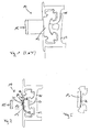
- the flap hinge assembly according to the invention is generally designated 10.
- the flap hinge assembly 10 is intended for use in the automotive or industrial sector, and in particular for several juxtaposed arranged flaps for storage space for z. As suitcases, luggage or other utensils.
- the flap hinge arrangement 10 according to the invention can also be provided for other types of flaps in the vehicle or industrial sector, for example in buses, small vehicles, rail vehicles, construction vehicles etc.
- the flaps are each in the region of a horizontally or vertically aligned longitudinal edge over the flap hinge assembly 10 at the Body hinged secured to make the respective storage space accessible in the unfolded state or to close in the closed state.
- flap hinge assembly 10 It includes the flap hinge assembly 10, see one of Figures 1 to 4 of the drawing, a body side fixed hinged 11 denoted hinge shell and a flap side fixed designated 12 hinge base and a flap movement enabling, with the hinge shell 11 and the hinge base 12 connected, with 13 designated hinge profile, in particular made of rubber.
- a flap hinge arrangement 10 is first shown.
- a flap hinge assembly 10 is a body side fixed hinge upper part 11 recognizable, a flap side attached hinge base 12 and the flap movement enabling, in a known manner via retaining lugs or cooperating undercuts with the hinge upper part 11 and the hinge base 12 connected hinge profile 13.
- the color of the externally marked by an optical viewing range of 15 in this case about 10 mm clearly visible hinge profile 13 is black, which greatly affects the appearance of the optical field of view 1 5 this type of flap hinge assemblies 10.
- the attempt to completely color the hinge profiles 13 failed, as described above, to a marked deterioration of the quality, in particular a deterioration in the elasticity of these hinge profiles 13. For this reason, additional cover elements for the visible region of these hinge profiles 13 were ultimately required for an optically continuous line, respectively the ugly appearance was to be accepted.
- the flap hinge assembly 10 means 14 for reducing the optical field of view 15 of the hinge profile 13 includes. 2, the means 14 for reducing the optical field of view 15 of the hinge profile 13 are formed, on the one hand, by a region-wise reduction of the rubber section in relation to the hinge profile 13 and by an extension 16 of the hinge upper part 11 on the other hand, the means 14 for reducing the optical field of view 15 of the hinge profile 13 by a in the optical field of view 15 of the hinge profile 13 arranged on this, in particular bead-like profile structure 17 are formed. It has in the illustrated in this Fig.
- the visible from the outside optical viewing area 15 of the hinge profile 13 can be reduced to about 6 mm, in particular by the region with respect to the hinge profile 13 reduction of the rubber section and by an extension of the hinge upper part 11, whereby an extension of the profile cover of the hinge profile 13 is achieved, and on the other hand supported by the in the optical field of view 1 5 of the hinge profile 13 arranged on this bead-like profile structure 17. It results from the inventive design not only a reduction of the optical field of view 15 itself, but it also results from this reduction of the optical field of view 15 better options for the optical adjustment of the remaining part of this optical field of vision 15th
- Another disadvantage of the known flap hinge assembly of FIG. 1 is that a retraction of the hinge profile 13 over the entire vehicle length z. B. an omnibus of about 10 m is not possible because it was practically impossible, in particular due to the friction coefficient from a length of about 4 to 5 m, the hinge profile 13 fit accurately in the hinge upper parts 11 and the hinge bottom parts 12. Therefore, in the known flap hinge arrangements 10, interrupted hinge profiles 13 were used, which in turn made additional strip elements or the like necessary for the optical covering of the interrupted points. In addition, it was problematic for a repair of individual flaps dismantling and reassembly of these individual flaps. It is therefore provided in the deviating from the Fig.
- hinge hinge assembly 10 according to Figures 3 and 4 of the drawing that the hinged to the hinge profile 13 in operative connection hinge part 11 is formed in two parts.
- this two-part hinge upper part 11 a retraction of the hinge profile 13 over the entire vehicle length is possible, with an optically over the entire vehicle length continuous hinge upper part 11 and hinge profile 13 is realized.
- the retraction of the hinge profile 13 in the hinge upper part 11 can be z. B. be made possible in such a way that the hinge upper part 11 is made with a first single element 20 and a second single element 21 in a slightly open state. It also eliminates the use of additional strip elements or the like.
- the two-part hinge top is also advantageous in terms of repair of individual flaps, as the disassembly and reassembly of individual flaps by solving the connection of the two-part hinge shell 11 and cutting and reinserting or reinserting parts of the hinge profile 13th can be done. It is the two-part hinge upper part 11 formed in the embodiments shown in Figures 3 and 4 of the drawing via a screw 22 composable.
- the screw connection 22 is arranged in the embodiment according to FIG. 3 of the drawing directly to the two individual elements 20 and 21 of the two-part hinge upper part 11.
- the two individual elements 20 and 21 of the two-part hinge upper part 11 each have in the area of the screw connection 22 a geometrically similar formed non-designated recess for receiving the screw thread on.
- an anti-theft device designated 27 is also shown on the hinge lower part, see also the embodiment according to FIG. 2 of the drawing.
- the screw connection 22 is arranged on web elements 23 and 24 provided separately for the two individual elements 20 and 21 of the two-part hinge upper part 11, wherein the geometric shape of these web elements 23 and 24 is such that an unsigned separate receiving space for the screw thread of the screw 22 results.
- the hinge profile 13 in its optical field of view 15 has a generally designated 25 colored design, which is located in this case on the located in the optical field of view 15 of the hinge profile 13 bead-like profile structure 17.
- this colored design 25 in the optical field of view 15 of the hinge profile 13 results in several, not shown separately in the figures of the drawing possibilities.
- the colored design 25 of the hinge profile 13 is formed in its optical viewing area 15 by a thin skin coextruded in this area.
- the colored design 25 of the hinge profile 13 is formed in its optical field of view 15 by a film lamination applied in this area, according to a third variant by a coating applied in this area and according to FIG a fourth variant by an applied in this area, for example via a roll liquid plastic.
- the hinge profile 13 is so connected to the hinge upper part 11 and the lower hinge part 12 of the flap hinge assembly 10, that for reducing the voltage of the hinge profile 13 of this hinge profile 13 in the resulting after production center position between open and the closed flap is in its substantially de-energized state. It results from this training on the one hand, a reduction in the voltage of the hinge profile 13 substantially in the open flap position, further improved sealing and a rattle-free seat is achieved by a distortion in the closed flap position. In addition, given by the reduction in stress in the hinge profile 13, the possibility to reduce this hinge profile 13. It is to FIG. 6 of the drawing for illustrative purposes, the representation according to FIG. 4 modified so that the hinge profile 13 is in its de-energized state.
- the hinge profile 13 inside a reinforcing insert 26 in this case comprises a textile insert.
- This arranged on the inside in the hinge profile textile insert 26 may be formed, for example, as a tissue, this training serves in particular a stabilization in the event of a tensile load, but the inner side arranged in the hinge profile 13 textile insert may also be formed as knitted fabric, in In this case, an elongation of the textile insert 26 is possible.
- the flap hinge arrangement 10 according to the invention compared to the known embodiments of flap hinge arrangements.
- the optical appearance of the flap hinge assembly 10 is improved in the optical field of view 15 of the hinge profile 13 without the use of additional cover elements by the flap hinge assembly 10 according to the invention.
- the possibility is created by the two-part design of the hinge upper part 11 to collect the hinge profiles over the entire vehicle length, d. H. to provide an optically over the entire vehicle length continuous hinge upper part 11 and hinge profile 13. Further advantages arise with regard to the colored design of the remaining optical field of view 15 of the hinge profile 13 and with respect to a reduction in the tension of this hinge profile 13.
- the illustrated embodiments are for example only implementations of the invention, this is not limited thereto, but rather many modifications and designs are possible.
- modifications to the execution of the hinge upper part 11 and the lower hinge part 12 and also of the hinge profile 13 are conceivable.
- modifications are provided, in particular with regard to the design of the means 14 for reducing the optical field of view 15 of the hinge profile 13.
Landscapes
- Engineering & Computer Science (AREA)
- Mechanical Engineering (AREA)
- Superstructure Of Vehicle (AREA)
- Closures For Containers (AREA)
- Hinges (AREA)
Priority Applications (1)
| Application Number | Priority Date | Filing Date | Title |
|---|---|---|---|
| PL04009774T PL1486635T3 (pl) | 2003-06-14 | 2004-04-24 | Układ zawiasu pokrywy |
Applications Claiming Priority (2)
| Application Number | Priority Date | Filing Date | Title |
|---|---|---|---|
| DE10326909A DE10326909B4 (de) | 2003-06-14 | 2003-06-14 | Klappenscharnieranordnung |
| DE10326909 | 2003-06-14 |
Publications (2)
| Publication Number | Publication Date |
|---|---|
| EP1486635A1 EP1486635A1 (de) | 2004-12-15 |
| EP1486635B1 true EP1486635B1 (de) | 2006-08-30 |
Family
ID=33185798
Family Applications (1)
| Application Number | Title | Priority Date | Filing Date |
|---|---|---|---|
| EP04009774A Expired - Lifetime EP1486635B1 (de) | 2003-06-14 | 2004-04-24 | Klappenscharnieranordnung |
Country Status (5)
| Country | Link |
|---|---|
| EP (1) | EP1486635B1 (pl) |
| AT (1) | ATE338186T1 (pl) |
| DE (2) | DE10326909B4 (pl) |
| ES (1) | ES2268531T3 (pl) |
| PL (1) | PL1486635T3 (pl) |
Family Cites Families (11)
| Publication number | Priority date | Publication date | Assignee | Title |
|---|---|---|---|---|
| DE1778933U (de) * | 1958-10-23 | 1958-12-04 | Daimler Benz Ag | Scharnierband aus elastischem kunststoff, bzw. aus gummi, fuer klappbare bauteile, insbesondere an wagenkaesten von kraftfahrzeugen. |
| US3032808A (en) * | 1959-11-10 | 1962-05-08 | Amerace Corp | Double-acting rubber hinge |
| GB1022636A (en) * | 1961-09-15 | 1966-03-16 | Casa Wolf S A | Plastic hinge |
| GB1329420A (en) * | 1971-07-30 | 1973-09-05 | Perfonit Ltd | Connections for panels |
| DE2239354C2 (de) * | 1972-08-10 | 1982-02-25 | Gebr. Happich Gmbh, 5600 Wuppertal | Scharnierleiste für die schwenkbewegliche Anordnung von Kofferraumdeckeln o.dgl. an der Fahrzeugkarosserie von Omnibussen |
| DE7301407U (de) * | 1973-01-16 | 1973-05-10 | Gebr Happich Gmbh | Scharnierleiste |
| DE7818170U1 (de) * | 1978-06-19 | 1978-10-05 | Gebr. Happich Gmbh, 5600 Wuppertal | Scharnierleiste |
| DE8011466U1 (de) * | 1980-04-26 | 1980-08-07 | Gebr. Happich Gmbh, 5600 Wuppertal | Scharnierleiste |
| DE3908256A1 (de) * | 1989-03-14 | 1990-09-20 | Walter Dipl Ing Feilhauer | Gelenk |
| DE4000500A1 (de) * | 1990-01-10 | 1990-07-26 | Kopp Franz Otto | Scharnierverbindung fuer platten, klappen, tuerblaetter und dergleichen |
| FR2736379B1 (fr) * | 1995-07-07 | 1998-01-23 | Alugrip | Dispositif d'articulation |
-
2003
- 2003-06-14 DE DE10326909A patent/DE10326909B4/de not_active Expired - Fee Related
-
2004
- 2004-04-24 EP EP04009774A patent/EP1486635B1/de not_active Expired - Lifetime
- 2004-04-24 DE DE502004001308T patent/DE502004001308D1/de not_active Expired - Lifetime
- 2004-04-24 PL PL04009774T patent/PL1486635T3/pl unknown
- 2004-04-24 ES ES04009774T patent/ES2268531T3/es not_active Expired - Lifetime
- 2004-04-24 AT AT04009774T patent/ATE338186T1/de not_active IP Right Cessation
Also Published As
| Publication number | Publication date |
|---|---|
| DE10326909A1 (de) | 2005-01-05 |
| DE10326909B4 (de) | 2005-04-28 |
| ES2268531T3 (es) | 2007-03-16 |
| ATE338186T1 (de) | 2006-09-15 |
| DE502004001308D1 (de) | 2006-10-12 |
| EP1486635A1 (de) | 2004-12-15 |
| PL1486635T3 (pl) | 2007-01-31 |
Similar Documents
| Publication | Publication Date | Title |
|---|---|---|
| EP0164532B2 (de) | Sonnendach für Fahrzeuge mit Strahlungsschutzblende | |
| DE102019128241A1 (de) | Türmodul mit rahmenloser glaskonfiguration mit einstellbaren glaslaufkanälen | |
| WO1988001950A1 (fr) | Toit decapotable pour voitures tout-terrain | |
| EP1974966A2 (de) | Kraftfahrzeug mit gegensinnig verschwenkbaren Seitentüren und einer zwischenliegenden Fahrzeugsäule | |
| DE69710564T2 (de) | Griff für öffnungsfähigen Flügel, und Schrank wovon die Tür mit einem derartigen Griff ausgerüstet ist | |
| DE102019107349A1 (de) | Trägermodul und Verfahren zum seitlichen Einbringen des Trägermoduls in eine Fahrzeugtür | |
| DE102009031686B4 (de) | Schubladenfront mit Verschließmechanismus zum Verriegeln von Schubladen in Fahrzeugen | |
| DE3904486C1 (en) | Deployable, transparent roof part for motor vehicles | |
| DE60022924T2 (de) | Innenteil einer Fahrzeugtür, korrespondierende Tür und Verfahren für den Zusammenbau einer solchen Tür | |
| DE60035756T2 (de) | Rollo, insbesondere für Autos, Schutzabdeckung und Montageverfahren hierzu | |
| DE4409420A1 (de) | Betätigungsvorrichtung für Handhaben von Türen und Fenstern | |
| EP1334857B1 (de) | Sonnenschutzbaugruppe für ein Fahrzeugdach | |
| DE102006021636B3 (de) | Schließvorrichtung | |
| EP1486635A1 (de) | Klappenscharnieranordnung | |
| CH688102A5 (de) | Falt- oder Schwingfluegeltor. | |
| DE4328886C2 (de) | Cabriolet mit einem Fondstauraum | |
| DE4430862A1 (de) | Kraftfahrzeugtür | |
| DE29722911U1 (de) | Kraftwagentüre | |
| EP2692565B1 (de) | Windschottvorrichtung für Cabriolet-PKW | |
| DE19912077C2 (de) | Außentür für einen Wohnwagen, ein Wohnmobil oder dgl. | |
| DE102004025075B4 (de) | Anordnung mit einer Faltdrehtür und Faltdrehtür | |
| DE4403524A1 (de) | Anordnung eines Ecklagers an einem Fenster oder einer Tür sowie für diese Anordnung bestimmtes Ecklager | |
| DE3333215A1 (de) | Windabweiser | |
| DE20110090U1 (de) | Schrank wie Gefahrstoffschrank | |
| DE29916376U1 (de) | Türbeschlag |
Legal Events
| Date | Code | Title | Description |
|---|---|---|---|
| PUAI | Public reference made under article 153(3) epc to a published international application that has entered the european phase |
Free format text: ORIGINAL CODE: 0009012 |
|
| 17P | Request for examination filed |
Effective date: 20041012 |
|
| AK | Designated contracting states |
Kind code of ref document: A1 Designated state(s): AT BE BG CH CY CZ DE DK EE ES FI FR GB GR HU IE IT LI LU MC NL PL PT RO SE SI SK TR |
|
| AX | Request for extension of the european patent |
Extension state: AL HR LT LV MK |
|
| AKX | Designation fees paid |
Designated state(s): AT BE BG CH CY CZ DE DK EE ES FI FR GB GR HU IE IT LI LU MC NL PL PT RO SE SI SK TR |
|
| GRAP | Despatch of communication of intention to grant a patent |
Free format text: ORIGINAL CODE: EPIDOSNIGR1 |
|
| GRAS | Grant fee paid |
Free format text: ORIGINAL CODE: EPIDOSNIGR3 |
|
| GRAA | (expected) grant |
Free format text: ORIGINAL CODE: 0009210 |
|
| AK | Designated contracting states |
Kind code of ref document: B1 Designated state(s): AT BE BG CH CY CZ DE DK EE ES FI FR GB GR HU IE IT LI LU MC NL PL PT RO SE SI SK TR |
|
| PG25 | Lapsed in a contracting state [announced via postgrant information from national office to epo] |
Ref country code: IT Free format text: LAPSE BECAUSE OF FAILURE TO SUBMIT A TRANSLATION OF THE DESCRIPTION OR TO PAY THE FEE WITHIN THE PRESCRIBED TIME-LIMIT;WARNING: LAPSES OF ITALIAN PATENTS WITH EFFECTIVE DATE BEFORE 2007 MAY HAVE OCCURRED AT ANY TIME BEFORE 2007. THE CORRECT EFFECTIVE DATE MAY BE DIFFERENT FROM THE ONE RECORDED. Effective date: 20060830 Ref country code: CZ Free format text: LAPSE BECAUSE OF FAILURE TO SUBMIT A TRANSLATION OF THE DESCRIPTION OR TO PAY THE FEE WITHIN THE PRESCRIBED TIME-LIMIT Effective date: 20060830 Ref country code: GB Free format text: LAPSE BECAUSE OF FAILURE TO SUBMIT A TRANSLATION OF THE DESCRIPTION OR TO PAY THE FEE WITHIN THE PRESCRIBED TIME-LIMIT Effective date: 20060830 Ref country code: FI Free format text: LAPSE BECAUSE OF FAILURE TO SUBMIT A TRANSLATION OF THE DESCRIPTION OR TO PAY THE FEE WITHIN THE PRESCRIBED TIME-LIMIT Effective date: 20060830 Ref country code: RO Free format text: LAPSE BECAUSE OF FAILURE TO SUBMIT A TRANSLATION OF THE DESCRIPTION OR TO PAY THE FEE WITHIN THE PRESCRIBED TIME-LIMIT Effective date: 20060830 Ref country code: SK Free format text: LAPSE BECAUSE OF FAILURE TO SUBMIT A TRANSLATION OF THE DESCRIPTION OR TO PAY THE FEE WITHIN THE PRESCRIBED TIME-LIMIT Effective date: 20060830 Ref country code: SI Free format text: LAPSE BECAUSE OF FAILURE TO SUBMIT A TRANSLATION OF THE DESCRIPTION OR TO PAY THE FEE WITHIN THE PRESCRIBED TIME-LIMIT Effective date: 20060830 Ref country code: IE Free format text: LAPSE BECAUSE OF FAILURE TO SUBMIT A TRANSLATION OF THE DESCRIPTION OR TO PAY THE FEE WITHIN THE PRESCRIBED TIME-LIMIT Effective date: 20060830 |
|
| REG | Reference to a national code |
Ref country code: GB Ref legal event code: FG4D Free format text: NOT ENGLISH |
|
| REG | Reference to a national code |
Ref country code: CH Ref legal event code: EP |
|
| REG | Reference to a national code |
Ref country code: IE Ref legal event code: FG4D Free format text: LANGUAGE OF EP DOCUMENT: GERMAN |
|
| REF | Corresponds to: |
Ref document number: 502004001308 Country of ref document: DE Date of ref document: 20061012 Kind code of ref document: P |
|
| PG25 | Lapsed in a contracting state [announced via postgrant information from national office to epo] |
Ref country code: SE Free format text: LAPSE BECAUSE OF FAILURE TO SUBMIT A TRANSLATION OF THE DESCRIPTION OR TO PAY THE FEE WITHIN THE PRESCRIBED TIME-LIMIT Effective date: 20061130 Ref country code: DK Free format text: LAPSE BECAUSE OF FAILURE TO SUBMIT A TRANSLATION OF THE DESCRIPTION OR TO PAY THE FEE WITHIN THE PRESCRIBED TIME-LIMIT Effective date: 20061130 Ref country code: BG Free format text: LAPSE BECAUSE OF FAILURE TO SUBMIT A TRANSLATION OF THE DESCRIPTION OR TO PAY THE FEE WITHIN THE PRESCRIBED TIME-LIMIT Effective date: 20061130 |
|
| REG | Reference to a national code |
Ref country code: PL Ref legal event code: T3 |
|
| PG25 | Lapsed in a contracting state [announced via postgrant information from national office to epo] |
Ref country code: PT Free format text: LAPSE BECAUSE OF FAILURE TO SUBMIT A TRANSLATION OF THE DESCRIPTION OR TO PAY THE FEE WITHIN THE PRESCRIBED TIME-LIMIT Effective date: 20070212 |
|
| ET | Fr: translation filed | ||
| REG | Reference to a national code |
Ref country code: HU Ref legal event code: AG4A Ref document number: E001038 Country of ref document: HU |
|
| REG | Reference to a national code |
Ref country code: ES Ref legal event code: FG2A Ref document number: 2268531 Country of ref document: ES Kind code of ref document: T3 |
|
| GBV | Gb: ep patent (uk) treated as always having been void in accordance with gb section 77(7)/1977 [no translation filed] |
Effective date: 20060830 |
|
| REG | Reference to a national code |
Ref country code: IE Ref legal event code: FD4D |
|
| PLBE | No opposition filed within time limit |
Free format text: ORIGINAL CODE: 0009261 |
|
| STAA | Information on the status of an ep patent application or granted ep patent |
Free format text: STATUS: NO OPPOSITION FILED WITHIN TIME LIMIT |
|
| 26N | No opposition filed |
Effective date: 20070531 |
|
| PG25 | Lapsed in a contracting state [announced via postgrant information from national office to epo] |
Ref country code: GR Free format text: LAPSE BECAUSE OF FAILURE TO SUBMIT A TRANSLATION OF THE DESCRIPTION OR TO PAY THE FEE WITHIN THE PRESCRIBED TIME-LIMIT Effective date: 20061201 |
|
| PG25 | Lapsed in a contracting state [announced via postgrant information from national office to epo] |
Ref country code: EE Free format text: LAPSE BECAUSE OF FAILURE TO SUBMIT A TRANSLATION OF THE DESCRIPTION OR TO PAY THE FEE WITHIN THE PRESCRIBED TIME-LIMIT Effective date: 20060830 |
|
| PG25 | Lapsed in a contracting state [announced via postgrant information from national office to epo] |
Ref country code: AT Free format text: LAPSE BECAUSE OF NON-PAYMENT OF DUE FEES Effective date: 20070424 |
|
| PGRI | Patent reinstated in contracting state [announced from national office to epo] |
Ref country code: IT Effective date: 20080601 |
|
| REG | Reference to a national code |
Ref country code: CH Ref legal event code: PL |
|
| PG25 | Lapsed in a contracting state [announced via postgrant information from national office to epo] |
Ref country code: CH Free format text: LAPSE BECAUSE OF NON-PAYMENT OF DUE FEES Effective date: 20080430 Ref country code: LI Free format text: LAPSE BECAUSE OF NON-PAYMENT OF DUE FEES Effective date: 20080430 |
|
| PG25 | Lapsed in a contracting state [announced via postgrant information from national office to epo] |
Ref country code: MC Free format text: LAPSE BECAUSE OF NON-PAYMENT OF DUE FEES Effective date: 20070430 |
|
| PG25 | Lapsed in a contracting state [announced via postgrant information from national office to epo] |
Ref country code: LU Free format text: LAPSE BECAUSE OF NON-PAYMENT OF DUE FEES Effective date: 20070424 Ref country code: CY Free format text: LAPSE BECAUSE OF FAILURE TO SUBMIT A TRANSLATION OF THE DESCRIPTION OR TO PAY THE FEE WITHIN THE PRESCRIBED TIME-LIMIT Effective date: 20060830 |
|
| PGFP | Annual fee paid to national office [announced via postgrant information from national office to epo] |
Ref country code: TR Payment date: 20110414 Year of fee payment: 8 Ref country code: FR Payment date: 20110510 Year of fee payment: 8 Ref country code: ES Payment date: 20110418 Year of fee payment: 8 Ref country code: DE Payment date: 20110426 Year of fee payment: 8 |
|
| PGFP | Annual fee paid to national office [announced via postgrant information from national office to epo] |
Ref country code: PL Payment date: 20110413 Year of fee payment: 8 Ref country code: HU Payment date: 20110509 Year of fee payment: 8 Ref country code: NL Payment date: 20110426 Year of fee payment: 8 Ref country code: BE Payment date: 20110414 Year of fee payment: 8 |
|
| PGFP | Annual fee paid to national office [announced via postgrant information from national office to epo] |
Ref country code: IT Payment date: 20110430 Year of fee payment: 8 |
|
| REG | Reference to a national code |
Ref country code: DE Ref legal event code: R081 Ref document number: 502004001308 Country of ref document: DE Owner name: HAPPICH GMBH, DE Free format text: FORMER OWNER: HAPPICH FAHRZEUG- UND INDUSTRIETEILE GMBH, 42285 WUPPERTAL, DE Effective date: 20111220 Ref country code: DE Ref legal event code: R081 Ref document number: 502004001308 Country of ref document: DE Owner name: HAPPICH GMBH, DE Free format text: FORMER OWNER: HAPPICH GMBH, 42119 WUPPERTAL, DE Effective date: 20120127 |
|
| BERE | Be: lapsed |
Owner name: *HAPPICH FAHRZEUG- UND INDUSTRIETEILE G.M.B.H. Effective date: 20120430 |
|
| REG | Reference to a national code |
Ref country code: NL Ref legal event code: V1 Effective date: 20121101 |
|
| REG | Reference to a national code |
Ref country code: FR Ref legal event code: ST Effective date: 20121228 |
|
| PG25 | Lapsed in a contracting state [announced via postgrant information from national office to epo] |
Ref country code: HU Free format text: LAPSE BECAUSE OF NON-PAYMENT OF DUE FEES Effective date: 20120425 Ref country code: BE Free format text: LAPSE BECAUSE OF NON-PAYMENT OF DUE FEES Effective date: 20120430 |
|
| REG | Reference to a national code |
Ref country code: DE Ref legal event code: R119 Ref document number: 502004001308 Country of ref document: DE Effective date: 20121101 |
|
| PG25 | Lapsed in a contracting state [announced via postgrant information from national office to epo] |
Ref country code: FR Free format text: LAPSE BECAUSE OF NON-PAYMENT OF DUE FEES Effective date: 20120430 Ref country code: IT Free format text: LAPSE BECAUSE OF FAILURE TO SUBMIT A TRANSLATION OF THE DESCRIPTION OR TO PAY THE FEE WITHIN THE PRESCRIBED TIME-LIMIT Effective date: 20120424 |
|
| PG25 | Lapsed in a contracting state [announced via postgrant information from national office to epo] |
Ref country code: NL Free format text: LAPSE BECAUSE OF NON-PAYMENT OF DUE FEES Effective date: 20121101 |
|
| REG | Reference to a national code |
Ref country code: ES Ref legal event code: FD2A Effective date: 20130715 |
|
| PG25 | Lapsed in a contracting state [announced via postgrant information from national office to epo] |
Ref country code: ES Free format text: LAPSE BECAUSE OF NON-PAYMENT OF DUE FEES Effective date: 20120425 |
|
| REG | Reference to a national code |
Ref country code: PL Ref legal event code: LAPE |
|
| PG25 | Lapsed in a contracting state [announced via postgrant information from national office to epo] |
Ref country code: PL Free format text: LAPSE BECAUSE OF NON-PAYMENT OF DUE FEES Effective date: 20120424 |
|
| PG25 | Lapsed in a contracting state [announced via postgrant information from national office to epo] |
Ref country code: TR Free format text: LAPSE BECAUSE OF NON-PAYMENT OF DUE FEES Effective date: 20120424 |
|
| PG25 | Lapsed in a contracting state [announced via postgrant information from national office to epo] |
Ref country code: DE Free format text: LAPSE BECAUSE OF NON-PAYMENT OF DUE FEES Effective date: 20121101 |