EP1486597A2 - Procédé et dispositif de commande de la formation de la foule de métier à tisser - Google Patents
Procédé et dispositif de commande de la formation de la foule de métier à tisser Download PDFInfo
- Publication number
- EP1486597A2 EP1486597A2 EP04011310A EP04011310A EP1486597A2 EP 1486597 A2 EP1486597 A2 EP 1486597A2 EP 04011310 A EP04011310 A EP 04011310A EP 04011310 A EP04011310 A EP 04011310A EP 1486597 A2 EP1486597 A2 EP 1486597A2
- Authority
- EP
- European Patent Office
- Prior art keywords
- rotational
- heald frame
- section
- rotational speed
- eccentric portion
- Prior art date
- Legal status (The legal status is an assumption and is not a legal conclusion. Google has not performed a legal analysis and makes no representation as to the accuracy of the status listed.)
- Granted
Links
Images


Classifications
-
- D—TEXTILES; PAPER
- D03—WEAVING
- D03C—SHEDDING MECHANISMS; PATTERN CARDS OR CHAINS; PUNCHING OF CARDS; DESIGNING PATTERNS
- D03C13/00—Shedding mechanisms not otherwise provided for
-
- D—TEXTILES; PAPER
- D03—WEAVING
- D03C—SHEDDING MECHANISMS; PATTERN CARDS OR CHAINS; PUNCHING OF CARDS; DESIGNING PATTERNS
- D03C13/00—Shedding mechanisms not otherwise provided for
- D03C13/02—Shedding mechanisms not otherwise provided for with independent drive motors
- D03C13/025—Shedding mechanisms not otherwise provided for with independent drive motors with independent frame drives
Definitions
- the present invention relates to a shedding control method and device of a shedding device forming a warp shedding in a loom.
- back and forth direction means the moving direction of the warp by warp let-off
- vertical direction the moving direction of a heald frame.
- Front side and rear side respectively mean the downstream side and upstream side in the moving direction of the warp;
- left” and “right” respectively mean leftward and rightward as viewed from the downstream side in the moving direction of the warp.
- Upper limit position and “lower limit position” respectively mean the positions where the heald frame is located at the upper limit and lower limit in the range of the vertical motion of the heald frame.
- “Geometrical intermediate position” means the geometrical middle position between the upper limit and lower limit positions of the heald frame.
- each heald frame is vertically moved through a power converting mechanism provided with a gear having an eccentric portion to be rotated in one direction by an electric motor for heald frame in each heald frame.
- This shedding device has a quadric link comprising a swing lever, a connection rod and a gear acting as a crank, for converting so-called rotational motion into reciprocal motion.
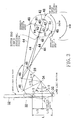
- a quadric link for converting rotational motion to reciprocal motion converts, as shown in Fig. 3, rotational motion of a pivot (a pin shaft 48 in Fig. 3) which rotates about an output shaft (output shaft 40 in Fig. 3) of a rotary drive source into reciprocal motion of a swing lever (swing lever 28 in Fig. 3) supported so as to swing about a support shaft (support shaft 34 in Fig. 3) through a connection member (connection member 44 in Fig. 3).
- the foregoing shedding device detects a moving amount of a vertically moved heald frame by a sensor, compares the detected moving amount with an ideal moving amount of the heald frame, and correct a phase angle of the heald frame for a predetermined period from after starting of operation of a loom so as to coincide with a preset shedding curve.
- one and another rotational positions of the pin shaft 48 when the heald frame is at a geometrical intermediate position is, as evident from Fig. 3, not at a point-symmetrical position with an output shaft 40 as the center.
- the first and second heald frame groups moving in the vertical direction has cross points P at positions different from the geometrical intermediate position.
- An object of the present invention lies in setting the cross points P of the heald frame groups at the geometrical intermediate position and improving the weaving property.
- the shedding control method and device according to the present invention is applied to controlling a shedding device, of a loom, which vertically moves each of heald frames through a crank mechanism having an eccentric portion to be rotated in one direction by a motor for heald frame provided in each heald frame.
- the shedding control method comprises: rotating the eccentric portion at a first rotational speed in a first section between an intermediate rotational position of the eccentric portion corresponding to when the heald frame is located at an intermediate position between an upper limit position and a lower limit position and a top dead center rotational position of the eccentric portion corresponding to when the heald frame is located at the upper limit position; and rotating the eccentric portion at a second rotational speed different from the first rotational speed in a second section between a bottom dead center rotational position of the eccentric portion corresponding to when the heald frame is located at a lower limit position and the intermediate rotational position.
- a relation in magnitude of the first and second rotational speeds is made to correspond to a relation in dimension of the first and second sections.
- the shedding control device comprises a control portion which rotates the eccentric portion at a first rotational speed in a first section between an intermediate rotational position of the eccentric portion corresponding to when the heald frame is located at an intermediate position between the upper limit position and the lower limit position and the top dead center rotational position corresponding to when the heald frame is located at the upper limit position, and which rotates at a second rotational speed different from the first rotational speed in a second section between the bottom dead center rotational position of the eccentric portion corresponding to when the heald frame is located at the lower limit position and the intermediate rotational position.
- the control portion makes the relation in magnitude of the first rotational speed and the second rotational speed correspond to the relation in dimension of the first section and the second section.
- the dimension of section means an angular size of a section, that is, the angle of the section, and means a rotational angle required for the eccentric portion to move in the section, that is, a required amount of rotation of the eccentric portion in the section.
- the eccentric portion is rotated at a higher speed in a large section than a small section. This makes the cross point of the heald frame and a so-called reverse shedding frame which is moved in the opposite direction thereto approaches the geometrical intermediate position, thereby improving the weaving property of the loom.
- the ratio of an average rotational speed of the first rotational speed and an average rotational speed of the second rotational speed may be made to correspond to the ratio in dimension of the first section and the second section.
- the rotational speed of the motor for heald frame in the first section and that in the second section may be set for each heald frame.
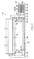
- the shedding device 10 is used as a device for forming a warp shedding by reciprocating in the vertical direction a plurality of heald frames 18 arranged at intervals in the back and forth direction between right and left frames (posts) 14 and 16 of a loom 12 together with healds disposed therein.
- frames 14, 16 are connected by an upper and a lower frames (beams) 20 and supported so as to move in the vertical direction through a support member not shown in the frames 14, 16, 20.
- a plurality of heald frmes 18 are divided into a first and a second heald frame groups each including a plurality of heald frames 18.
- the first and second heald frame groups have such a relation as to be shifted in phase by 180° in a rotational angle of the main shaft relative to each other to be vertically moved so that when one is moved upward, the other may be moved downward.
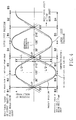
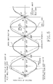
- the first and second heald frame groups intersect at the cross points P as shown in solid lines in Fig. 4 or 5, and the warp shedding amount becomes zero.
- the shedding device 10 comprises a plurality of support mechanisms 22 provided in each heald frame 18 and supporting the corresponding heald frame 18 so as to move vertically, and a plurality of drive mechanisms made to correspond individually to the support mechanisms 22.
- the support mechanisms 22 are divided into a first and a second support mechanism groups according to the group to which the corresponding heald frames 18 belong.
- the drive mechanisms are divided into a first and a second drive mechanism groups 24 and 26 according to the group to which the corresponding heald frames and the support mechanisms 22 belong.
- the support mechanisms 22 of the first support mechanism group are made to correspond individually to the heald frames 18 of the first heald frame group and the drive mechanisms of the first drive mechanism group 24, and are driven by the corresponding drive mechanisms and move the corresponding heald frames 18 in the vertical direction.
- the support mechanisms 22 of the second support mechanism group are made to correspond individually to the heald frames 18 of the second heald frame group and the drive mechanisms of the second drive mechanism group 26, are driven by the corresponding drive mechanisms and move the corresponding heald frames 18 in the vertical direction.
- Each support mechanism 22 is a known mechanism which connects a pair of right and left swing levers 28 having a V-letter or a Y-letter shape by a link 30 extending in the rightward and leftward direction and which connects each swing lever 28 on the right and left of the corresponding heald frame 18 by a connection rod 32 which extends vertically.
- the swing lever 28 on the left side has a V-letter shape
- the swing lever 28 on the right side has a Y-letter shape.
- Both swing levers 28 are pivotally connected at one of the tips of the V-letter shape or Y-letter shape to the link 30, and pivotally connected at another tip to the connection rod 32.
- the swing levers 28, 28 on the right and left sides are supported pivotally at the base portions, that is, the branch connections of the V-letter shape and Y-letter shape by common support shafts 34, 34 on the right and left sides in each right and left swing lever groups so as to swing within a plane extending in the vertical direction as well as in the rightward and leftward direction.
- the right and left support shafts 34 and 34 extend in the back and forth direction between the frames 14 and 16 and are supported on the right frame 16 and the lower frame 20 respectively through a bracket. Consequently, the plural swing levers 28, 28 are pivotally supported on a base through the right and left support shafts 34, 34.
- connection rod 32 is a member with one end of its screw rod screwed into a threaded hole of a long female screw body.
- the connection rod 32 is disposed to extend vertically, pivotally connected at its upper end to the heald frames 18, and pivotally connected at its lower end to the swing lever 28.
- Each drive mechanism of the drive mechanism groups 24, 26 includes: a drive source, i.e., an electric motor 38, such as a servo motor assembled into the right frame 16 by the bracket 36 such that the rotation axis extends in the back and forth direction; an eccentric joint 42 assembled into the output shaft 40 of the electric motor 38; and long connection members 44 pivotally connected at one end to the eccentric joint 42.
- a drive source i.e., an electric motor 38, such as a servo motor assembled into the right frame 16 by the bracket 36 such that the rotation axis extends in the back and forth direction
- an eccentric joint 42 assembled into the output shaft 40 of the electric motor 38
- long connection members 44 pivotally connected at one end to the eccentric joint 42.
- connection member 44 which is a long plate-like member, is connected at the other end to the corresponding remaining tip of the Y-letter shape of the right swing lever 28 through an arm member 50, which supports a pivot 46, and connected by the pivot 46 so as to swing within a plane extending in the vertical direction as well as in the rightward and leftward direction.
- the arm member 50 is attached to the swing lever 28 with a bolt, and the distance from the support shaft 34 to the arm member 50 can be adjusted. By adjusting the distance from the support shaft 34 to the arm member 50, the swinging angle of the swing lever 28 is changed, and the amount of motion (shedding amount) of the heald frame 18 is adjusted.
- Each eccentric joint 42 has a disk-like shape as viewed in the back and forth direction.
- a fitting hole (not shown) of each eccentric joint 42 is fitted with the output shaft 40 so as not to rotate relatively.
- Each eccentric joint 42 has a pin shaft 48 at an eccentric position relative to the output shaft 40, and assembles the one end portion of the connection member 44 swingably by the pin shaft 48.
- the pin shaft 48 is rotated around the rotation axis of the output shaft 40 in an eccentric state relative to the output shaft 40.
- crank mechanism having an eccentric portion (pin shaft 48) which is eccentric to the output shaft 40 is constituted.
- This crank mechanism acts as a motion converting mechanism for converting a rotational motion of the electric motor 38 into a reciprocal motion of the connecting member 44.
- the axes of the pivot connecting the heald frame 18 and the connection rod 32, the pivot connecting the connection rod 32 and the swing lever 28, the pivot connecting the swing lever 28 and the link 30, and the pivot 46 connecting the swing lever 28 and the connection member 44 all extend in the back and forth direction.
- the electric motors 38 of the first and second drive mechanism groups 24 and 26 are assembled into the bracket 36 such that the output shaft 40 extends in the back and forth direction, and arranged in the upward and downward direction and the rightward and leftward direction.
- Each electric motor 38 is connected to the corresponding support mechanisms 22 through the eccentric joint 42 and connection member 44.
- Each electric motor 38 is set in one of the rotational directions, that is, either clockwise (cw direction in Fig. 3) or counterclockwise (ccw direction in Fig. 3) as viewed from the downstream side in the moving direction of the warp. In this embodiment, it is set in the counterclockwise rotation.
- a shedding control device 52 includes a servo amplifier 56 for driving the electric motor 38, and an encoder 58 for detecting the rotation angle of the output shaft 40 of each electric motor 38.
- a main control device 60 of the loom 12 outputs a main shaft rotation signal S2 such as operation, stop, inching, etc., to a main shaft motor 64.
- the main shaft motor 64 rotates a main shaft 66 according to the main shaft rotation signal S2.
- An encoder 68 detects and outputs a rotational angle ⁇ of the main shaft 66 to the main control device 60 and a shedding control circuit 70 as a main shaft rotational angle signal S3.
- Operation setting values such as a setting value like the rotational frequency of the loom, and shedding setting values such as shedding pattern, shedding amount, dwell amount, the rotational angle of the main shaft 66 at a cross point P are inputted to a loom input/output device 62 by an operator.
- the loom input/output device 62 outputs such information (setting value) respectively to the main control device 60 and the shedding control circuit 70 as an operation setting signal S1 and a shedding setting signal S6.
- a required amount of rotation for the output shaft 40 in each of section (B1, B2, B3, and B4) divided into four in Fig. 3 is previously measured and inputted in correspondence to the shedding amount of each heald frame 18.
- the shedding control circuit 70 operates for each heald frame 18, a rotational speed of the servo motor 38 in each section (B1, B2, B3 and B4) on the basis of information of the shedding setting signal S6, such as shedding pattern, shedding amount, dwell amount, rotational angle of the main shaft 66 at the cross point P, and outputs the rotational speed to the servo amplifier 56 as a heald frame drive signal S51, ..., S5i, ..., or S5n (i: frame No.) on the basis of a main shaft rotational angle signal S3 from the encoder 68.
- Each servo amplifier 56 drives the electric motor 38 for the heald frame on the basis of the heald frame drive signal S51, ..., S5i, ..., or S5n and moves the heald frame 18 vertically.
- Each encoder 58 detects the rotational angle of the output shaft 40 of the corresponding electric motor 38 and outputs the detected rotational angle to the shedding control circuit 70 as a motor rotational angle signal S71, ..., S7i, ..., or S7n.
- the shedding control circuit 70 controls the position of the electric motor 38 by feedback control. More concretely, on the basis of the main shaft rotational angle signal S3, the shedding control circuit 70 obtains a deviation of the rotational angle of the output shaft 40 and its target value from the motor rotational angle signal S7, and accelerates or decelerates the rotational speed of the electric motor 38 in the direction for dissolving the deviation.
- the shedding control circuit 70 outputs to the servo amplifier 56 (in turn, the electric motor 38) the heald frame drive signal S51, ..., S5i, ..., or S5n for the output shaft 40 of the electric motor 38 to make one turn while the main shaft 66 makes two turns.
- the center of the vertical moving distance L of the heald frame 18 in the vertical direction is adapted to be a geometrical intermediate position of the heald frame (see Figs. 3 and 4).
- the rotational angles of the swing lever 28 from the upper limit position of the heald frame 18 to the geometrical intermediate position and from the geometrical intermediate position to the lower limit position are respectively made approximately half the rotational angle ⁇ from the upper limit position to the lower limit position.
- the rotational positions of the pin shaft 48 which is an eccentric portion, when the heald frame 18 moves to the upper limit position, the geometrical intermediate position, the lower limit position and the geometrical intermediate position in order are respectively made a top dead center rotational position (point), an intermediate rotational position (point) in descent, a bottom dead center rotational position (point) and an intermediate rotational position (point) in ascent.
- the range of rotation of the output shaft 40 can be divided into sections B1, B2, B3 and B4 on the basis of the bottom dead center, the intermediate rotational position in ascent, the top dead center rotational position and the intermediate rotational position in descent respectively of the pin shaft 48.
- the section B1 shows the distance from the rotational position (bottom dead center rotational position) of the pin shaft 48 corresponding to when the heald frame 18 is located at the lower limit position to the rotational position (the intermediate rotational position in ascent) of the pin shaft 48 corresponding to when the heald frame 18 is located at the geometrical intermediate position).
- the section B2 shows the distance from the rotational position (the intermediate rotational position in ascent) of the pin shaft 48 corresponding to when the heald frame 18 is located at the geometrical intermediate position to the rotational position (the top dead center rotational position) of the pin shaft 48 corresponding to when the heald frame 18 is located at the upper limit position.
- the section B3 shows the distance from the rotational position (the top dead center rotational position) of the pin shaft 48 corresponding to when the heald frame 18 is located at the upper limit position to the rotational position (the intermediate rotational position in descent) of the pin shaft 48 corresponding to when the heald frame 18 is located at the geometrical intermediate rotational position.
- the section B4 shows the distance from the rotational position (the intermediate rotational position in descent) of the pin shaft 48 corresponding to when the heald frame 18 is located at the geometrical intermediate position to the rotational position (the bottom dead center rotational position) of the pin shaft 48 corresponding to when the heald frame 18 is located at the lower limit position.
- the shedding control circuit 70 is set so that the rotational speed may be accelerated in a section where the predetermined rotational amount of the pin shaft 48 is great, and that the rotational speed may be reduced in a section where the predetermined rotation amount of the pin shaft 48 is small.
- m represents a section No. (1 to 4)
- ⁇ m represents an angle (°) of the output shaft 40 in the section Bm, i.e., the required rotational amount of the pin shaft 48 as the eccentric portion
- ⁇ m represents the required rotational angle (in this embodiment, both 180°) of the main shaft 66 corresponding to the section Bm
- am represents the ratio of rotational speeds of the output shaft 40 corresponding to the rotational speed of the main shaft 66 in the section Bm.
- the ratio am of rotational speeds means rotating the output shaft 40 at a speed am times the rotational speed of the main shaft 66.
- the shedding control circuit 70 outputs a heald frame drive signal S5i which is 0.583 times and 0.417 times the rotational speed of the main shaft 66 in the sections B2 and B4 and drives the servo motor 38.
- the sections B1 and B3 can be also obtained in the same manner as the above-mentioned steps.
- the required rotational amounts of the pin shaft 48 are the same in the sections B1 and B3 as well as in the sections B2 and B4, but differ depending on the frame Nos.
- the ratio of rotational speeds in respective sections of the servo motor 38 is set at the ratio of a predetermined rotational amounts in respective sections of the pin shaft 48 through the rotational speed of the main shaft 66.
- the required time between the upper limit position and the geometrical intermediate position and the required time between the lower limit position and the geometrical intermediate position become the same, and those required times coincide with the required time of a half turn of the main shaft. Consequently, each heald frame 18 reaches the geometrical intermediate position at each half turn of the main shaft 66.
- the heald frame 18 for reverse shedding to this heald frame 18 is also set likewise. Consequently, since each heald frame 18 reaches the geometrical intermediate position at every half turn of the main shaft 66, the crosspoint P of the heald frames having sheddings reverse to each other is located at the geometrical intermediate position.
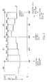
- Figs. 4 and 5 are curves of movement of one heald frame 18 of the first heald frame group and one heald frame 18 of the second heald frame group.
- the solid lines shown in Figs. 4 and 5 are based on this embodiment.
- both comparative example 1 of the two-dot chain lines shown in Fig. 4 and comparative example 2 of the two-dot chain lines shown in Fig. 5 relate to conventional arts.
- the rotational speeds of the servo motors in comparative examples 1 and 2 are not changeable at respective sections, namely, to be the same, so that the crosspoint P is not located in the geometrical intermediate position or changes constantly.
- the heald frame drive signal S5 includes a pulse, and the electric motor (servo motor) 38 is controlled by a pulse fed from the shedding control circuit 70 to the servo amplifier 56.
- q shows the rotational angle (°/pulse) of the output shaft 40 per one pulse, and is set at 0.4 in this embodiment.
- ⁇ shows a unit rotational amount of the main shaft 66. In other words, when the main shaft 66 rotates by the rotational angle ⁇ (°), a predetermined number of pulses are generated.
- the shedding control circuit 70 outputs the heald frame drive signal S5i while the main shaft 66 rotates in the ranges of rotation A2 and A4 of the main shaft 66 corresponding to sections B2 and B4 every time the rotational angle ⁇ advances by 15°.
- the rotational speed preset in the shedding control circuit 70 may be computed in the shedding control circuit 70 or may be operated in the loom input and output device 62.
- Section A1 (the required rotational amount of the main shaft 66 is ⁇ 1) of the main shaft 66 corresponding to sections B1 and B2 and section A2 (the required rotational amount of the main shaft 66 is ⁇ 2) are respectively divided uniformly into k pieces of small sections A11, ..., A1j, ..., A1k and small sections A21, ..., A2j, ..., A2k.
- the required rotational amounts of the main shaft 66 in the small section of sections A1 and A2 respectively become ⁇ 1/k and ⁇ 2/k.
- Sections B1 and B2 are also divided into small sections B11, ..., B1j, ..., B1k and B21, ..., B2j, ..., B2k in correspondence to small sections A11, ..., A1j, ..., A1k and small sections A21, ..., A2j, ..., A2k of sections A1 and A2.
- the rotational angle ⁇ 1 in section B1 and the rotational angles ⁇ 11, ..., ⁇ 1j, ..., ⁇ 1k of small sections B11, ..., B1j, ..., B1k have a relation as shown in Formula (4).
- ⁇ 1 ⁇ 11 + ⁇ 12 + ... + ⁇ 1j + ... + ⁇ 1k
- ⁇ 1 shows the required rotational angle of the output shaft 40 in section B1
- ⁇ 11, ⁇ 12, ..., ⁇ 1j, ..., ⁇ 1k show the required rotational angles of the output shaft 40 corresponding to small sections B11, ..., B1j, ..., B1k which are obtained by dividing section B1 into k pieces.
- the rotational speed of the output shaft 40 in the corresponding small section B1j (the required rotational amount of the output shaft 40 is ⁇ 1j) has the value in the following Formula (5) relative to a unit angle (i.e., 1°) of the main shaft 66. ⁇ 1j/( ⁇ 1/k)
- the ratio of the required rotational amounts of corresponding small sections is made coincident with the ratio of the required rotational amounts of sections B1 and B2, it may be increased or decreased in the required rotational amounts corresponding some part of small sections. Consequently, the rotational angle ⁇ 2 of the output shaft 40 in section B2 can be expanded into the rotational angles ⁇ 21, ⁇ 22, ..., ⁇ 2j, ..., ⁇ 2k of the output shaft 40 corresponding to small sections B21, B22, ..., B2j, ..., B2k, as shown in Formula (6).
- ⁇ 2 ( ⁇ 2/ ⁇ 1) ⁇ 11 + ( ⁇ 2/ ⁇ 1)( ⁇ 12 + ... + ( ⁇ 2/ ⁇ 1) ⁇ 1j + ... + ( ⁇ 2/ ⁇ 1) ⁇ 1k
- the rotational speed of the output shaft 40 in small section B2j (the required rotational amount of the output shaft 40 is ⁇ 2j) has a value in the following Formula (7) relative to a unit angle (i.e., 1°) of the main shaft 66. ( ⁇ 2/ ⁇ 1) ⁇ 1j/( ⁇ 2/k)
- the rotational angle of the main shaft 66 when the heald frame 18 is at the upper limit position and the lower limit position is 120°
- the rotational angle of the main shaft 66 at the geometrical intermediate position is 300°.
- the rotational angle ⁇ of the main shaft 66 corresponding to one small section becomes 45°.
- the required rotational amount ⁇ 11 of the output shaft 40 in small section B11 was set at 15° and a difference in required rotational amounts in adjacent small sections was set at 2.5°, but they are set at different values, based on a test result.
- the required rotational amount ⁇ 11 of the output shaft 40 in small section B11 is set smaller than 15° and a difference in required rotational amounts in adjoining small sections is set larger than 2.5°.
- the number of pieces k of the small sections as well as the difference between the required rotational amounts of small section of sections B1, B2 and the required rotational amounts in the adjoining small sections are set at optimum values, based on a test result.
- the number of pieces k of the small sections may be varied between sections A1, A2 and sections B1, B2. For example, it is possible to make four small sections in sections A1, A2, eight small sections in sections B1, B2, and to make two small sections in sections B1, B2 correspond to each small section in sections A1, A2.
- the number of pieces k of the small sections may be varied between sections A1 and A2, or may be varied between sections B1 and B2. Further, the small sections in sections A1, A2 are uniformly divided, but they may be not always divided uniformly. For example, the small sections near the geometrical intermediate position where there is little change in moving speed of the heald frame 18 may be made larger.
- the rotational angles ⁇ 21, ⁇ 22, ⁇ 23, ⁇ 24 respectively corresponding to small sections B21, B22, B23, B24 of the output shaft 40 are adapted to have a relation ⁇ 21 ⁇ ⁇ 22 ⁇ ⁇ 23 ⁇ ⁇ 24 as shown in Formula (10) which is said later (see Fig. 7).
- the required rotational angle ⁇ of the small sections is decreased by 3.5° as it approaches section B3.
- Respective values in Formulas (4) and (8) become the values shown in Formulas (9) and (10).
- the shedding control circuit 70 outputs the rotational speed signal to the servo amplifier 56 as the heald frame drive signal S51 so that the rotational speed of the output shaft 40 in section ⁇ 11 may become 0.33 times the rotational speed of the main shaft 66 and that the rotational speed of the output shaft 40 in section ⁇ 21 may become 0.47 times the rotational speed of the main shaft 66.
- Fig. 7 shows the ratio of the rotational speed of the output shaft 40 to the rotational speed of the main shaft 66.
- Rotational angle of main shaft 120° ⁇ 165° 165° ⁇ 210° 210° ⁇ 255° 255° ⁇ 300° 300° ⁇ 345° 345° ⁇ 30° 30° ⁇ 75° 75° ⁇ 120°
- Section of output shaft and required rotational amount Section B1 ( ⁇ 1 75°)
- Section B2 ( ⁇ 2 105°)
- Small section of output shaft B11 B12 B13 B14 B24 B23 B22 B21 Required rotational amount of output shaft in small section 15° 17.5° 20° 22.5° 31.5° 28° 24.5° 21° Ratio of rotational speeds of output shaft to main shaft 0.33 0.39 0.44 0.5 0.7 0.62 0.54 0.47
- the heald frame 18 was explained by dividing into the first and second heald frame groups, but it is possible to divide them into a third or more heald frame groups on the basis of the specification of a cloth.
- the rotational speeds of the electric motor 38 corresponding to the heald frames 18 of those heald frame groups are controlled like the rotational speeds of the electric motor 38 corresponding to the first and second heald frame groups so that both rotational amount of the main shaft 66 while moving from the upper limit position to the geometrical intermediate position and rotational amount of the main shaft 66 while moving from the lower limit position to the geometrical intermediate position may become 180°.
- connection member 44 is connected to the tip portion which extends upward from the swing lever 28 to the upper side of the support shaft 34, but it may be connected to the tip portion which extends downward.
- connection rod 32 is located on the side opposite to the drive mechanism groups 24, 26 of the support shaft 34 in the rightward and leftward direction, but it may be located on the side of the drive mechanism groups 24, 26 of the support shaft 34.
- the ranges of sections B1, B2, B3 and B4 being determined by the length of the connection member 44, a physical relationship of the output shaft 40, a shedding amount and the like, are different per heald frame 18. Consequently, the rotational speed of the output shaft 40 are set at each heald frame 18. Also, the shedding amount of the heald frame 18 may be changed depending on a weaving condition of the loom 12.
- the output shaft 40 while being directly connected to the electric motor 38, may be connected to the output shaft of the electric motor 38 through a reduction gear.
Landscapes
- Engineering & Computer Science (AREA)
- Textile Engineering (AREA)
- Looms (AREA)
Applications Claiming Priority (2)
| Application Number | Priority Date | Filing Date | Title |
|---|---|---|---|
| JP2003169033A JP4008384B2 (ja) | 2003-06-13 | 2003-06-13 | 織機の開口制御方法及び装置 |
| JP2003169033 | 2003-06-13 |
Publications (3)
| Publication Number | Publication Date |
|---|---|
| EP1486597A2 true EP1486597A2 (fr) | 2004-12-15 |
| EP1486597A3 EP1486597A3 (fr) | 2005-05-25 |
| EP1486597B1 EP1486597B1 (fr) | 2008-05-21 |
Family
ID=33296898
Family Applications (1)
| Application Number | Title | Priority Date | Filing Date |
|---|---|---|---|
| EP20040011310 Expired - Lifetime EP1486597B1 (fr) | 2003-06-13 | 2004-05-12 | Procédé et dispositif de commande de la formation de la foule de métier à tisser |
Country Status (4)
| Country | Link |
|---|---|
| EP (1) | EP1486597B1 (fr) |
| JP (1) | JP4008384B2 (fr) |
| CN (1) | CN100365181C (fr) |
| DE (1) | DE602004013882D1 (fr) |
Cited By (4)
| Publication number | Priority date | Publication date | Assignee | Title |
|---|---|---|---|---|
| EP1739216A1 (fr) * | 2005-06-29 | 2007-01-03 | Tsudakoma Kogyo Kabushiki Kaisha | Dispositif électrique de formation de la foule pour un métier à tisser |
| EP1715090A3 (fr) * | 2005-04-18 | 2008-10-22 | Tsudakoma Kogyo Kabushiki Kaisha | Dispositif de commande d'un organe mobile d'un métier à tisser |
| CN109881326A (zh) * | 2019-04-25 | 2019-06-14 | 山东日发纺织机械有限公司 | 一种织机电子开口装置 |
| US10494745B2 (en) | 2015-08-26 | 2019-12-03 | Picanol | Drive mechanism with a sensor device for driving a heald frame of a weaving machine |
Families Citing this family (3)
| Publication number | Priority date | Publication date | Assignee | Title |
|---|---|---|---|---|
| JP5369850B2 (ja) * | 2009-04-14 | 2013-12-18 | 株式会社豊田自動織機 | 織機における経糸開口装置 |
| FR2956414B1 (fr) * | 2010-02-12 | 2012-03-16 | Staubli Sa Ets | Procede de commande des actionneurs electriques d'un dispositif de formation de la foule |
| CN104032438B (zh) * | 2014-06-18 | 2016-05-04 | 吴江万工机电设备有限公司 | 梭口最低位置具有长停顿角度的六杆开口机构的设计方法 |
Citations (5)
| Publication number | Priority date | Publication date | Assignee | Title |
|---|---|---|---|---|
| EP0774538A1 (fr) * | 1995-10-18 | 1997-05-21 | Tsudakoma Kogyo Kabushiki Kaisha | Méthode et dispositif de commande de formation de la foule |
| JPH1161591A (ja) * | 1997-08-08 | 1999-03-05 | Toyota Autom Loom Works Ltd | 織機の独立駆動開口装置の制御装置 |
| JP2000064144A (ja) * | 1998-08-17 | 2000-02-29 | Toyota Autom Loom Works Ltd | 織機における開口装置 |
| JP2000080533A (ja) * | 1998-09-02 | 2000-03-21 | Yamada Dobby Japan:Kk | 織機の開口装置 |
| EP1065306A2 (fr) * | 1999-04-15 | 2001-01-03 | Kabushiki Kaisha Toyoda Jidoshokki Seisakusho | Procédé et dispositif de commande de la formation de la foule pour métier à tisser |
Family Cites Families (1)
| Publication number | Priority date | Publication date | Assignee | Title |
|---|---|---|---|---|
| JP3837700B2 (ja) * | 2001-10-03 | 2006-10-25 | 津田駒工業株式会社 | 開口装置の開口量調整装置 |
-
2003
- 2003-06-13 JP JP2003169033A patent/JP4008384B2/ja not_active Expired - Fee Related
-
2004
- 2004-04-26 CN CNB2004100341534A patent/CN100365181C/zh not_active Expired - Fee Related
- 2004-05-12 EP EP20040011310 patent/EP1486597B1/fr not_active Expired - Lifetime
- 2004-05-12 DE DE200460013882 patent/DE602004013882D1/de not_active Expired - Lifetime
Patent Citations (5)
| Publication number | Priority date | Publication date | Assignee | Title |
|---|---|---|---|---|
| EP0774538A1 (fr) * | 1995-10-18 | 1997-05-21 | Tsudakoma Kogyo Kabushiki Kaisha | Méthode et dispositif de commande de formation de la foule |
| JPH1161591A (ja) * | 1997-08-08 | 1999-03-05 | Toyota Autom Loom Works Ltd | 織機の独立駆動開口装置の制御装置 |
| JP2000064144A (ja) * | 1998-08-17 | 2000-02-29 | Toyota Autom Loom Works Ltd | 織機における開口装置 |
| JP2000080533A (ja) * | 1998-09-02 | 2000-03-21 | Yamada Dobby Japan:Kk | 織機の開口装置 |
| EP1065306A2 (fr) * | 1999-04-15 | 2001-01-03 | Kabushiki Kaisha Toyoda Jidoshokki Seisakusho | Procédé et dispositif de commande de la formation de la foule pour métier à tisser |
Non-Patent Citations (3)
| Title |
|---|
| PATENT ABSTRACTS OF JAPAN vol. 1999, no. 08, 30 June 1999 (1999-06-30) -& JP 11 061591 A (TOYOTA AUTOM LOOM WORKS LTD), 5 March 1999 (1999-03-05) * |
| PATENT ABSTRACTS OF JAPAN vol. 2000, no. 05, 14 September 2000 (2000-09-14) -& JP 2000 064144 A (TOYOTA AUTOM LOOM WORKS LTD), 29 February 2000 (2000-02-29) * |
| PATENT ABSTRACTS OF JAPAN vol. 2000, no. 06, 22 September 2000 (2000-09-22) -& JP 2000 080533 A (YAMADA DOBBY JAPAN:KK), 21 March 2000 (2000-03-21) * |
Cited By (5)
| Publication number | Priority date | Publication date | Assignee | Title |
|---|---|---|---|---|
| EP1715090A3 (fr) * | 2005-04-18 | 2008-10-22 | Tsudakoma Kogyo Kabushiki Kaisha | Dispositif de commande d'un organe mobile d'un métier à tisser |
| EP1739216A1 (fr) * | 2005-06-29 | 2007-01-03 | Tsudakoma Kogyo Kabushiki Kaisha | Dispositif électrique de formation de la foule pour un métier à tisser |
| US10494745B2 (en) | 2015-08-26 | 2019-12-03 | Picanol | Drive mechanism with a sensor device for driving a heald frame of a weaving machine |
| US10501872B2 (en) | 2015-08-26 | 2019-12-10 | Picanol | Drive mechanism for driving a heald frame of a weaving machine |
| CN109881326A (zh) * | 2019-04-25 | 2019-06-14 | 山东日发纺织机械有限公司 | 一种织机电子开口装置 |
Also Published As
| Publication number | Publication date |
|---|---|
| DE602004013882D1 (de) | 2008-07-03 |
| CN1572931A (zh) | 2005-02-02 |
| CN100365181C (zh) | 2008-01-30 |
| EP1486597B1 (fr) | 2008-05-21 |
| JP2005002520A (ja) | 2005-01-06 |
| JP4008384B2 (ja) | 2007-11-14 |
| EP1486597A3 (fr) | 2005-05-25 |
Similar Documents
| Publication | Publication Date | Title |
|---|---|---|
| US7059356B2 (en) | Shed-forming device for a power loom | |
| EP1486597A2 (fr) | Procédé et dispositif de commande de la formation de la foule de métier à tisser | |
| CN107923078B (zh) | 用于驱动纺织机综框的驱动机构 | |
| EP1731640B1 (fr) | Dispositif de formation de lisière | |
| EP1477598B1 (fr) | Dispositif de formation de la foule d'un métier à tisser | |
| US4957143A (en) | Reed operating system for loom | |
| EP3327190B1 (fr) | Dispositif et procédé de formation de la foule pour métier à tisser | |
| US20050081938A1 (en) | Terry weaving method for creating variable loop heights and a terry loom for carrying out said method | |
| EP1888825B1 (fr) | Métier pour tissu éponge et appareil modulaire pour métier pour tissu éponge | |
| US5183080A (en) | Shed forming device for griffe frames | |
| CN1746355A (zh) | 布移动式毛圈织机的毛圈形成方法及其装置 | |
| EP1022368A1 (fr) | Unité de contrôle pour des soufflantes auxiliaires d'un métier à tisser pneumatique | |
| EP2553153A2 (fr) | Entraînement et procédé permettant d'entraîner des porte-pinces | |
| CN105040226B (zh) | 一种双曲柄可调开口高度的提花机开口机构 | |
| JP3357868B2 (ja) | 流体噴射式織機の緯入れノズル選択装置 | |
| US5285820A (en) | Power loom lay or baton drive | |
| JP2529943Y2 (ja) | 織機の開口装置 | |
| JP3377166B2 (ja) | パイル形成装置 | |
| US6520217B2 (en) | Weaving machine transmission for the control of the stroke of a sley shaft | |
| US7484536B2 (en) | Dobby device for controlling the motions of at least one weaving frame of a weaving machine, and a weaving machine provided with such a dobby device | |
| JP3344702B2 (ja) | レベリング方法およびその装置 | |
| JP2003113548A (ja) | 開口装置の開口量調整装置 | |
| CN2265381Y (zh) | 狭幅织机的投纬装置 | |
| EP1675988A1 (fr) | Metier a tisser | |
| CN1782152A (zh) | 布移动式毛圈织机中的起毛圈部件的驱动控制方法 |
Legal Events
| Date | Code | Title | Description |
|---|---|---|---|
| PUAI | Public reference made under article 153(3) epc to a published international application that has entered the european phase |
Free format text: ORIGINAL CODE: 0009012 |
|
| AK | Designated contracting states |
Kind code of ref document: A2 Designated state(s): AT BE BG CH CY CZ DE DK EE ES FI FR GB GR HU IE IT LI LU MC NL PL PT RO SE SI SK TR |
|
| AX | Request for extension of the european patent |
Extension state: AL HR LT LV MK |
|
| PUAL | Search report despatched |
Free format text: ORIGINAL CODE: 0009013 |
|
| AK | Designated contracting states |
Kind code of ref document: A3 Designated state(s): AT BE BG CH CY CZ DE DK EE ES FI FR GB GR HU IE IT LI LU MC NL PL PT RO SE SI SK TR |
|
| AX | Request for extension of the european patent |
Extension state: AL HR LT LV MK |
|
| 17P | Request for examination filed |
Effective date: 20050704 |
|
| AKX | Designation fees paid |
Designated state(s): BE CH DE IT LI |
|
| GRAP | Despatch of communication of intention to grant a patent |
Free format text: ORIGINAL CODE: EPIDOSNIGR1 |
|
| GRAS | Grant fee paid |
Free format text: ORIGINAL CODE: EPIDOSNIGR3 |
|
| RIN1 | Information on inventor provided before grant (corrected) |
Inventor name: HIRAI, JUN |
|
| GRAA | (expected) grant |
Free format text: ORIGINAL CODE: 0009210 |
|
| AK | Designated contracting states |
Kind code of ref document: B1 Designated state(s): BE CH DE IT LI |
|
| REG | Reference to a national code |
Ref country code: CH Ref legal event code: NV Representative=s name: E. BLUM & CO. AG PATENT- UND MARKENANWAELTE VSP Ref country code: CH Ref legal event code: EP |
|
| REF | Corresponds to: |
Ref document number: 602004013882 Country of ref document: DE Date of ref document: 20080703 Kind code of ref document: P |
|
| PLBE | No opposition filed within time limit |
Free format text: ORIGINAL CODE: 0009261 |
|
| STAA | Information on the status of an ep patent application or granted ep patent |
Free format text: STATUS: NO OPPOSITION FILED WITHIN TIME LIMIT |
|
| 26N | No opposition filed |
Effective date: 20090224 |
|
| PGFP | Annual fee paid to national office [announced via postgrant information from national office to epo] |
Ref country code: CH Payment date: 20110512 Year of fee payment: 8 |
|
| PGFP | Annual fee paid to national office [announced via postgrant information from national office to epo] |
Ref country code: BE Payment date: 20110511 Year of fee payment: 8 |
|
| PGFP | Annual fee paid to national office [announced via postgrant information from national office to epo] |
Ref country code: DE Payment date: 20110505 Year of fee payment: 8 |
|
| BERE | Be: lapsed |
Owner name: TSUDAKOMA KOGYO K.K. Effective date: 20120531 |
|
| REG | Reference to a national code |
Ref country code: CH Ref legal event code: PL |
|
| PG25 | Lapsed in a contracting state [announced via postgrant information from national office to epo] |
Ref country code: LI Free format text: LAPSE BECAUSE OF NON-PAYMENT OF DUE FEES Effective date: 20120531 Ref country code: CH Free format text: LAPSE BECAUSE OF NON-PAYMENT OF DUE FEES Effective date: 20120531 |
|
| PG25 | Lapsed in a contracting state [announced via postgrant information from national office to epo] |
Ref country code: BE Free format text: LAPSE BECAUSE OF NON-PAYMENT OF DUE FEES Effective date: 20120531 Ref country code: IT Free format text: LAPSE BECAUSE OF NON-PAYMENT OF DUE FEES Effective date: 20120512 |
|
| REG | Reference to a national code |
Ref country code: DE Ref legal event code: R119 Ref document number: 602004013882 Country of ref document: DE Effective date: 20121201 |
|
| PG25 | Lapsed in a contracting state [announced via postgrant information from national office to epo] |
Ref country code: DE Free format text: LAPSE BECAUSE OF NON-PAYMENT OF DUE FEES Effective date: 20121201 |