EP1484591A1 - Verfahren zur Vorbereitung und Durchführung von Prüfstandsversuchen sowie Palettenkonstruktion zur Verwendung in einem derartigen Verfahren - Google Patents
Verfahren zur Vorbereitung und Durchführung von Prüfstandsversuchen sowie Palettenkonstruktion zur Verwendung in einem derartigen Verfahren Download PDFInfo
- Publication number
- EP1484591A1 EP1484591A1 EP04450099A EP04450099A EP1484591A1 EP 1484591 A1 EP1484591 A1 EP 1484591A1 EP 04450099 A EP04450099 A EP 04450099A EP 04450099 A EP04450099 A EP 04450099A EP 1484591 A1 EP1484591 A1 EP 1484591A1
- Authority
- EP
- European Patent Office
- Prior art keywords
- test
- pallet construction
- signal conditioning
- conditioning units
- support arrangement
- Prior art date
- Legal status (The legal status is an assumption and is not a legal conclusion. Google has not performed a legal analysis and makes no representation as to the accuracy of the status listed.)
- Granted
Links
- 238000012360 testing method Methods 0.000 title claims abstract description 122
- 238000000034 method Methods 0.000 title claims abstract description 12
- 238000002360 preparation method Methods 0.000 title description 2
- 238000010276 construction Methods 0.000 claims abstract description 50
- 238000011156 evaluation Methods 0.000 claims abstract description 8
- 230000003750 conditioning effect Effects 0.000 claims description 42
- 239000003570 air Substances 0.000 claims description 10
- 238000001816 cooling Methods 0.000 claims description 9
- 238000002485 combustion reaction Methods 0.000 claims description 6
- 239000002826 coolant Substances 0.000 claims description 5
- 238000009434 installation Methods 0.000 claims description 5
- 239000012080 ambient air Substances 0.000 claims description 3
- 238000009795 derivation Methods 0.000 claims 1
- 238000012545 processing Methods 0.000 abstract 2
- 238000012546 transfer Methods 0.000 abstract 1
- 238000003032 molecular docking Methods 0.000 description 4
- 238000010926 purge Methods 0.000 description 4
- 238000011161 development Methods 0.000 description 3
- 230000000694 effects Effects 0.000 description 3
- 101100444142 Neurospora crassa (strain ATCC 24698 / 74-OR23-1A / CBS 708.71 / DSM 1257 / FGSC 987) dut-1 gene Proteins 0.000 description 2
- 238000002955 isolation Methods 0.000 description 2
- 230000005540 biological transmission Effects 0.000 description 1
- 230000001143 conditioned effect Effects 0.000 description 1
- 238000001514 detection method Methods 0.000 description 1
- 238000005516 engineering process Methods 0.000 description 1
- 238000000605 extraction Methods 0.000 description 1
- 238000011010 flushing procedure Methods 0.000 description 1
- 239000000446 fuel Substances 0.000 description 1
- 238000004868 gas analysis Methods 0.000 description 1
- 238000007689 inspection Methods 0.000 description 1
- 238000004519 manufacturing process Methods 0.000 description 1
- 238000005259 measurement Methods 0.000 description 1
- 239000002699 waste material Substances 0.000 description 1
- XLYOFNOQVPJJNP-UHFFFAOYSA-N water Substances O XLYOFNOQVPJJNP-UHFFFAOYSA-N 0.000 description 1
Images
Classifications
-
- G—PHYSICS
- G01—MEASURING; TESTING
- G01M—TESTING STATIC OR DYNAMIC BALANCE OF MACHINES OR STRUCTURES; TESTING OF STRUCTURES OR APPARATUS, NOT OTHERWISE PROVIDED FOR
- G01M15/00—Testing of engines
- G01M15/02—Details or accessories of testing apparatus
Definitions
- the invention relates to a method for preparing and carrying out test bench tests on a test object, especially on one or more cooperating Element (s) of a vehicle, such as an internal combustion engine or Share a drive train, the test specimen mounted on a holding device and with Sensors is provided according to the tests to be carried out, the sensors are connected to an evaluation device via signal lines and then the test bench tests are carried out.
- a vehicle such as an internal combustion engine or Share a drive train
- Sensors is provided according to the tests to be carried out, the sensors are connected to an evaluation device via signal lines and then the test bench tests are carried out.
- the invention also relates to a pallet construction for use in such a process.
- test bench operation of great importance.
- Corresponding test benches are mostly used nowadays managed as a separate company within the company, with all costs incurred ongoing projects are to be covered.
- the technical equipment on such test benches is extremely varied and constantly at the highest level to meet the latest requirements for example in engine, transmission or vehicle development, or also in tests in the course of testing, manufacturing, commissioning or final inspection u.
- fair to be able to In addition to the maximum utilization of the equipment, it is therefore paramount
- the aim of the test bench operator is to keep the test bench running times at a very high level compared to the downtimes or set-up times.
- AT 407 922 B are methods and pallet constructions at the beginning known type, which make it possible to test the device under test, for example an internal combustion engine, not only in the test room of the test bench itself towards the holding device assemble, but at least the most important assembly steps already outside the Test room, whereby the test object is mounted on a pallet unit, which then brought into the test room for the execution of the tests by means of a feed system and there with the appropriate connections and sensors and the like. is provided. It it can be used to enforce a part of the previously corresponding downtimes on the test bench Shift setup times away from the test bench into an setup area, but always essential and time-consuming work to equip the test specimen with the required sensors as well as various preparatory work to be carried out and the like. burden the load on the test bench itself negatively.
- the object of the present invention is a method of the type mentioned to be improved in such a way that the test bench running times increase further compared to the downtimes can be, so that a further cost reduction or efficiency increase on the test bench is possible.
- a corresponding pallet construction should also be specified for this that meets these requirements.
- the invention essentially assumes that for a significant increase (e.g. doubling) of the effective test bench run times that were possible up to now All setup and parameterization activities are moved away from the test bench and into an setup area need to be, which is not just a change to the usual preparation process and implementation of such test bench tests, but also a new pallet construction requires.
- the task set for the invention The method is solved in that the complete assembly of the test object on a transportable Pallet construction takes place away from the test bench in a set-up area, whereby there or The sensors and corresponding signal conditioning units have already been attached beforehand arranged on the pallet structure itself and connected to the sensors, after which the fully assembled pallet construction is transported to the test bench and there by establishing a signal connection between the signal conditioning units is installed on the pallet construction and the evaluation device.
- the device under test is therefore placed in a separate setup area on a transportable, preferably self Mobile pallet construction built and then either afterwards or already provided with sensors in advance.
- All others to ensure a calibrated measuring chain required signal conditioning units and the like are also in the setup area arranged on the test object and / or the pallet construction itself, so that after the Transport of the finished pallet construction to the test stand or in the The test room there only has a corresponding signal connection between the pallet construction and the evaluation device is required, which is normally simply a Bus cable can be done.
- media connections can of course still be made in the test room (e.g. cooling or flushing water, cooling air, exhaust gas extraction, etc.) or other test bench-side Measurement technology connections (e.g. for measuring fuel consumption or for exhaust gas analysis), which is due to the simple plugging in of the corresponding Connections limited.
- the signal conditioning units also remain during the actual test bench run on the support arrangement of the pallet construction, so that after the loaded pallet construction has been brought into the test room, none at all actual assembly work is more to be done and also the attachment of such Signal conditioning units on the usual test rig gallows as well as connecting the Sensors with the signal conditioning units are omitted.
- the entire assembled pallet construction (i.e. the pallet itself including the test specimen, Carrier assembly, signal conditioning units, sensors, etc.) may be more preferred Embodiment of the invention before installation on the test bench still in the setup area or a test area located in the transport route in front of the test bench is functionally tested, insofar as this is done before docking on the test bench or without starting up the test object is possible.
- the sensors and the signal conditioning units can use it checked for basic function and, for example, also calibrated, but also the tightness of pneumatic and / or hydraulic auxiliary systems, the function of Heat exchangers, the strength of assembly connections and the like. be tested beforehand, without having to waste valuable test bench time later.
- the test object can be used the installation of the assembled pallet construction on the test bench in a conditioning area pretreated, for example brought to operating temperature. Also this means that activities that need not be carried out on the test bench themselves can save costs be done beforehand in another area.
- the pallet construction for use in a method according to the invention has a preferably self-drivable base part, preferably arranged thereon for holding various test objects spatially adjustable holding elements as well as a Support arrangement, in particular for receiving and fastening various signal conditioning units on.
- This allows everyone to be carried out before the actual test bench work Connections, cabling, sensor attachments and the like. on the pallet construction be carried out themselves, which are then checked or treated in advance in the manner described and can only be used to carry out the actual test in the Test room is brought to the test bench.
- the support arrangement can apart from the signal conditioning units if necessary, also other measuring devices, display and control elements or other, required for the test in the test room itself and anyway with the DUT and / or the devices to be connected on the pallet construction Carry units.
- the support arrangement is in a preferred further embodiment of the invention Pallet construction adjustable relative to the base part and / or vibration isolated from it suspended.
- the adjustment option allows a compact arrangement for assembly and transport - the supporting arrangement can then be on site in the test room, for example are spatially further away from the test object with the signal conditioning units, in order to avoid electrical interference fields, higher temperatures etc. unfavorable To be able to avoid influences.
- Vibration isolation of the support arrangement relative to the base part or the preferred one Vibration isolation of the signal conditioning units in the support arrangement avoided disruptive effects of vibrations, for example from motors, gears or similar test specimens on the signal conditioning units.
- the signal conditioning units are according to a further preferred embodiment the invention by means of flow channels for cooling medium arranged in the support arrangement can be cooled, the supply of the cooling medium (for example cooling air) via integrated Blower or similar units or via corresponding connection lines in the Test room can take place.
- the cooling medium for example cooling air
- the support arrangement for the signal conditioning units is at least partially double-walled is executed, with a signal conditioning units formed at least on one side adjacent cavity with a coolant supply and discharge, preferably for ambient air. This allows more direct heat input from outside (for example via an internal combustion engine or its cooler or the like) be prevented.
- the interior of the double-walled housing for the signal conditioning units can also be separately via supply and discharge lines with filtered cooling air be cooled.
- the pallet construction can be used Integrated pumps or fans or corresponding connection lines in the Test room should be provided.
- the support arrangement for the Signal conditioning units an EMC shielding, which is particularly advantageous is, if the individual units arranged in the support arrangement are not separate anyway are shielded.
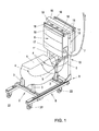
- FIG. 1 shows the perspective top view of a with a test specimen, such as for example an internal combustion engine, equipped pallet construction, prepared for Transport, for example, to a test bench, not shown here
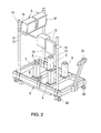
- FIG. 2 another Embodiment of such a pallet construction without specimen
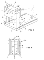
- Fig. 3 another Embodiment of a corresponding pallet construction with the specimen indicated
- FIG. 4 shows a partial section through a pallet construction, for example in accordance with Fig. 1 or Fig. 3 in the area of the support arrangement for receiving and fastening various Signal conditioning units - for example along the line IV - IV in Fig. 3 in enlarged scale.
- test object 1 For example an internal combustion engine schematically shown in FIGS. 1 and 3, 1 to 3, the test object 1 is mounted on a holding device 2, which is usually has spatially adjustable holding elements 3, which adapt the actual stopping points allow to different test objects 1.
- sensors 4 only indicated in Fig. 1
- signals 5 with signal conditioning units 6 and from there via a common signal connection 7 connected to an evaluation device, not shown, on the test bench become.
- the entire pallet construction 8, which is preferably a self-propelled Base part 9, the holding elements 3 of the holding device 2 arranged thereon and a support arrangement 10 for receiving and fastening the signal conditioning units 6 has in advance and away from the test bench in a setup area with the test object 1, the sensors 4, the signal conditioning units 6 and the signal lines 5 provided and then transported in the fully equipped state to the test bench, where only still the signal connection 7 (for example a simple bus line) between the signal conditioning units 6 on the pallet construction 8 and the one not shown here Evaluation device is installed.
- DUT 1 is also in the test room of the Test bench then, for example, with an electric drive or a power brake or the like.
- To connect - a shaft protection tunnel is shown in Fig. 1 and designated 11.
- Fig. 2 On the support arrangement 10 can, for example, indicated in Fig. 2 further measuring, display or operating elements 12 can also be attached, these also can be separated from the signal conditioning units 6.
- the equipped pallet construction 8, the others in the area of the base part 9 Function elements not shown here, such as heat exchangers, media connections or Like.
- the candidate can take this opportunity, or separately before the installation the loaded pallet construction 8 in a conditioning area, also pretreated, for example brought to operating temperature.
- the support arrangement 10 has at least in all of the exemplary embodiments shown here two lateral uprights 13, which according to FIG. 1 are telescopic, for example by means of a hand winch, or also electrically, pneumatically or hydraulically, extendable upper part 14, with which the signal conditioning units 6 on the test bench during implementation of tests can be further removed from the device under test 1, for example To minimize temperature or vibration loads. 1 as well 3, the two side uprights 13 (or 14) are connected to a cross member 15, decoupled via elastic elements 16, a receiving box 17 for the signal conditioning units 6 wears. That being said, the signal conditioning units could 6 - or even just some of them - in a rigidly designed support arrangement can also be stored separately from vibration.
- cooling or purge air openings 18, 19 are provided on the top of the receiving box 17 cooling or purge air openings 18, 19 to see.
- the cooling air supplied through the openings 18 is conditioned, specially filtered or cooled separately, and flows through the interior the double-walled support arrangement 10 or receiving box 17 along the Arrow 20 (Fig. 4), with which the signal conditioning units arranged in the interior 21 6 can be cooled if necessary.
- ambient air as Purge air through the outer part of the double-walled receiving box 17, with what Heat input from the outside, for example from device under test 1, is prevented.
- Openings corresponding to the openings 18 and 19 are each at one in FIG. 3 the two uprights 13 are provided in the region of their connection to the base part 9, in this case the two uprights 13 and the cross member 15 via their hollow interiors connected - the separate supply of cooling air and purge air to the receiving box 17 is not shown separately in FIG. 3.
- the carrying arrangement 10 or receiving box 17 can also be used in whole or in part an EMC shielding, which is particularly advantageous if the individual signal conditioning units 6 to be accommodated therein are not themselves such Have shielding.
- FIGS. 1 and 2 on the underside of the Base part 9 provided transport rollers 22 with which the pallet construction 8 itself is mobile. 2 is similar to a lift truck Operating device 23 is provided, with which the entire pallet construction 8 for moving can be raised and lowered in place.
- the pallet construction 8 according to 3, on the other hand, is not itself drivable and can, for example, by means of a forklift be transported. 1 to 3 can be in the test room of the test bench also driven on docking ramps, for example, and kept stable there, in all cases, at least some of the required medium connections are also directly connected can be docked.
Landscapes
- Physics & Mathematics (AREA)
- General Physics & Mathematics (AREA)
- Testing Of Engines (AREA)
- Testing Of Devices, Machine Parts, Or Other Structures Thereof (AREA)
Abstract
Description
Claims (10)
- Verfahren zur Vorbereitung und Durchführung von Prüfstandsversuchen an einem Prüfling (1), insbesonders an einem oder mehreren zusammenwirkenden Element(en) eines Fahrzeuges, wie beispielsweise einer Brennkraftmaschine oder Teilen eines Antriebsstranges, wobei der Prüfling (1) auf eine Halteeinrichtung (2) montiert und mit Sensoren (4) entsprechend den durchzuführenden Versuchen versehen wird, wobei die Sensoren (4) über Signalleitungen (5) mit einer Auswerteeinrichtung verbunden werden und wobei dann die Prüfstandsversuche vorgenommen werden, dadurch gekennzeichnet, dass die Montage des Prüflings (1) auf einer transportablen Palettenkonstruktion (8) abseits des Prüfstandes in einem Rüstbereich erfolgt, dass bereits vorher oder ebenfalls im Rüstbereich die Sensoren (4) angebracht und entsprechende Signalkonditionierungseinheiten (6) an der Palettenkonstruktion (8) angeordnet und mit den Sensoren (4) verbunden werden, und dass die derart bestückte Palettenkonstruktion (8) dann an den Prüfstand transportiert und dort durch Herstellen einer Signalverbindung (7) zwischen den Signalkonditionierungseinheiten (6) an der Palettenkonstruktion und der Auswerteeinrichtung installiert wird.
- Verfahren nach Anspruch 1, dadurch gekennzeichnet, dass die bestückte Palettenkonstruktion (8) vor der Installierung am Prüfstand noch im Rüstbereich oder einem im Transportweg vor dem Prüfstand gelegenen Testbereich funktional geprüft wird.
- Verfahren nach Anspruch 1 oder 2, dadurch gekennzeichnet, dass der Prüfling (1) vor der Installierung der bestückten Palettenkonstruktion (8) am Prüfstand in einem Konditionierbereich vorbehandelt, beispielsweise auf Betriebstemperatur gebracht, wird.
- Palettenkonstruktion zur Verwendung in einem Verfahren nach einem der Ansprüche 1 bis 3, mit einem vorzugsweise selbst fahrbaren Basisteil (9), darauf angeordneten, vorzugsweise zur Aufnahme verschiedener Prüflinge (1) räumlich verstellbaren Halteelementen (3) und einer Traganordnung (10), insbesonders zur Aufnahme und Befestigung verschiedener Signalkonditionierungseinheiten (6).
- Palettenkonstruktion nach Anspruch 4, dadurch gekennzeichnet, dass die Traganordnung (10) relativ zum Basisteil (9) verstellbar und/oder gegenüber diesem schwingungsisoliert aufgehängt ist.
- Palettenkonstruktion nach Anspruch 4 oder 5, dadurch gekennzeichnet, dass die Signalkonditionierungseinheiten (6) in der Traganordnung (10) schwingungsisoliert gelagert sind.
- Palettenkonstruktion nach einem der Ansprüche 4 bis 6, dadurch gekennzeichnet, dass die Signalkonditionierungseinheiten (6) mittels in der Traganordnung (10, 17) angeordneter Strömungskanäle für Kühlmedium kühlbar sind.
- Palettenkonstruktion nach Anspruch 7, dadurch gekennzeichnet, dass die Traganordnung (10 ,17) für die Signalkonditionierungseinheiten (6) zumindest zum Teil doppelwandig ausgeführt ist, wobei ein damit gebildeter, zumindest auf einer Seite an die Signalkonditionierungseinheiten (6) angrenzender Hohlraum mit einer Kühlmediumzu- und - ableitung, vorzugsweise für Umgebungsluft, verbunden ist.
- Palettenkonstruktion nach Anspruch 8, dadurch gekennzeichnet, dass der die Signalkonditionierungseinheiten (6) aufnehmende Innenraum (21) der doppelwandigen Traganordnung (10, 17) separat über Zu- und Ableitungen mit gefilterter Kühlluft gekühlt ist.
- Palettenkonstruktion nach einem oder mehreren der Ansprüche 4 bis 9, dadurch gekennzeichnet, dass die Traganordnung (10, 17) für die Signalkonditionierungseinheiten (6) eine EMV-Abschirmung aufweist.
Applications Claiming Priority (2)
| Application Number | Priority Date | Filing Date | Title |
|---|---|---|---|
| AT0038303U AT6393U3 (de) | 2003-06-02 | 2003-06-02 | Verfahren zur vorbereitung und durchführung von prüfstandsversuchen sowie palettenkonstruktion zur verwendung in einem derartigen verfahren |
| AT3832003U | 2003-06-02 |
Publications (2)
| Publication Number | Publication Date |
|---|---|
| EP1484591A1 true EP1484591A1 (de) | 2004-12-08 |
| EP1484591B1 EP1484591B1 (de) | 2011-09-21 |
Family
ID=27625579
Family Applications (1)
| Application Number | Title | Priority Date | Filing Date |
|---|---|---|---|
| EP04450099A Expired - Lifetime EP1484591B1 (de) | 2003-06-02 | 2004-04-28 | Verfahren zur Vorbereitung und Durchführung von Prüfstandsversuchen sowie Palettenkonstruktion zur Verwendung in einem derartigen Verfahren |
Country Status (2)
| Country | Link |
|---|---|
| EP (1) | EP1484591B1 (de) |
| AT (2) | AT6393U3 (de) |
Cited By (8)
| Publication number | Priority date | Publication date | Assignee | Title |
|---|---|---|---|---|
| EP2196876A1 (de) | 2008-12-15 | 2010-06-16 | AVL List GmbH | Verfahren und Steuergerätepalette zum Vorrüsten eines Steuergeräteverbundes |
| AT11170U3 (de) * | 2009-12-23 | 2010-11-15 | Avl List Gmbh | Palettenkonstruktion, prüfstand zur aufnahme der palettenkonstruktion und verfahren zur vorbereitung von prüfstandsversuchen mit einer solchen palettenkonstruktion |
| EP2477022A1 (de) * | 2011-01-13 | 2012-07-18 | AVL List GmbH | Palettensystem mit einer Rüstpalette und einer Rüstpalettenaufnahme |
| DE102012212886A1 (de) * | 2012-07-23 | 2014-01-23 | Bayerische Motoren Werke Aktiengesellschaft | Mobiler Prüfstandaufbau auf einer fahrbaren Palettenkonstruktion zur Durchführung einer EMV-Messung |
| AT518652B1 (de) * | 2016-12-30 | 2017-12-15 | Avl List Gmbh | Stützvorrichtung |
| US20180148187A1 (en) * | 2015-07-31 | 2018-05-31 | Safran Nacelles | Acoustic attenuation structure with a plurality of attenuation degrees for a propulsion assembly of an aircraft |
| CN110207989A (zh) * | 2019-05-29 | 2019-09-06 | 太原理工大学 | 一种发动机台架自动对中调节系统 |
| CN119269108A (zh) * | 2024-10-16 | 2025-01-07 | 北京航空航天大学 | 涡轮叶片双层壁气冷结构模拟件、测试夹具和测试系统 |
Families Citing this family (1)
| Publication number | Priority date | Publication date | Assignee | Title |
|---|---|---|---|---|
| AT501579B1 (de) * | 2004-12-01 | 2007-03-15 | Avl List Gmbh | Prüfstandsanordnung für fahrzeuge |
Citations (4)
| Publication number | Priority date | Publication date | Assignee | Title |
|---|---|---|---|---|
| US4932628A (en) | 1988-03-03 | 1990-06-12 | Pacheco Orlando D | Portable engine test stand |
| AT407922B (de) | 1995-04-21 | 2001-07-25 | Sondey Thomas F | Vorrichtung zum zuführen eines verbrennungsmotors zu einem motorprüfplatz, paletteneinheit und verfahren zur anbringung eines zu testenden verbrennungsmotors an einem motorprüfplatz |
| US20010039832A1 (en) | 1999-04-01 | 2001-11-15 | Sondey Thomas F. | Modular engine delivery apparatus |
| DE10049192A1 (de) | 2000-10-05 | 2002-04-11 | Daimler Chrysler Ag | Verfahren zum mobilen Prüfen von Aggregaten, insbesondere von Kraftfahrzeug-Motoren und -Getrieben |
Family Cites Families (1)
| Publication number | Priority date | Publication date | Assignee | Title |
|---|---|---|---|---|
| DE10049193B4 (de) * | 2000-10-05 | 2013-07-11 | Daimler Ag | Verfahren, dessen Verwendung und Vorrichtung zum mobilen Prüfen von Aggregaten, insbesondere von Kraftfahrzeug-Motoren und -Getrieben |
-
2003
- 2003-06-02 AT AT0038303U patent/AT6393U3/de not_active IP Right Cessation
-
2004
- 2004-04-28 EP EP04450099A patent/EP1484591B1/de not_active Expired - Lifetime
- 2004-04-28 AT AT04450099T patent/ATE525629T1/de active
Patent Citations (4)
| Publication number | Priority date | Publication date | Assignee | Title |
|---|---|---|---|---|
| US4932628A (en) | 1988-03-03 | 1990-06-12 | Pacheco Orlando D | Portable engine test stand |
| AT407922B (de) | 1995-04-21 | 2001-07-25 | Sondey Thomas F | Vorrichtung zum zuführen eines verbrennungsmotors zu einem motorprüfplatz, paletteneinheit und verfahren zur anbringung eines zu testenden verbrennungsmotors an einem motorprüfplatz |
| US20010039832A1 (en) | 1999-04-01 | 2001-11-15 | Sondey Thomas F. | Modular engine delivery apparatus |
| DE10049192A1 (de) | 2000-10-05 | 2002-04-11 | Daimler Chrysler Ag | Verfahren zum mobilen Prüfen von Aggregaten, insbesondere von Kraftfahrzeug-Motoren und -Getrieben |
Cited By (15)
| Publication number | Priority date | Publication date | Assignee | Title |
|---|---|---|---|---|
| EP2196876A1 (de) | 2008-12-15 | 2010-06-16 | AVL List GmbH | Verfahren und Steuergerätepalette zum Vorrüsten eines Steuergeräteverbundes |
| AT11170U3 (de) * | 2009-12-23 | 2010-11-15 | Avl List Gmbh | Palettenkonstruktion, prüfstand zur aufnahme der palettenkonstruktion und verfahren zur vorbereitung von prüfstandsversuchen mit einer solchen palettenkonstruktion |
| DE102010053799A1 (de) | 2009-12-23 | 2012-02-09 | Avl List Gmbh | Palettenkonstruktion, Prüfstand zur Aufnahme der Palettenkonstruktion und Verfahren zur Vorbereitung von Prüfstandsversuchen mit einer solchen Palettenkonstruktion |
| CN102607856B (zh) * | 2011-01-13 | 2014-09-03 | Avl里斯脱有限公司 | 包含安装托架和安装托架接纳装置的托架系统 |
| EP2477022A1 (de) * | 2011-01-13 | 2012-07-18 | AVL List GmbH | Palettensystem mit einer Rüstpalette und einer Rüstpalettenaufnahme |
| CN102607856A (zh) * | 2011-01-13 | 2012-07-25 | Avl里斯脱有限公司 | 包含安装托架和安装托架接纳装置的托架系统 |
| US8448930B2 (en) | 2011-01-13 | 2013-05-28 | Avl List Gmbh | Pallet system comprising a setup pallet and a setup pallet receptacle |
| DE102012212886A1 (de) * | 2012-07-23 | 2014-01-23 | Bayerische Motoren Werke Aktiengesellschaft | Mobiler Prüfstandaufbau auf einer fahrbaren Palettenkonstruktion zur Durchführung einer EMV-Messung |
| WO2014016173A3 (de) * | 2012-07-23 | 2014-03-13 | Bayerische Motoren Werke Aktiengesellschaft | Mobiler prüfstandaufbau auf einer fahrbaren palettenkonstruktion zur durchführung einer emv-messung |
| DE102012212886B4 (de) * | 2012-07-23 | 2017-08-03 | Bayerische Motoren Werke Aktiengesellschaft | Mobiler Prüfstandaufbau auf einer fahrbaren Palettenkonstruktion zur Durchführung einer EMV-Messung |
| US20180148187A1 (en) * | 2015-07-31 | 2018-05-31 | Safran Nacelles | Acoustic attenuation structure with a plurality of attenuation degrees for a propulsion assembly of an aircraft |
| AT518652B1 (de) * | 2016-12-30 | 2017-12-15 | Avl List Gmbh | Stützvorrichtung |
| AT518652A4 (de) * | 2016-12-30 | 2017-12-15 | Avl List Gmbh | Stützvorrichtung |
| CN110207989A (zh) * | 2019-05-29 | 2019-09-06 | 太原理工大学 | 一种发动机台架自动对中调节系统 |
| CN119269108A (zh) * | 2024-10-16 | 2025-01-07 | 北京航空航天大学 | 涡轮叶片双层壁气冷结构模拟件、测试夹具和测试系统 |
Also Published As
| Publication number | Publication date |
|---|---|
| EP1484591B1 (de) | 2011-09-21 |
| AT6393U2 (de) | 2003-09-25 |
| ATE525629T1 (de) | 2011-10-15 |
| AT6393U3 (de) | 2004-04-26 |
Similar Documents
| Publication | Publication Date | Title |
|---|---|---|
| DE102009051364B4 (de) | Schutzgehäuse für die Fahrzeugobjektprüfung | |
| EP1480867B1 (de) | Montagewerk für die montage von industriellen produkten | |
| DE3515010C2 (de) | Arbeitsverfahren und Prüfstand zur Untersuchung einer mit einer Brennkraftmaschine zusammenwirkenden Kfz-Einrichtung | |
| DE102009020182A1 (de) | Mobiler Prüfstand | |
| EP1484591B1 (de) | Verfahren zur Vorbereitung und Durchführung von Prüfstandsversuchen sowie Palettenkonstruktion zur Verwendung in einem derartigen Verfahren | |
| DE102005027986B4 (de) | Verfahren und Anlage zum Zusammenbauen von Bauteilen einer Fahrzeugkarosserie | |
| EP3151978B1 (de) | Anlage zum lackieren von gegenständen, insbesondere von fahrzeugkarosserien | |
| DE102009016807A1 (de) | Prüfstand zur Höhensimulation | |
| DE3118055C2 (de) | ||
| EP2477022B1 (de) | Palettensystem mit einer Rüstpalette und einer Rüstpalettenaufnahme | |
| DE202009015830U1 (de) | Modulares verfahrbares Meßportal | |
| DE69604186T2 (de) | Testvorrichtung zum Prüfen von Kraftfahrzeug-Brennkraftmaschinen | |
| DE102007036709A1 (de) | Anlauffertigungslinie für Rohbau-Karosserien | |
| DE102018128713A1 (de) | Vorrichtung zur Kühlung der Betriebsumgebung einer Prüfstandsmotoreneinheit | |
| DE29816231U1 (de) | Mobile Station | |
| AT501579B1 (de) | Prüfstandsanordnung für fahrzeuge | |
| DE10360143B4 (de) | Verfahren zum Prüfen der Dichtheit eines Aggregats und Prüfsystem zur Durchführung des Verfahrens | |
| EP1459043B1 (de) | Verfahren zur leistungsermittlung und leistungsprüfstand für einen verbrennungsmotor | |
| AT528206B1 (de) | Vorrichtung zur Messung eines Luftmassenstroms auf einem Prüfstand | |
| EP1764542A1 (de) | Bausatz zur Erstellung einer Industrieanlage | |
| DE102009008927A1 (de) | Vorrichtung zum wahlweisen Beschicken mehrerer Förderleitungen mit einem Schüttgut | |
| DE2733938A1 (de) | Ackerschlepper in halbrahmenbauweise | |
| DE102018221677B4 (de) | Aufnahmevorrichtung mit einer Wechselvorrichtung für Module eines Windkanalprüfstands und Windkanalprüfstand sowie Verfahren zum Wechseln eines Moduls in einem Windkanalprüfstand | |
| EP2934776B1 (de) | Kraftfahrzeugprüfstand | |
| DE19634503B4 (de) | Straßenfertiger |
Legal Events
| Date | Code | Title | Description |
|---|---|---|---|
| PUAI | Public reference made under article 153(3) epc to a published international application that has entered the european phase |
Free format text: ORIGINAL CODE: 0009012 |
|
| AK | Designated contracting states |
Kind code of ref document: A1 Designated state(s): AT BE BG CH CY CZ DE DK EE ES FI FR GB GR HU IE IT LI LU MC NL PL PT RO SE SI SK TR |
|
| AX | Request for extension of the european patent |
Extension state: AL HR LT LV MK |
|
| 17P | Request for examination filed |
Effective date: 20050518 |
|
| AKX | Designation fees paid |
Designated state(s): AT BE BG CH CY CZ DE DK EE ES FI FR GB GR HU IE IT LI LU MC NL PL PT RO SE SI SK TR |
|
| 17Q | First examination report despatched |
Effective date: 20070326 |
|
| GRAP | Despatch of communication of intention to grant a patent |
Free format text: ORIGINAL CODE: EPIDOSNIGR1 |
|
| GRAS | Grant fee paid |
Free format text: ORIGINAL CODE: EPIDOSNIGR3 |
|
| GRAA | (expected) grant |
Free format text: ORIGINAL CODE: 0009210 |
|
| AK | Designated contracting states |
Kind code of ref document: B1 Designated state(s): AT BE BG CH CY CZ DE DK EE ES FI FR GB GR HU IE IT LI LU MC NL PL PT RO SE SI SK TR |
|
| REG | Reference to a national code |
Ref country code: GB Ref legal event code: FG4D Free format text: NOT ENGLISH |
|
| REG | Reference to a national code |
Ref country code: CH Ref legal event code: EP |
|
| REG | Reference to a national code |
Ref country code: IE Ref legal event code: FG4D Free format text: LANGUAGE OF EP DOCUMENT: GERMAN |
|
| REG | Reference to a national code |
Ref country code: DE Ref legal event code: R096 Ref document number: 502004012879 Country of ref document: DE Effective date: 20111117 |
|
| REG | Reference to a national code |
Ref country code: NL Ref legal event code: VDEP Effective date: 20110921 |
|
| PG25 | Lapsed in a contracting state [announced via postgrant information from national office to epo] |
Ref country code: SE Free format text: LAPSE BECAUSE OF FAILURE TO SUBMIT A TRANSLATION OF THE DESCRIPTION OR TO PAY THE FEE WITHIN THE PRESCRIBED TIME-LIMIT Effective date: 20110921 Ref country code: FI Free format text: LAPSE BECAUSE OF FAILURE TO SUBMIT A TRANSLATION OF THE DESCRIPTION OR TO PAY THE FEE WITHIN THE PRESCRIBED TIME-LIMIT Effective date: 20110921 |
|
| PG25 | Lapsed in a contracting state [announced via postgrant information from national office to epo] |
Ref country code: CY Free format text: LAPSE BECAUSE OF FAILURE TO SUBMIT A TRANSLATION OF THE DESCRIPTION OR TO PAY THE FEE WITHIN THE PRESCRIBED TIME-LIMIT Effective date: 20110921 Ref country code: GR Free format text: LAPSE BECAUSE OF FAILURE TO SUBMIT A TRANSLATION OF THE DESCRIPTION OR TO PAY THE FEE WITHIN THE PRESCRIBED TIME-LIMIT Effective date: 20111222 Ref country code: SI Free format text: LAPSE BECAUSE OF FAILURE TO SUBMIT A TRANSLATION OF THE DESCRIPTION OR TO PAY THE FEE WITHIN THE PRESCRIBED TIME-LIMIT Effective date: 20110921 |
|
| REG | Reference to a national code |
Ref country code: IE Ref legal event code: FD4D |
|
| PG25 | Lapsed in a contracting state [announced via postgrant information from national office to epo] |
Ref country code: CZ Free format text: LAPSE BECAUSE OF FAILURE TO SUBMIT A TRANSLATION OF THE DESCRIPTION OR TO PAY THE FEE WITHIN THE PRESCRIBED TIME-LIMIT Effective date: 20110921 Ref country code: IE Free format text: LAPSE BECAUSE OF FAILURE TO SUBMIT A TRANSLATION OF THE DESCRIPTION OR TO PAY THE FEE WITHIN THE PRESCRIBED TIME-LIMIT Effective date: 20110921 Ref country code: SK Free format text: LAPSE BECAUSE OF FAILURE TO SUBMIT A TRANSLATION OF THE DESCRIPTION OR TO PAY THE FEE WITHIN THE PRESCRIBED TIME-LIMIT Effective date: 20110921 |
|
| PG25 | Lapsed in a contracting state [announced via postgrant information from national office to epo] |
Ref country code: NL Free format text: LAPSE BECAUSE OF FAILURE TO SUBMIT A TRANSLATION OF THE DESCRIPTION OR TO PAY THE FEE WITHIN THE PRESCRIBED TIME-LIMIT Effective date: 20110921 Ref country code: PL Free format text: LAPSE BECAUSE OF FAILURE TO SUBMIT A TRANSLATION OF THE DESCRIPTION OR TO PAY THE FEE WITHIN THE PRESCRIBED TIME-LIMIT Effective date: 20110921 Ref country code: PT Free format text: LAPSE BECAUSE OF FAILURE TO SUBMIT A TRANSLATION OF THE DESCRIPTION OR TO PAY THE FEE WITHIN THE PRESCRIBED TIME-LIMIT Effective date: 20120123 Ref country code: RO Free format text: LAPSE BECAUSE OF FAILURE TO SUBMIT A TRANSLATION OF THE DESCRIPTION OR TO PAY THE FEE WITHIN THE PRESCRIBED TIME-LIMIT Effective date: 20110921 Ref country code: EE Free format text: LAPSE BECAUSE OF FAILURE TO SUBMIT A TRANSLATION OF THE DESCRIPTION OR TO PAY THE FEE WITHIN THE PRESCRIBED TIME-LIMIT Effective date: 20110921 |
|
| PLBI | Opposition filed |
Free format text: ORIGINAL CODE: 0009260 |
|
| PLAX | Notice of opposition and request to file observation + time limit sent |
Free format text: ORIGINAL CODE: EPIDOSNOBS2 |
|
| PG25 | Lapsed in a contracting state [announced via postgrant information from national office to epo] |
Ref country code: DK Free format text: LAPSE BECAUSE OF FAILURE TO SUBMIT A TRANSLATION OF THE DESCRIPTION OR TO PAY THE FEE WITHIN THE PRESCRIBED TIME-LIMIT Effective date: 20110921 |
|
| 26 | Opposition filed |
Opponent name: TECHNOGERMA SYSTEMS GMBH Effective date: 20120621 |
|
| REG | Reference to a national code |
Ref country code: DE Ref legal event code: R026 Ref document number: 502004012879 Country of ref document: DE Effective date: 20120621 |
|
| BERE | Be: lapsed |
Owner name: AVL LIST GMBH Effective date: 20120430 |
|
| PG25 | Lapsed in a contracting state [announced via postgrant information from national office to epo] |
Ref country code: MC Free format text: LAPSE BECAUSE OF NON-PAYMENT OF DUE FEES Effective date: 20120430 |
|
| REG | Reference to a national code |
Ref country code: CH Ref legal event code: PL |
|
| PLBB | Reply of patent proprietor to notice(s) of opposition received |
Free format text: ORIGINAL CODE: EPIDOSNOBS3 |
|
| PG25 | Lapsed in a contracting state [announced via postgrant information from national office to epo] |
Ref country code: BE Free format text: LAPSE BECAUSE OF NON-PAYMENT OF DUE FEES Effective date: 20120430 Ref country code: LI Free format text: LAPSE BECAUSE OF NON-PAYMENT OF DUE FEES Effective date: 20120430 Ref country code: CH Free format text: LAPSE BECAUSE OF NON-PAYMENT OF DUE FEES Effective date: 20120430 |
|
| REG | Reference to a national code |
Ref country code: CH Ref legal event code: PK Free format text: DAS PRIORITAETSAKTENZEICHEN WURDE BERICHTIGT: AT 38303 U / 02.06.2003 |
|
| PG25 | Lapsed in a contracting state [announced via postgrant information from national office to epo] |
Ref country code: ES Free format text: LAPSE BECAUSE OF FAILURE TO SUBMIT A TRANSLATION OF THE DESCRIPTION OR TO PAY THE FEE WITHIN THE PRESCRIBED TIME-LIMIT Effective date: 20120101 |
|
| PG25 | Lapsed in a contracting state [announced via postgrant information from national office to epo] |
Ref country code: BG Free format text: LAPSE BECAUSE OF FAILURE TO SUBMIT A TRANSLATION OF THE DESCRIPTION OR TO PAY THE FEE WITHIN THE PRESCRIBED TIME-LIMIT Effective date: 20111221 |
|
| PLAB | Opposition data, opponent's data or that of the opponent's representative modified |
Free format text: ORIGINAL CODE: 0009299OPPO |
|
| R26 | Opposition filed (corrected) |
Opponent name: TECHNOGERMA SYSTEMS GMBH Effective date: 20120621 |
|
| PG25 | Lapsed in a contracting state [announced via postgrant information from national office to epo] |
Ref country code: TR Free format text: LAPSE BECAUSE OF FAILURE TO SUBMIT A TRANSLATION OF THE DESCRIPTION OR TO PAY THE FEE WITHIN THE PRESCRIBED TIME-LIMIT Effective date: 20110921 |
|
| PG25 | Lapsed in a contracting state [announced via postgrant information from national office to epo] |
Ref country code: LU Free format text: LAPSE BECAUSE OF NON-PAYMENT OF DUE FEES Effective date: 20120428 |
|
| PG25 | Lapsed in a contracting state [announced via postgrant information from national office to epo] |
Ref country code: HU Free format text: LAPSE BECAUSE OF FAILURE TO SUBMIT A TRANSLATION OF THE DESCRIPTION OR TO PAY THE FEE WITHIN THE PRESCRIBED TIME-LIMIT Effective date: 20040428 |
|
| PLBP | Opposition withdrawn |
Free format text: ORIGINAL CODE: 0009264 |
|
| PLBD | Termination of opposition procedure: decision despatched |
Free format text: ORIGINAL CODE: EPIDOSNOPC1 |
|
| PLBM | Termination of opposition procedure: date of legal effect published |
Free format text: ORIGINAL CODE: 0009276 |
|
| STAA | Information on the status of an ep patent application or granted ep patent |
Free format text: STATUS: OPPOSITION PROCEDURE CLOSED |
|
| 27C | Opposition proceedings terminated |
Effective date: 20150420 |
|
| REG | Reference to a national code |
Ref country code: FR Ref legal event code: PLFP Year of fee payment: 13 |
|
| REG | Reference to a national code |
Ref country code: FR Ref legal event code: PLFP Year of fee payment: 14 |
|
| REG | Reference to a national code |
Ref country code: FR Ref legal event code: PLFP Year of fee payment: 15 |
|
| PGFP | Annual fee paid to national office [announced via postgrant information from national office to epo] |
Ref country code: DE Payment date: 20180420 Year of fee payment: 15 |
|
| PGFP | Annual fee paid to national office [announced via postgrant information from national office to epo] |
Ref country code: AT Payment date: 20180424 Year of fee payment: 15 Ref country code: IT Payment date: 20180423 Year of fee payment: 15 Ref country code: FR Payment date: 20180420 Year of fee payment: 15 |
|
| PGFP | Annual fee paid to national office [announced via postgrant information from national office to epo] |
Ref country code: GB Payment date: 20180418 Year of fee payment: 15 |
|
| REG | Reference to a national code |
Ref country code: DE Ref legal event code: R119 Ref document number: 502004012879 Country of ref document: DE |
|
| REG | Reference to a national code |
Ref country code: AT Ref legal event code: MM01 Ref document number: 525629 Country of ref document: AT Kind code of ref document: T Effective date: 20190428 |
|
| GBPC | Gb: european patent ceased through non-payment of renewal fee |
Effective date: 20190428 |
|
| PG25 | Lapsed in a contracting state [announced via postgrant information from national office to epo] |
Ref country code: DE Free format text: LAPSE BECAUSE OF NON-PAYMENT OF DUE FEES Effective date: 20191101 Ref country code: GB Free format text: LAPSE BECAUSE OF NON-PAYMENT OF DUE FEES Effective date: 20190428 Ref country code: AT Free format text: LAPSE BECAUSE OF NON-PAYMENT OF DUE FEES Effective date: 20190428 |
|
| PG25 | Lapsed in a contracting state [announced via postgrant information from national office to epo] |
Ref country code: IT Free format text: LAPSE BECAUSE OF NON-PAYMENT OF DUE FEES Effective date: 20190428 |
|
| PG25 | Lapsed in a contracting state [announced via postgrant information from national office to epo] |
Ref country code: FR Free format text: LAPSE BECAUSE OF NON-PAYMENT OF DUE FEES Effective date: 20190430 |