EP1484195B1 - Verkleidungsplatte mit einem Farbstreifen - Google Patents
Verkleidungsplatte mit einem Farbstreifen Download PDFInfo
- Publication number
- EP1484195B1 EP1484195B1 EP04450117A EP04450117A EP1484195B1 EP 1484195 B1 EP1484195 B1 EP 1484195B1 EP 04450117 A EP04450117 A EP 04450117A EP 04450117 A EP04450117 A EP 04450117A EP 1484195 B1 EP1484195 B1 EP 1484195B1
- Authority
- EP
- European Patent Office
- Prior art keywords
- stripe
- facing panel
- darker
- visible surface
- panel
- Prior art date
- Legal status (The legal status is an assumption and is not a legal conclusion. Google has not performed a legal analysis and makes no representation as to the accuracy of the status listed.)
- Expired - Lifetime
Links
Images
Classifications
-
- B—PERFORMING OPERATIONS; TRANSPORTING
- B44—DECORATIVE ARTS
- B44C—PRODUCING DECORATIVE EFFECTS; MOSAICS; TARSIA WORK; PAPERHANGING
- B44C5/00—Processes for producing special ornamental bodies
- B44C5/04—Ornamental plaques, e.g. decorative panels, decorative veneers
-
- E—FIXED CONSTRUCTIONS
- E04—BUILDING
- E04F—FINISHING WORK ON BUILDINGS, e.g. STAIRS, FLOORS
- E04F15/00—Flooring
- E04F15/02—Flooring or floor layers composed of a number of similar elements
- E04F15/04—Flooring or floor layers composed of a number of similar elements only of wood or with a top layer of wood, e.g. with wooden or metal connecting members
- E04F15/048—Flooring or floor layers composed of a number of similar elements only of wood or with a top layer of wood, e.g. with wooden or metal connecting members with a top surface of assembled elongated wooden strip type
Definitions
- the invention relates to a cladding panel according to the preamble of claim 1.
- Cladding panels for floors, walls or ceilings wherein on the longitudinal side surfaces of the cladding panel connection or locking elements (eg grooves and springs) are formed, which are formed along the two parallel longitudinal side edges of the cladding plate different or complementary to each other, so formed with different locking elements Longitudinal side edges of two cladding panels can be connected or joined together, are known, cf. e.g. DE-A-42 15 273.
- connection or locking elements e.g grooves and springs
- the aim of the invention is to simplify the laying of the cladding panels or the joining of individual cladding panels to a cladding surface.
- the measures to be taken should be as simple and inexpensive to form on the cladding panels.
- such a cladding panel should be given a visually appealing and consumers impressive appearance.
- a cladding panel of the type mentioned is characterized by the features cited in the characterizing part of claim 1.
- the technical effect of claim 1 according to the invention is that by providing a strip on the visible surface of the cladding panel the unskilled user is given guidance and assistance for laying. This makes it possible for a layman to arrange the cladding panels in the plane correctly to each other and to lay correctly.
- the strip indicates the position of the connecting or locking element and the user recognizes at a glance with which side surfaces the individual cladding panels are connectable or how they must be arranged. This can be worked faster and more effective.
- the cladding panels usually have to be cut on site to adapt to the spatial conditions.
- the trim panel In order to be able to cut the panels, the trim panel usually needs to be moved away from the immediate installation location to the cut-off location. There is a risk that the cladding panel is unconsciously rotated and then cut to the wrong side. This can lead to difficulties during subsequent installation, for example, if a provided on a broadside locking element is no longer available.
- the formation of the strip avoids this error because the user can orient themselves at the position of the strip.
- the intended darker strip in the case of assembled cladding panels gives the impression that a depression would be formed between the assembled cladding panels or along the joint, or that the flat surface would be provided with a groove.
- This addition to the technical effect additionally occurring aesthetic or visual impression is created by the longitudinal, darker stripes formed at a distance from the abutting edge of the visible surfaces of two assembled cladding panels.
- the connecting or locking elements which are selected to be able to connect together trim panels according to the invention, are formed along the circumference of the trim panel, in particular along the longitudinal side surfaces.
- These connecting elements can have any shape; Such connecting or locking elements are well known to the skilled person.
- These fasteners should hold together the cladding panels along their longitudinal side edges and possibly also along their transverse side surfaces in order to achieve a firmly connected structure of the cladding panels.
- a particularly advantageous appearance get the cladding panels or the visual impression of a groove formation is reinforced when the features of claim 2 are provided.
- the features of claims 3, 4 and 6 contribute to the enhancement of this visual impression.
- the base material of the cladding board is wood, wood-based material, medium density fiberboard or medium-density fiberboard (MDF), high density fibreboard or high-density fibreboard (HDF), wood chips or fiberboard material associated with adhesives.
- MDF medium density fiberboard or medium-density fiberboard
- HDF high density fibreboard or high-density fibreboard
- the surface and / or bottom surface of the cladding panel with a real wood or laminate coating or plastic pad are provided.
- the formation of the darker and / or the lighter stripe can take place differently.
- the darker and lighter stripes could be done by appropriate staining or coloring the wood surface.
- laminate coatings In applying laminate coatings to the surface of the trim panel, these laminate coatings could be prepared with strips and then bonded to the body of the trim panel.
- the areas of the lighter and / or darker strip are level with the rest of the visible surface, so as not to interrupt the level course of the surface of the cladding panels when walking.
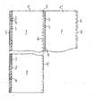
- a cladding panel 1 is shown schematically in plan view, which is joined together with a further cladding panel 1 'along the longitudinal side edges 4, 4'.
- the cladding panels 1, 1 ' springs 5 and grooves 6 are formed, which are adapted to each other and together as locking elements cladding panels 1, 1' together.
- the cladding panels 1, 1 ' have along their longitudinal side edge 4 a spring 5 and on the other longitudinal side edge 4' a groove 5 receiving groove 6.
- the coloring is kept darker than the color of the remaining visible surface 7 of the cladding panel 1, 1 '.
- This darker strip 2 gives the cladding panel 1, 1 'a special visual appearance or can be used as an aid for laying, since joinable cladding panels 1, 1' on the dark strip 2 near side always have the same locking element 5, which with the Locking element 6 cooperates, which runs parallel to the opposite longitudinal edge 4 ', which is the darker strip 2 away.
- the area between the darker strip 2 and the longitudinal side edge 4 can be made brighter than the color of the remaining visible surface 7 of the cladding panel 1. This enhances the visual impression achieved by the darker strip 2.
- the darker strip 2 and / or the lighter strip 3 may be formed by various techniques. In addition, especially coloring or pigmentation or insertion, in particular during the production process of a laminate surface, in question.
- the color of the visible surface 7 does not matter or can be chosen arbitrarily, in particular wood colors are chosen.
- the darker strip 2 and / or lighter strips 3 may preferably be kept in the same color as the visible surface 7 or deviate therefrom.
- Structures and / or grains formed in the visible surface preferably continue in the strip 2 and / or strip 3, but could also be interrupted by the strip 2 and / or strip 3, which could have a different surface structure.
- the boundary edges of the strip 2 are straight.
- the brightness of the strip 2 is 30 to 70%, preferably 40 to 60%, of the brightness of the visible surface 7.
Landscapes
- Engineering & Computer Science (AREA)
- Architecture (AREA)
- Life Sciences & Earth Sciences (AREA)
- Wood Science & Technology (AREA)
- Civil Engineering (AREA)
- Structural Engineering (AREA)
- Finishing Walls (AREA)
Description
- Die Erfindung betrifft eine Verkleidungsplatte gemäß dem Oberbegriff des Anspruchs 1.
- In der GB 1593281 sind dünne, tapetenartige Dekormaterialien mit Linienmustern in Form von Eckelementen und geraden Bahnen, die von einer Rolle abgelängt werden können, beschrieben. Zur Dekoration einer Decke eines Raumes werden zuerst in den Ecken des Raumes vier Eckelemente aufgeklebt und dann gegebenenfalls vier entsprechend von der Rolle abgelängte gerade Bahnen des Tapetenmaterials aufgeklebt. Die Anordnung der geraden Bahnen erfolgt entlang der Kante zwischen Decke und Wand, sodass die Linien ein kontinuierliches Muster ergeben.
- Verkleidungsplatten für Böden, Wände oder Decken, wobei auf den längsverlaufenden Seitenflächen der Verkleidungsplatte Verbindungs- bzw. Verriegelungselemente (z.B. Nuten und Federn) ausgebildet sind, die längs der beiden parallelen Längsseitenkanten der Verkleidungsplatte unterschiedlich bzw. zueinander komplementär ausgebildet sind, sodaß mit unterschiedlichen Verriegelungselementen ausgebildete Längsseitenkanten von zwei Verkleidungsplatten miteinander verbindbar bzw. zusammenfügbar sind, sind bekannt, vgl. z.B. DE-A-42 15 273.
- Ziel der Erfindung ist es, die Verlegung der Verkleidungsplatten bzw. das Zusammenfügen von einzelnen Verkleidungsplatten zu einer Verkleidungsfläche zu vereinfachen. Die dazu zu setzenden Maßnahmen sollen möglichst einfach und wenig aufwendig auf den Verkleidungsplatten auszubilden sein. Außerdem soll einer derartigen Verkleidungsplatte ein optisch ansprechendes und die Konsumenten beeindruckendes Aussehen verliehen werden.
- Erfindungsgemäß ist eine Verkleidungsplatte der eingangs genannten Art durch die im Kennzeichen des Anspruches 1 angeführten Merkmale charakterisiert.
- Die technische Wirkung des erfindungsgemäßen Anspruchs 1 ist die, dass durch die Anbringung eines Streifens auf der Sichtfläche der Verkleidungsplatte dem unkundigen Benutzer eine Anleitung und Hilfestellung zum Verlegen gegeben wird. Dadurch wird es einem Laien ermöglicht, die Verkleidungsplatten in der Ebene richtig zueinander anzuordnen und korrekt zu verlegen.
- Durch Ausbildung eines dunkleren Streifens können insbesondere bei Verkleidungsplatten, die an ihren Seitenflächen mit zusammenwirkenden Verbindungselementen versehen sind, die Verlegearbeiten vereinfacht werden, da bei der Verlegung lediglich eine Seitenkante ohne einen derartigen Streifen an eine Seitenkante mit einem derartigen Streifen angefügt werden muss, sodass ein aufwendiges Untersuchen der Verkleidungsplatten, welche Kante einer Verkleidungsplatte mit welcher Kante einer anderen Verkleidungsplatte zu verbinden ist, entfällt.
- Somit kennzeichnet der Streifen die Position des Verbindungs- bzw. Verriegelungselementes und der Benutzer erkennt auf den ersten Blick, mit welchen Seitenflächen die einzelnen Verkleidungsplatten verbindbar sind bzw. wie diese angeordnet werden müssen. Damit kann schneller und effektiver gearbeitet werden.
- Die Verkleidungsplatten müssen üblicherweise vor Ort zugeschnitten werden, um sich den räumlichen Gegebenheiten anzupassen. Um die Platten zuschneiden zu können, muss die Verkleidungsplatte üblicherweise vom unmittelbaren Verlegungsort weg zum Abschneideort gebracht werden. Dabei besteht die Gefahr, dass die Verkleidungsplatte unbewusst gedreht wird und anschließend an der falschen Seite abgelängt wird. Dies kann beim anschließenden Verlegen zu Schwierigkeiten führen, wenn beispielsweise ein an einer Breitseite vorgesehenes Verriegelungselement nicht mehr zur Verfügung steht. Durch die Ausbildung des Streifens wird diesem Fehler vorgebeugt, da sich der Benutzer an der Position des Streifens orientieren kann.
- Des Weiteren verleiht der vorgesehene dunklere Streifen bei zusammengefügten Verkleidungsplatten den Eindruck, als ob zwischen den zusammengefügten Verkleidungsplatten bzw. längs des Stoßes eine Vertiefung ausgebildet wäre bzw. die an sich ebene Fläche mit einer Nut versehen wäre. Dieser neben der technischen Wirkung zusätzlich auftretende ästhetische bzw. optische Eindruck entsteht durch den längsverlaufenden, dunkler ausgebildeten Streifen, der in Abstand von der Stoßkante der Sichtflächen von zwei zusammengefügten Verkleidungsplatten ausgebildet ist.
- Die Verbindungs- bzw. Verriegelungselemente, die gewählt werden, um erfindungsgemäße Verkleidungsplatten miteinander verbinden zu können, sind längs des Umfangs der Verkleidungsplatte, insbesondere längs der Längsseitenflächen, ausgebildet. Diese Verbindungselemente können beliebige Form aufweisen; derartige Verbindungs- bzw. Verriegelungselemente sind dem Fachmann wohl bekannt. Diese Verbindungselemente sollen die Verkleidungsplatten längs ihrer Längsseitenkanten und gegebenenfalls auch längs ihrer Querseitenflächen zusammenhalten, um ein fest verbundenes Gefüge der Verkleidungsplatten zu erreichen.
- Ein besonders vorteilhaftes Aussehen erhalten die Verkleidungsplatten bzw. der optische Eindruck einer Nutausbildung wird verstärkt, wenn die Merkmale des Anspruches 2 vorgesehen sind. Auch die Merkmale der Ansprüche 3, 4 und 6 tragen zur Verstärkung dieses optischen Eindrucks bei.
- Zweckmäßig ist es, wenn der Grundwerkstoff der Verkleidungsplatte Holz, Holzwerkstoff, Medium Density Fibreboard bzw. mittelverdichtete Faserplatten (MDF), High Density Fibreboard bzw. hochverdichtete Faserplatten (HDF), mit Klebstoffen verbundene Holzspäne bzw. Faserplattenwerkstoff ist.
- Von Vorteil ist es, wenn die Oberfläche und/oder Unterfläche der Verkleidungsplatte mit einer Echtholz- oder Laminatbeschichtung oder Kunststoffauflage versehen sind. Entsprechend der vorgesehenen Oberfläche kann die Ausbildung des dunkleren und/oder des helleren Streifens unterschiedlich erfolgen. Bei Echtholzböden bzw. Echtholzbeschichtungen könnte der dunklere und hellere Streifen durch entsprechendes Einbeizen bzw. Einfärben der Holzoberfläche erfolgen. Bei der Aufbringung von Laminatbeschichtungen auf die Oberfläche der Verkleidungsplatte könnten diese Laminatbeschichtungen mit Streifen vorbereitet und daraufhin mit dem Grundkörper der Verkleidungsplatte verbunden werden.
- Längs der Querseitenkanten, das heißt längs der Schmalseiten der rechteckigen Verkleidungsplatten, sind keine dunkleren oder helleren Streifen ausgebildet.
- Es versteht sich, dass die Bereiche des helleren und/oder dunkleren Streifens planeben mit der restlichen Sichtfläche ausgebildet sind, um beim Begehen den ebenen Verlauf der Oberfläche der Verkleidungsplatten nicht zu unterbrechen.
- Vorteilhafte Ausführungsformen der Erfindung ergeben sich aus der folgenden Beschreibung, den Patentansprüchen und der Zeichnung.
- In der Zeichnung ist schematisch eine Verkleidungsplatte 1 in Draufsicht dargestellt, die mit einer weiteren Verkleidungsplatte 1' entlang der Längsseitenkanten 4, 4' zusammengefügt ist. Dazu sind an den Längsseitenflächen der Verkleidungsplatten 1, 1' Federn 5 und Nuten 6 ausgebildet, die aneinander angepasst sind und als Verriegelungselemente zusammengefügte Verkleidungsplatten 1, 1' zusammenhalten. Die Verkleidungsplatten 1, 1' weisen entlang ihrer längsverlaufenden Seitenkante 4 eine Feder 5 und auf der anderen längsverlaufenden Seitenkante 4' eine eine Feder 5 aufnehmende Nut 6 auf. Entlang einer der beiden Seitenkanten 4 oder 4' jeder Verkleidungsplatte 1, 1' verläuft in Längsrichtung ein Streifen 2, dessen Farbgebung dunkler gehalten ist als die Farbgebung der restlichen Sichtfläche 7 der Verkleidungsplatte 1, 1'.
- Dieser dunklere Streifen 2 verleiht der Verkleidungsplatte 1, 1' ein besonderes optisches Aussehen bzw. kann als Hilfsmittel für die Verlegung herangezogen werden, da zusammenfügbare Verkleidungsplatten 1, 1' an der dem dunklen Streifen 2 nahen Seite immer dasselbe Verriegelungselement 5 besitzen, das mit dem Verriegelungselement 6 zusammenwirkt, das parallel zur gegenüberliegenden Längskante 4' verläuft, die dem dunkleren Streifen 2 entfernt liegt.
- Der Bereich zwischen dem dunkleren Streifen 2 und der Längsseitenkante 4 kann heller ausgebildet sein als die Farbtönung der restlichen Sichtfläche 7 der Verkleidungsplatte 1. Damit wird der optische Eindruck, der durch den dunkleren Streifen 2 erreicht wird, noch verstärkt.
- Der dunklere Streifen 2 und/oder der hellere Streifen 3 können durch verschiedenartige Techniken ausgebildet werden. Dazu kommen vor allem Einfärben bzw. Pigmentieren oder Einsetzen, insbesondere beim Herstellungsvorgang einer Laminatoberfläche, in Frage.
- Die Farbe der Sichtfläche 7 spielt keine Rolle bzw. kann beliebig gewählt werden, insbesondere werden Holzfarben gewählt. Der dunklere Streifen 2 und/oder hellere Streifen 3 können bevorzugt in demselben Farbton wie die Sichtfläche 7 gehalten sein oder davon abweichen.
- In der Sichtfläche ausgebildete Strukturen und/oder Maserungen verlaufen bevorzugt in den Streifen 2 und/oder Streifen 3 weiter, könnten aber auch durch den Streifen 2 und/oder Streifen 3 unterbrochen werden, der (die) eine andere Oberflächenstruktur besitzen könnte(n).
- Die Begrenzungsränder des Streifens 2 verlaufen gerade.
- Auf der Sichtfläche 7 einer Verkleidungsplatte 1 ist lediglich ein einziger Streifen 2 ausgebildet. Die Helligkeit des Streifens 2 beträgt 30 bis 70 %, vorzugsweise 40 bis 60 %, der Helligkeit der Sichtfläche 7.
Claims (10)
- Verkleidungsplatte, insbesondere für Böden, Wände oder Decken, wobei auf den längsverlaufenden Seitenflächen der Verkleidungsplatte (1, 1') Verbindungs- bzw. Verriegelungselemente (5, 6), z.B. Nuten und Federn, ausgebildet sind, die längs der beiden parallelen Längsseitenkanten (4, 4') der Verkleidungsplatte (1, 1') unterschiedlich bzw. zueinander komplementär ausgebildet sind, sodass mit unterschiedlichen Verriegelungselementen ausgebildete Längsseitenkanten (4, 4') von zwei Verkleidungsplatten (1) miteinander verbindbar bzw. verriegelbar bzw. zusammenfügbar sind, dadurch gekennzeichnet, dass auf der Sichtfläche (7) der Verkleidungsplatte (1, 1') parallel und in geringem Abstand zu einer der beiden längsverlaufenden Seitenkanten (4, 4') der Sichtfläche (7) ein einziger Streifen (2) ausgebildet ist, z.B. aufgetragen, eingefärbt, pigmentiert, eingesetzt ist, dessen Farbgebung dunkler ist als die Farbgebung der restlichen Sichtfläche, wobei längs der Längsseitenkante (4) der Verkleidungsplatte (1, 1') zu der der Streifen (2) parallel verläuft bzw. dieser nahe liegt, immer ein und dasselbe Verbindungs- bzw. Verriegelungselement (5) ausgebildet ist und an der gegenüberliegenden Längsseitenkante (4') immer ein und dasselbe Verbindungs- bzw. Verriegelungselement (6) ausgebildet ist, das komplementär zum bzw. mit dem Verbindungs- bzw. Verriegelungselement (5) zusammenfügbar ausgebildet ist.
- Verkleidungsplatte nach Anspruch 1, dadurch gekennzeichnet, dass der Bereich zwischen dem dunkler als die Sichtfläche ausgebildeten Streifen (2) und der nahen Seitenkante (4) der Sichtfläche (7) heller ist als die Farbgebung der restlichen Sichtfläche (7), bzw. dass zwischen dem dunkleren Streifen (2) und der Seitenkante (4) ein gegenüber der Sichtfläche (7) hellerer Streifen (3) ausgebildet ist, z.B. aufgetragen, eingefärbt, pigmentiert, eingesetzt.
- Verkleidungsplatte nach Anspruch 1 oder 2, dadurch gekennzeichnet, dass die Breite des helleren Streifens (3) 80 bis 120 %, vorzugsweise 90 bis 110 %, der Breite des dunkleren Streifens (2) beträgt.
- Verkleidungsplatte nach einem der Ansprüche 1 bis 3, dadurch gekennzeichnet, dass der Abstand des dunkleren Streifens (2) von der nahen Seitenkante (4) 80 bis 120 %, vorzugsweise 90 bis 110 %, der Breite des dunkleren Streifens (2) beträgt.
- Verkleidungsplatte nach einem der Ansprüche 1 bis 4, dadurch gekennzeichnet, dass sich der dunklere Streifen (2) und gegebenenfalls auch der hellere Streifen (3) über die gesamte Länge der Verkleidungsplatte (1) bzw. der Sichtfläche (7) erstrecken.
- Verkleidungsplatte nach einem der Ansprüche 1 bis 5, dadurch gekennzeichnet, dass die Breite des dunkleren Streifens (2) und/oder des helleren Streifens (3) 0,5 bis 4 %, vorzugsweise 1 bis 3 %, der Breite der Verkleidungsplatte (1) bzw. der Sichtfläche (7) beträgt.
- Verkleidungsplatte nach einem der Ansprüche 1 bis 6, dadurch gekennzeichnet, dass der Bereich des dunkleren Streifens (2) und/oder des helleren Streifens (3) planeben mit der restlichen Sichtfläche (7) verläuft bzw. ausgebildet ist.
- Verkleidungsplatte nach einem der Ansprüche 1 bis 7, dadurch gekennzeichnet, dass der Werkstoff der Verkleidungsplatte (1, 1') Holz, Holzwerkstoff, Medium Density Fibreboard bzw. mittelverdichtete Faserplatten (MDF), High Density Fibreboard bzw. hochverdichtete Faserplatten (HDF), mit Klebstoffen verbundene Holzspäne bzw. Faserplattenwerkstoff ist.
- Verkleidungsplatte nach einem der Ansprüche 1 bis 8, dadurch gekennzeichnet, dass die Oberfläche und/oder Unterfläche der Verkleidungsplatte (1, 1') mit einer Echtholz- oder Laminatbeschichtung oder mit einer Kunststoffauflage versehen ist.
- Verkleidungsplatte nach einem der Ansprüche 1 bis 9, dadurch gekennzeichnet, dass die Helligkeit des Streifens (2) 30 bis 70 %, vorzugsweise 40 bis 60 %, der Helligkeit der Sichmäche (7) beträgt.
Priority Applications (2)
| Application Number | Priority Date | Filing Date | Title |
|---|---|---|---|
| PL04450117T PL1484195T3 (pl) | 2003-06-05 | 2004-05-26 | Płyta okładzinowa z kolorowym paskiem |
| SI200430241T SI1484195T1 (sl) | 2003-06-05 | 2004-05-26 | Prekrivna plošča z obarvanim pasom |
Applications Claiming Priority (2)
| Application Number | Priority Date | Filing Date | Title |
|---|---|---|---|
| AT8882003 | 2003-06-05 | ||
| AT0088803A AT414254B (de) | 2003-06-05 | 2003-06-05 | Verkleidungsplatte |
Publications (3)
| Publication Number | Publication Date |
|---|---|
| EP1484195A2 EP1484195A2 (de) | 2004-12-08 |
| EP1484195A3 EP1484195A3 (de) | 2005-08-17 |
| EP1484195B1 true EP1484195B1 (de) | 2007-01-17 |
Family
ID=33136528
Family Applications (1)
| Application Number | Title | Priority Date | Filing Date |
|---|---|---|---|
| EP04450117A Expired - Lifetime EP1484195B1 (de) | 2003-06-05 | 2004-05-26 | Verkleidungsplatte mit einem Farbstreifen |
Country Status (10)
| Country | Link |
|---|---|
| US (1) | US8631612B2 (de) |
| EP (1) | EP1484195B1 (de) |
| AT (1) | AT414254B (de) |
| CA (1) | CA2469432A1 (de) |
| DE (1) | DE502004002656D1 (de) |
| DK (1) | DK1484195T3 (de) |
| ES (1) | ES2280935T3 (de) |
| PL (1) | PL1484195T3 (de) |
| PT (1) | PT1484195E (de) |
| SI (1) | SI1484195T1 (de) |
Families Citing this family (4)
| Publication number | Priority date | Publication date | Assignee | Title |
|---|---|---|---|---|
| AT414254B (de) | 2003-06-05 | 2006-10-15 | Kaindl Flooring Gmbh | Verkleidungsplatte |
| US9249570B2 (en) | 2012-11-20 | 2016-02-02 | 670988 Nb Inc. | Connector assembly for modular ground covering panels |
| USD794225S1 (en) | 2016-01-15 | 2017-08-08 | 670988 Nb Inc. | Modular ground covering panel |
| USD850662S1 (en) | 2017-03-31 | 2019-06-04 | 670988 Nb Inc. | Berm containment device |
Family Cites Families (13)
| Publication number | Priority date | Publication date | Assignee | Title |
|---|---|---|---|---|
| CA1002721A (en) * | 1972-12-22 | 1977-01-04 | Ronald W. S. Harvey | Raised floor panels |
| GB1593281A (en) * | 1977-12-07 | 1981-07-15 | Design Partnership Ltd | Ceiling decoration |
| US4559298A (en) * | 1982-11-23 | 1985-12-17 | American National Red Cross | Cryopreservation of biological materials in a non-frozen or vitreous state |
| US5217860A (en) * | 1991-07-08 | 1993-06-08 | The American National Red Cross | Method for preserving organs for transplantation by vitrification |
| DE4215273C2 (de) * | 1992-05-09 | 1996-01-25 | Dietmar Groeger | Belag zur Verkleidung von Boden-, Wand- und/oder Deckenflächen, insbesondere in der Art eines Riemenfußbodens |
| US5727354A (en) * | 1992-05-21 | 1998-03-17 | Triangle Pacific Corp. | Fastening system for juxtaposed and parallel laths |
| US5283102A (en) * | 1992-10-28 | 1994-02-01 | Premier Wood Floors | Laminated wood flooring product and wood floor |
| SE501014C2 (sv) * | 1993-05-10 | 1994-10-17 | Tony Pervan | Fog för tunna flytande hårda golv |
| FR2710675B1 (fr) | 1993-09-30 | 1999-01-22 | Guttaterna Sa | Procédé de pose d'un revêtement sur le sol. |
| FR2712329B1 (fr) * | 1993-11-08 | 1996-06-07 | Pierre Geraud | Elément de parquet démontable. |
| DE29803708U1 (de) * | 1997-10-04 | 1998-05-28 | Shen Technical Company Ltd., Nikosia | Paneel, insbesondere für Fußbodenbeläge |
| US6119423A (en) * | 1998-09-14 | 2000-09-19 | Costantino; John | Apparatus and method for installing hardwood floors |
| AT414254B (de) | 2003-06-05 | 2006-10-15 | Kaindl Flooring Gmbh | Verkleidungsplatte |
-
2003
- 2003-06-05 AT AT0088803A patent/AT414254B/de not_active IP Right Cessation
-
2004
- 2004-05-26 DK DK04450117T patent/DK1484195T3/da active
- 2004-05-26 EP EP04450117A patent/EP1484195B1/de not_active Expired - Lifetime
- 2004-05-26 DE DE502004002656T patent/DE502004002656D1/de not_active Expired - Lifetime
- 2004-05-26 PL PL04450117T patent/PL1484195T3/pl unknown
- 2004-05-26 PT PT04450117T patent/PT1484195E/pt unknown
- 2004-05-26 ES ES04450117T patent/ES2280935T3/es not_active Expired - Lifetime
- 2004-05-26 SI SI200430241T patent/SI1484195T1/sl unknown
- 2004-06-01 CA CA002469432A patent/CA2469432A1/en not_active Abandoned
- 2004-06-07 US US10/861,921 patent/US8631612B2/en not_active Expired - Fee Related
Also Published As
| Publication number | Publication date |
|---|---|
| AT414254B (de) | 2006-10-15 |
| DK1484195T3 (da) | 2007-05-21 |
| ATA8882003A (de) | 2006-01-15 |
| US8631612B2 (en) | 2014-01-21 |
| DE502004002656D1 (de) | 2007-03-08 |
| EP1484195A2 (de) | 2004-12-08 |
| ES2280935T3 (es) | 2007-09-16 |
| CA2469432A1 (en) | 2004-12-05 |
| SI1484195T1 (sl) | 2007-06-30 |
| PT1484195E (pt) | 2007-04-30 |
| US20050193672A1 (en) | 2005-09-08 |
| PL1484195T3 (pl) | 2007-06-29 |
| EP1484195A3 (de) | 2005-08-17 |
Similar Documents
| Publication | Publication Date | Title |
|---|---|---|
| EP1762671B1 (de) | Bauplatte, insbesondere Fussbodenpaneel | |
| EP2586929B1 (de) | Fußbodenbelag | |
| DE10233731A1 (de) | Anordnung von Bauteilen mit Verbindungselementen | |
| WO2002052113A2 (de) | Wand- oder verkleidungsplatte für den innenausbau und trockenbau | |
| DE20112474U1 (de) | Paneel, beispielsweise für Fußboden-, Wand- und/oder Deckenverkleidungen | |
| AT517360B1 (de) | Parkettdiele | |
| EP1382773A1 (de) | Fussbodenpaneel | |
| EP1522653A1 (de) | Paneel, insbesondere Bodenpaneel | |
| EP3112545B1 (de) | Akustikpaneel | |
| EP1837449A2 (de) | Dekorativ beschichtete Brandschutzplatte | |
| DE102004009160B4 (de) | Verfahren zur Herstellung eines Fußbodenpaneels | |
| EP3234280B1 (de) | Paneel und eine mehrzahl derartiger paneele umfassendes paneelgebinde | |
| EP1683929B1 (de) | Verfahren zur Herstellung eines Paneels, insbesondere Fussbodenpaneels, und Paneel, insbesondere Fussbodenpaneel | |
| AT414254B (de) | Verkleidungsplatte | |
| DE10045475A1 (de) | Parkettelement, Holztafel mit Dehnungsfugen und Kreuzfugenverbinder | |
| DE202011107236U1 (de) | Fußbodenbelag | |
| EP2664730A1 (de) | Paneel für eine flächige Verlegung als Verkleidung oder Belag mit verbesserter Widerstandsfähigkeit gegenüber Feuchtigkeit | |
| DE10051404B4 (de) | Boden- oder Wandpaneel | |
| DE102008003117A1 (de) | Einrichtung zum Verriegeln zweier Bauplatten | |
| WO2006063579A1 (de) | Paneel mit mehrschichtigem aufbau | |
| DE102012111019A1 (de) | Paneelsystem für die Montage an Wänden, Decken oder Böden | |
| DE20119830U1 (de) | Anordnung von Bauteilen | |
| DE102007023241B4 (de) | Laminatpaneel mit eingefärbtem Kern | |
| DE20012913U1 (de) | Rechteckige Holzwerkstoffplatte | |
| DE202007007473U1 (de) | Laminatpaneel mit eingefärbtem Kern |
Legal Events
| Date | Code | Title | Description |
|---|---|---|---|
| PUAI | Public reference made under article 153(3) epc to a published international application that has entered the european phase |
Free format text: ORIGINAL CODE: 0009012 |
|
| AK | Designated contracting states |
Kind code of ref document: A2 Designated state(s): AT BE BG CH CY CZ DE DK EE ES FI FR GB GR HU IE IT LI LU MC NL PL PT RO SE SI SK TR |
|
| AX | Request for extension of the european patent |
Extension state: AL HR LT LV MK |
|
| PUAL | Search report despatched |
Free format text: ORIGINAL CODE: 0009013 |
|
| AK | Designated contracting states |
Kind code of ref document: A3 Designated state(s): AT BE BG CH CY CZ DE DK EE ES FI FR GB GR HU IE IT LI LU MC NL PL PT RO SE SI SK TR |
|
| AX | Request for extension of the european patent |
Extension state: AL HR LT LV MK |
|
| RIC1 | Information provided on ipc code assigned before grant |
Ipc: 7E 04F 13/08 B Ipc: 7E 04F 15/02 B Ipc: 7B 44C 5/04 A |
|
| 17P | Request for examination filed |
Effective date: 20050912 |
|
| RAP1 | Party data changed (applicant data changed or rights of an application transferred) |
Owner name: KAINDL FLOORING GMBH |
|
| AKX | Designation fees paid |
Designated state(s): AT BE BG CH CY CZ DE DK EE ES FI FR GB GR HU IE IT LI LU MC NL PL PT RO SE SI SK TR |
|
| GRAP | Despatch of communication of intention to grant a patent |
Free format text: ORIGINAL CODE: EPIDOSNIGR1 |
|
| GRAS | Grant fee paid |
Free format text: ORIGINAL CODE: EPIDOSNIGR3 |
|
| GRAA | (expected) grant |
Free format text: ORIGINAL CODE: 0009210 |
|
| AK | Designated contracting states |
Kind code of ref document: B1 Designated state(s): AT BE BG CH CY CZ DE DK EE ES FI FR GB GR HU IE IT LI LU MC NL PL PT RO SE SI SK TR |
|
| REG | Reference to a national code |
Ref country code: GB Ref legal event code: FG4D Free format text: NOT ENGLISH |
|
| REG | Reference to a national code |
Ref country code: CH Ref legal event code: EP |
|
| REG | Reference to a national code |
Ref country code: IE Ref legal event code: FG4D Free format text: LANGUAGE OF EP DOCUMENT: GERMAN |
|
| REF | Corresponds to: |
Ref document number: 502004002656 Country of ref document: DE Date of ref document: 20070308 Kind code of ref document: P |
|
| REG | Reference to a national code |
Ref country code: RO Ref legal event code: EPE |
|
| REG | Reference to a national code |
Ref country code: CH Ref legal event code: NV Representative=s name: HANS RUDOLF GACHNANG PATENTANWALT |
|
| REG | Reference to a national code |
Ref country code: SE Ref legal event code: TRGR |
|
| GBT | Gb: translation of ep patent filed (gb section 77(6)(a)/1977) |
Effective date: 20070329 |
|
| REG | Reference to a national code |
Ref country code: PT Ref legal event code: SC4A Free format text: AVAILABILITY OF NATIONAL TRANSLATION Effective date: 20070412 |
|
| REG | Reference to a national code |
Ref country code: DK Ref legal event code: T3 |
|
| REG | Reference to a national code |
Ref country code: GR Ref legal event code: EP Ref document number: 20070401163 Country of ref document: GR |
|
| REG | Reference to a national code |
Ref country code: EE Ref legal event code: FG4A Ref document number: E001054 Country of ref document: EE Effective date: 20070403 |
|
| REG | Reference to a national code |
Ref country code: PL Ref legal event code: T3 |
|
| ET | Fr: translation filed | ||
| REG | Reference to a national code |
Ref country code: HU Ref legal event code: AG4A Ref document number: E001769 Country of ref document: HU |
|
| REG | Reference to a national code |
Ref country code: ES Ref legal event code: FG2A Ref document number: 2280935 Country of ref document: ES Kind code of ref document: T3 |
|
| PLBE | No opposition filed within time limit |
Free format text: ORIGINAL CODE: 0009261 |
|
| STAA | Information on the status of an ep patent application or granted ep patent |
Free format text: STATUS: NO OPPOSITION FILED WITHIN TIME LIMIT |
|
| 26N | No opposition filed |
Effective date: 20071018 |
|
| PG25 | Lapsed in a contracting state [announced via postgrant information from national office to epo] |
Ref country code: MC Free format text: LAPSE BECAUSE OF NON-PAYMENT OF DUE FEES Effective date: 20070531 |
|
| PG25 | Lapsed in a contracting state [announced via postgrant information from national office to epo] |
Ref country code: CY Free format text: LAPSE BECAUSE OF FAILURE TO SUBMIT A TRANSLATION OF THE DESCRIPTION OR TO PAY THE FEE WITHIN THE PRESCRIBED TIME-LIMIT Effective date: 20070117 |
|
| PGFP | Annual fee paid to national office [announced via postgrant information from national office to epo] |
Ref country code: SE Payment date: 20110513 Year of fee payment: 8 Ref country code: IE Payment date: 20110520 Year of fee payment: 8 Ref country code: GR Payment date: 20110520 Year of fee payment: 8 |
|
| PGFP | Annual fee paid to national office [announced via postgrant information from national office to epo] |
Ref country code: BG Payment date: 20110513 Year of fee payment: 8 Ref country code: EE Payment date: 20110513 Year of fee payment: 8 Ref country code: FI Payment date: 20110512 Year of fee payment: 8 |
|
| PGFP | Annual fee paid to national office [announced via postgrant information from national office to epo] |
Ref country code: HU Payment date: 20120529 Year of fee payment: 9 Ref country code: DK Payment date: 20120521 Year of fee payment: 9 |
|
| REG | Reference to a national code |
Ref country code: SE Ref legal event code: EUG |
|
| PG25 | Lapsed in a contracting state [announced via postgrant information from national office to epo] |
Ref country code: FI Free format text: LAPSE BECAUSE OF NON-PAYMENT OF DUE FEES Effective date: 20120526 Ref country code: EE Free format text: LAPSE BECAUSE OF NON-PAYMENT OF DUE FEES Effective date: 20120531 |
|
| REG | Reference to a national code |
Ref country code: GR Ref legal event code: ML Ref document number: 20070401163 Country of ref document: GR Effective date: 20121204 |
|
| REG | Reference to a national code |
Ref country code: EE Ref legal event code: MM4A Ref document number: E001054 Country of ref document: EE Effective date: 20120531 |
|
| REG | Reference to a national code |
Ref country code: IE Ref legal event code: MM4A |
|
| PG25 | Lapsed in a contracting state [announced via postgrant information from national office to epo] |
Ref country code: SE Free format text: LAPSE BECAUSE OF NON-PAYMENT OF DUE FEES Effective date: 20120527 Ref country code: GR Free format text: LAPSE BECAUSE OF NON-PAYMENT OF DUE FEES Effective date: 20121204 |
|
| PG25 | Lapsed in a contracting state [announced via postgrant information from national office to epo] |
Ref country code: IE Free format text: LAPSE BECAUSE OF NON-PAYMENT OF DUE FEES Effective date: 20120526 |
|
| PG25 | Lapsed in a contracting state [announced via postgrant information from national office to epo] |
Ref country code: BG Free format text: LAPSE BECAUSE OF NON-PAYMENT OF DUE FEES Effective date: 20121231 |
|
| REG | Reference to a national code |
Ref country code: DK Ref legal event code: EBP Effective date: 20130531 |
|
| PG25 | Lapsed in a contracting state [announced via postgrant information from national office to epo] |
Ref country code: HU Free format text: LAPSE BECAUSE OF NON-PAYMENT OF DUE FEES Effective date: 20130527 |
|
| REG | Reference to a national code |
Ref country code: CH Ref legal event code: NV Representative=s name: GACHNANG AG PATENTANWAELTE, CH |
|
| PG25 | Lapsed in a contracting state [announced via postgrant information from national office to epo] |
Ref country code: DK Free format text: LAPSE BECAUSE OF NON-PAYMENT OF DUE FEES Effective date: 20130531 |
|
| REG | Reference to a national code |
Ref country code: FR Ref legal event code: PLFP Year of fee payment: 13 |
|
| REG | Reference to a national code |
Ref country code: FR Ref legal event code: PLFP Year of fee payment: 14 |
|
| PGFP | Annual fee paid to national office [announced via postgrant information from national office to epo] |
Ref country code: NL Payment date: 20170519 Year of fee payment: 14 |
|
| PGFP | Annual fee paid to national office [announced via postgrant information from national office to epo] |
Ref country code: GB Payment date: 20170519 Year of fee payment: 14 Ref country code: RO Payment date: 20170502 Year of fee payment: 14 Ref country code: DE Payment date: 20170523 Year of fee payment: 14 Ref country code: CZ Payment date: 20170524 Year of fee payment: 14 Ref country code: CH Payment date: 20170519 Year of fee payment: 14 Ref country code: SK Payment date: 20170524 Year of fee payment: 14 Ref country code: FR Payment date: 20170523 Year of fee payment: 14 |
|
| PGFP | Annual fee paid to national office [announced via postgrant information from national office to epo] |
Ref country code: ES Payment date: 20170628 Year of fee payment: 14 Ref country code: IT Payment date: 20170526 Year of fee payment: 14 Ref country code: PT Payment date: 20170523 Year of fee payment: 14 Ref country code: SI Payment date: 20170424 Year of fee payment: 14 Ref country code: AT Payment date: 20170508 Year of fee payment: 14 Ref country code: LU Payment date: 20170519 Year of fee payment: 14 Ref country code: BE Payment date: 20170519 Year of fee payment: 14 Ref country code: PL Payment date: 20170424 Year of fee payment: 14 |
|
| PGFP | Annual fee paid to national office [announced via postgrant information from national office to epo] |
Ref country code: TR Payment date: 20170511 Year of fee payment: 14 |
|
| REG | Reference to a national code |
Ref country code: DE Ref legal event code: R119 Ref document number: 502004002656 Country of ref document: DE |
|
| REG | Reference to a national code |
Ref country code: CH Ref legal event code: PL |
|
| REG | Reference to a national code |
Ref country code: NL Ref legal event code: MM Effective date: 20180601 |
|
| REG | Reference to a national code |
Ref country code: AT Ref legal event code: MM01 Ref document number: 351756 Country of ref document: AT Kind code of ref document: T Effective date: 20180526 |
|
| GBPC | Gb: european patent ceased through non-payment of renewal fee |
Effective date: 20180526 |
|
| REG | Reference to a national code |
Ref country code: BE Ref legal event code: MM Effective date: 20180531 |
|
| PG25 | Lapsed in a contracting state [announced via postgrant information from national office to epo] |
Ref country code: RO Free format text: LAPSE BECAUSE OF NON-PAYMENT OF DUE FEES Effective date: 20180526 Ref country code: CZ Free format text: LAPSE BECAUSE OF NON-PAYMENT OF DUE FEES Effective date: 20180526 Ref country code: SK Free format text: LAPSE BECAUSE OF NON-PAYMENT OF DUE FEES Effective date: 20180526 Ref country code: PT Free format text: LAPSE BECAUSE OF NON-PAYMENT OF DUE FEES Effective date: 20181126 Ref country code: AT Free format text: LAPSE BECAUSE OF NON-PAYMENT OF DUE FEES Effective date: 20180526 |
|
| REG | Reference to a national code |
Ref country code: SK Ref legal event code: MM4A Ref document number: E 1789 Country of ref document: SK Effective date: 20180526 |
|
| PG25 | Lapsed in a contracting state [announced via postgrant information from national office to epo] |
Ref country code: CH Free format text: LAPSE BECAUSE OF NON-PAYMENT OF DUE FEES Effective date: 20180531 Ref country code: SI Free format text: LAPSE BECAUSE OF NON-PAYMENT OF DUE FEES Effective date: 20180527 Ref country code: LI Free format text: LAPSE BECAUSE OF NON-PAYMENT OF DUE FEES Effective date: 20180531 |
|
| REG | Reference to a national code |
Ref country code: SI Ref legal event code: KO00 Effective date: 20190108 |
|
| PG25 | Lapsed in a contracting state [announced via postgrant information from national office to epo] |
Ref country code: LU Free format text: LAPSE BECAUSE OF NON-PAYMENT OF DUE FEES Effective date: 20180526 |
|
| PG25 | Lapsed in a contracting state [announced via postgrant information from national office to epo] |
Ref country code: GB Free format text: LAPSE BECAUSE OF NON-PAYMENT OF DUE FEES Effective date: 20180526 Ref country code: NL Free format text: LAPSE BECAUSE OF NON-PAYMENT OF DUE FEES Effective date: 20180601 Ref country code: DE Free format text: LAPSE BECAUSE OF NON-PAYMENT OF DUE FEES Effective date: 20181201 Ref country code: FR Free format text: LAPSE BECAUSE OF NON-PAYMENT OF DUE FEES Effective date: 20180531 Ref country code: IT Free format text: LAPSE BECAUSE OF NON-PAYMENT OF DUE FEES Effective date: 20180526 |
|
| PG25 | Lapsed in a contracting state [announced via postgrant information from national office to epo] |
Ref country code: BE Free format text: LAPSE BECAUSE OF NON-PAYMENT OF DUE FEES Effective date: 20180531 |
|
| REG | Reference to a national code |
Ref country code: ES Ref legal event code: FD2A Effective date: 20190913 |
|
| PG25 | Lapsed in a contracting state [announced via postgrant information from national office to epo] |
Ref country code: ES Free format text: LAPSE BECAUSE OF NON-PAYMENT OF DUE FEES Effective date: 20180527 |
|
| PG25 | Lapsed in a contracting state [announced via postgrant information from national office to epo] |
Ref country code: PL Free format text: LAPSE BECAUSE OF NON-PAYMENT OF DUE FEES Effective date: 20180526 |
|
| PG25 | Lapsed in a contracting state [announced via postgrant information from national office to epo] |
Ref country code: TR Free format text: LAPSE BECAUSE OF NON-PAYMENT OF DUE FEES Effective date: 20180526 |