EP1484072A1 - Spritze sowie Verfahren zum Herstellen einer solchen - Google Patents
Spritze sowie Verfahren zum Herstellen einer solchen Download PDFInfo
- Publication number
- EP1484072A1 EP1484072A1 EP04011086A EP04011086A EP1484072A1 EP 1484072 A1 EP1484072 A1 EP 1484072A1 EP 04011086 A EP04011086 A EP 04011086A EP 04011086 A EP04011086 A EP 04011086A EP 1484072 A1 EP1484072 A1 EP 1484072A1
- Authority
- EP
- European Patent Office
- Prior art keywords
- piston rod
- syringe
- back stop
- syringe barrel
- backstop
- Prior art date
- Legal status (The legal status is an assumption and is not a legal conclusion. Google has not performed a legal analysis and makes no representation as to the accuracy of the status listed.)
- Granted
Links
- 238000004519 manufacturing process Methods 0.000 title claims abstract description 11
- 238000000034 method Methods 0.000 title claims description 23
- 238000001746 injection moulding Methods 0.000 claims description 5
- 238000000926 separation method Methods 0.000 claims description 4
- 239000003814 drug Substances 0.000 description 12
- 229940079593 drug Drugs 0.000 description 12
- 239000000463 material Substances 0.000 description 12
- 210000003811 finger Anatomy 0.000 description 4
- 238000003780 insertion Methods 0.000 description 3
- 230000037431 insertion Effects 0.000 description 3
- 239000002245 particle Substances 0.000 description 2
- 238000007792 addition Methods 0.000 description 1
- 230000000903 blocking effect Effects 0.000 description 1
- 239000003560 cancer drug Substances 0.000 description 1
- 238000011109 contamination Methods 0.000 description 1
- 239000013013 elastic material Substances 0.000 description 1
- 239000011521 glass Substances 0.000 description 1
- 230000036512 infertility Effects 0.000 description 1
- 239000011859 microparticle Substances 0.000 description 1
- 238000012986 modification Methods 0.000 description 1
- 230000004048 modification Effects 0.000 description 1
- 229920000642 polymer Polymers 0.000 description 1
- 238000007789 sealing Methods 0.000 description 1
- 239000000243 solution Substances 0.000 description 1
- 239000000126 substance Substances 0.000 description 1
- 210000003813 thumb Anatomy 0.000 description 1
- 231100000331 toxic Toxicity 0.000 description 1
- 230000002588 toxic effect Effects 0.000 description 1
- 230000003313 weakening effect Effects 0.000 description 1
Images


Classifications
-
- A—HUMAN NECESSITIES
- A61—MEDICAL OR VETERINARY SCIENCE; HYGIENE
- A61M—DEVICES FOR INTRODUCING MEDIA INTO, OR ONTO, THE BODY; DEVICES FOR TRANSDUCING BODY MEDIA OR FOR TAKING MEDIA FROM THE BODY; DEVICES FOR PRODUCING OR ENDING SLEEP OR STUPOR
- A61M5/00—Devices for bringing media into the body in a subcutaneous, intra-vascular or intramuscular way; Accessories therefor, e.g. filling or cleaning devices, arm-rests
- A61M5/178—Syringes
- A61M5/31—Details
- A61M5/3129—Syringe barrels
- A61M5/3135—Syringe barrels characterised by constructional features of the proximal end
-
- A—HUMAN NECESSITIES
- A61—MEDICAL OR VETERINARY SCIENCE; HYGIENE
- A61M—DEVICES FOR INTRODUCING MEDIA INTO, OR ONTO, THE BODY; DEVICES FOR TRANSDUCING BODY MEDIA OR FOR TAKING MEDIA FROM THE BODY; DEVICES FOR PRODUCING OR ENDING SLEEP OR STUPOR
- A61M5/00—Devices for bringing media into the body in a subcutaneous, intra-vascular or intramuscular way; Accessories therefor, e.g. filling or cleaning devices, arm-rests
- A61M5/178—Syringes
- A61M5/31—Details
- A61M2005/3117—Means preventing contamination of the medicament compartment of a syringe
- A61M2005/3121—Means preventing contamination of the medicament compartment of a syringe via the proximal end of a syringe, i.e. syringe end opposite to needle cannula mounting end
-
- A—HUMAN NECESSITIES
- A61—MEDICAL OR VETERINARY SCIENCE; HYGIENE
- A61M—DEVICES FOR INTRODUCING MEDIA INTO, OR ONTO, THE BODY; DEVICES FOR TRANSDUCING BODY MEDIA OR FOR TAKING MEDIA FROM THE BODY; DEVICES FOR PRODUCING OR ENDING SLEEP OR STUPOR
- A61M5/00—Devices for bringing media into the body in a subcutaneous, intra-vascular or intramuscular way; Accessories therefor, e.g. filling or cleaning devices, arm-rests
- A61M5/178—Syringes
- A61M5/31—Details
- A61M5/3129—Syringe barrels
- A61M5/3137—Specially designed finger grip means, e.g. for easy manipulation of the syringe rod
- A61M2005/3139—Finger grips not integrally formed with the syringe barrel, e.g. using adapter with finger grips
-
- A—HUMAN NECESSITIES
- A61—MEDICAL OR VETERINARY SCIENCE; HYGIENE
- A61M—DEVICES FOR INTRODUCING MEDIA INTO, OR ONTO, THE BODY; DEVICES FOR TRANSDUCING BODY MEDIA OR FOR TAKING MEDIA FROM THE BODY; DEVICES FOR PRODUCING OR ENDING SLEEP OR STUPOR
- A61M5/00—Devices for bringing media into the body in a subcutaneous, intra-vascular or intramuscular way; Accessories therefor, e.g. filling or cleaning devices, arm-rests
- A61M5/178—Syringes
- A61M5/31—Details
- A61M5/315—Pistons; Piston-rods; Guiding, blocking or restricting the movement of the rod or piston; Appliances on the rod for facilitating dosing ; Dosing mechanisms
- A61M5/31501—Means for blocking or restricting the movement of the rod or piston
- A61M5/31505—Integral with the syringe barrel, i.e. connected to the barrel so as to make up a single complete piece or unit
-
- A—HUMAN NECESSITIES
- A61—MEDICAL OR VETERINARY SCIENCE; HYGIENE
- A61M—DEVICES FOR INTRODUCING MEDIA INTO, OR ONTO, THE BODY; DEVICES FOR TRANSDUCING BODY MEDIA OR FOR TAKING MEDIA FROM THE BODY; DEVICES FOR PRODUCING OR ENDING SLEEP OR STUPOR
- A61M5/00—Devices for bringing media into the body in a subcutaneous, intra-vascular or intramuscular way; Accessories therefor, e.g. filling or cleaning devices, arm-rests
- A61M5/50—Devices for bringing media into the body in a subcutaneous, intra-vascular or intramuscular way; Accessories therefor, e.g. filling or cleaning devices, arm-rests having means for preventing re-use, or for indicating if defective, used, tampered with or unsterile
- A61M5/5086—Devices for bringing media into the body in a subcutaneous, intra-vascular or intramuscular way; Accessories therefor, e.g. filling or cleaning devices, arm-rests having means for preventing re-use, or for indicating if defective, used, tampered with or unsterile for indicating if defective, used, tampered with or unsterile
Definitions
- the invention further relates to a syringe, in particular for medical applications, with a syringe barrel, a Piston plug, a piston rod attached to it and with a backstop for the piston stopper, the backstop arranged at a proximal end of the syringe barrel is.
- a syringe is known from EP 0 764 450 B1 mentioned at the beginning known that is well suited for such applications, because the existing backstop at the proximal end of the syringe barrel prevents the plunger stopper after filling and rearward assembly of the syringe, i.e. towards the proximal end, can be pulled out. An accidental Remove the plunger stopper, which endanger sterility would be excluded in this way. Also suitable such a syringe with backstop especially for very expensive and / or highly toxic drugs, for example Cancer drug, because in the event of an accidental withdrawal of the The medication contained in the syringe and could pose a threat to medical personnel can represent or at least means an expensive loss.
- the backstop consists of a Grip plate and a flange formed on it.
- the backstop after inserting the plunger plug into the syringe barrel sideways, i.e. orthogonal to the longitudinal direction of the syringe and thus orthogonal to the direction of movement of the piston plug, attached to the syringe barrel.
- the finger plate and the flange have a lateral recess that this Slip on or snap onto the outer circumference of the syringe barrel.
- the Finger plate and the flange at the outer proximal end of the Syringe barrel has an inner diameter that is less than the outside diameter of the piston plug, causing the backstop is formed.
- a syringe is known in which the backstop by one arranged inside the syringe barrel Projection is formed.
- On the piston rod of the syringe specially shaped locking hooks are provided, which are in the feed direction snap the projection over the piston rod can while blocking in the opposite direction.
- a generic syringe is known from WO 94/26334, where a flange is used as the backgauge, which on the proximal end of the syringe barrel from the side becomes.
- the flange has one inside the syringe barrel protruding tab that pulls the Piston plug prevented.
- the backstop known from EP 0 764 450 B1 mentioned above on the other hand can with standard trained Syringe barrels, especially those with a round flange, be used.
- the backgauge is installed here however, in a separate assembly step and also in one Direction of movement that is transverse to the direction of movement, in which the plunger plug is inserted into the syringe barrel becomes.
- a syringe of the type mentioned solved at the backstop and piston rod designed as a combinable mounting part are arranged separately on the syringe barrel is.
- this object is achieved by providing an assembly part for manufacturing a Syringe released, with a piston rod for the syringe and with a backstop for attaching to a syringe barrel, the piston rod and the backstop combined into one Assembly part are connected and at least one prepared Have separation point.
- the backgauge and the piston rod form according to the new procedure thus before the final assembly of the piston rod a unit that is only separated during assembly.
- Another advantage is that the backstop and the piston rod due to the new process in a common manufacturing process can be what the number of manufacturing steps required reduced even further.
- the new method and the further forms of the invention are based among other things on the idea, the backstop and the To combine piston rod first and only in the course of Separate assembly from each other.
- the backstop and the piston rod are materially i.e. in one piece, to the combined assembly part are connected. This means that the detachment is tearing off or breaking the material connection.
- One such step is in the pharmaceutical industry and especially with the filling described at the beginning of syringes under sterile conditions is extremely unusual and unusual because every time a connection is broken micro-small particles are released, which lead to a Contamination of the drug (or other substance, which is manufactured and packaged under high purity conditions should lead).
- the backstop in step d) essentially parallel to a longitudinal axis of the syringe barrel brought up to this.
- the backstop is preferably concentric with the piston rod connected to the combined assembly part.
- the backstop is with the Piston rod connected via predetermined breaking points in such a way that the Back stop when attaching the piston rod to the piston plug tears off the piston rod.
- the backstop and the piston rod preferably have each have tear-off points that together form at least one predetermined breaking point establish.
- the backstop and the piston rod connected in one piece. This makes possible it, backstop and piston rod in one Injection molding process, resulting in a particularly clear Leads to cost reduction.
- backstop and piston rod in an at least two-stage injection molding process which has the advantage that the Back stop and the piston rod made of different materials can be produced. As mentioned earlier, is tearing off the backstop from the piston rod not in the present case despite the sensitive area of application problematic because any microparticles outside the sterile Area arise.
- the backstop separated from the piston rod with a rotary motion, and preferably with a rotary movement with which further the piston rod is also screwed into the piston plug.
- the backstop with a bayonet-like lock on the syringe barrel attached the bayonet-type locking preferably has at least one holder into which a projecting Part of a arranged on the syringe barrel Engages flange.
- This embodiment of the invention is particularly advantageous for Syringes where the syringe barrel is at the proximal end has a so-called DIN flange.
- the DIN flange the is common in conventional syringes, so to speak from a round flange, of which two opposite Circular segments are separated at secants.
- the DIN flange is thus not rotationally symmetrical, which is a fastening with With the help of a bayonet-like locking, it is particularly simple and makes efficient.
- two brackets are arranged on the backgauge, from each one of the "corners" of the DIN flange in the course of the rotary movement.
- a tearing off or severing the Backstop from the piston rod can be in this embodiment Realize particularly easy, because the bayonet-like Locking limits the angle of rotation of the backgauge.
- the piston rod guides Attaching a translational movement to the piston plug, the backstop with the translational movement of the Piston rod is separated.
- the backstop is included Snap elements attached to the syringe barrel, the Snap elements a flange arranged on the syringe barrel embrace.
- the snap elements are preferred around a segmented ring, one at the proximal end of the Syringe barrel arranged around flange and at Feed of the piston rod (translation movement) breaks off.
- This configuration is particularly advantageous if the syringe barrel at its proximal end rotationally symmetrical is formed, since in this case a bayonet-like locking would represent an additional effort. thats why this configuration is particularly cost-effective and efficient Syringe cylinders with round flange.
- the backstop has at least a wing-like protruding side area, the one ergonomic finger rest forms.
- the backstop has an exemplary embodiment, for example an elliptical collar that forms two such wings.
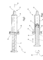
- Figures 1 to 4 is a syringe, which according to the new Process is made in its entirety with the reference number Designated 10.
- the syringe 10 is manufactured using a mounting part 12, that the later piston rod 14 and the later Backstop 16 includes. Piston rod 14 and back stop 16 are prior to final assembly of the syringe 12 to that shown in FIG. 1 Assembly part connected by material.
- the reference number 18 denotes a syringe cylinder, the one at its distal end 20 in a manner known per se Has opening 22. A cannula can be attached to the opening 22 become.
- Syringe 10 is preferred prior to final assembly filled with a drug (not shown here) and then with a piston plug 24 (Fig. 4) on the proximal Closed in late 26. This happens when bottling Drugs usually under sterile conditions in the pharmaceutical manufacturer of the drug. Completeness however, it should be noted that the present invention is for the sake of not limited to syringes for these purposes only is, but also with all other medical Syringes and also syringes for the non-medical Range can be applied.
- the piston rod 14 has one at its proximal end 28 End plate 30, which when using the syringe as a support surface for example for the thumb of the doctor.
- the actual piston rod closes on the support plate 30 at its front end into a threaded pin 32 expires.
- the piston rod 14 here in cross section cross-shaped profile, as is the case with generic syringes is known.
- the invention is not limited to this, i.e. the piston rod can also have any other profile exhibit.
- the for this the required rotary movement is shown in FIG. 4 with an arrow 34 characterized.
- the piston rod 14 guides when fastening on the piston plug 24 also a translational movement in Direction of an arrow 36. This translational movement takes place parallel and along the longitudinal axis 38 of the syringe 10. Inserting the piston rod 14 into the syringe barrel 18 is known to the relevant experts.
- the backstop 16 has in the embodiment shown here an elliptical plate 40 which is transverse to Longitudinal axis 38 of the syringe 10 and thus also across the piston rod 14 extends.
- the plate 40 is used when assembled Syringe 10 as a finger rest, and it facilitates manageability the syringe 10.
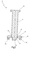
- An annular groove 42 is provided in the middle of the plate 40, which concentrically the threaded pin 32 of the piston rod 14 surrounds. As shown in Fig. 5, the groove 42 is in the mounting part 12, i.e. before the final assembly of the syringe 10, not to the bottom 44 of the plate 40. The Rather, 42 has the function of weakening the material a predetermined breaking point between the piston rod 14 and the backstop 16 represents. As explained in more detail below, the piston rod 14 and the back stop 16 at the Final assembly of the syringe 10 at this predetermined breaking point from each other separated and then represent two separate components of the Syringe 10.
- the groove 42 is along of their circumference partially up to the bottom 44 of the plate 40 executed (cannot be seen in the sectional view in FIG. 5), so that the piston rod 14 and the back stop 16 along the groove 42 to a certain extent only through small webs 46 are connected.
- This configuration allows one particularly simple and effective separation of the piston rod 14 from the back stop 16 when screwing in the piston rod 14 in reach the piston plug 24.
- the two brackets 48, 50 are on the distal end 20 of the syringe barrel 18 side of the Plate 40 two brackets 48, 50 arranged.
- the two brackets 48, 50 each consist of a U-shaped part, the with its two free legs in one piece with the plate 40 connected is.
- the two brackets 48, 50 thus each form an insertion opening 52, with the help of the back stop 16 attached to the proximal end 26 of the syringe barrel 18 can be.
- the two brackets 48, 50 are in the preferred embodiment here point-symmetrical to that Free end of the threaded pin 32 is arranged.
- the mounting part 12 designed in this way is preferably for fastening provided on syringe cylinders 18 with a so-called DIN flange.
- a DIN flange is shown in FIG. 2 with the reference number 54 designated.
- four corners, two of which are numbered 56 in FIG. 2 and 58 are designated.
- Two more corners that are symmetrical too the corners 56, 58 lie in the illustration in FIG. 2 into the insertion openings 52 of the two brackets 48, 50 and thus fix the back stop 16 to the syringe barrel 18.
- Since the DIN flange 54 is not rotationally symmetrical due to the corners 56, 58 is a bayonet-like with this configuration Locking between the back stop 16 and the Syringe barrel 18 realized.
- This type of locking is here designated overall by the reference number 60.
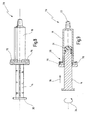
- FIGS. 6 to 9 show a second exemplary embodiment of the new syringe in its entirety with reference number 70 designated.
- the syringe 70 is made using a mounting member 72 manufactured, which is in the way of its attachment to Syringe barrel 18 differs from the mounting part 12 of FIG. 1.
- the one designated here with reference number 74 Back stop at its distal end 22 of the syringe barrel 18 facing bottom four brackets 76, which in the type of a segment ring around the threaded pin 32 of the piston rod 14 are arranged around.
- brackets 76 Snap or locking means, when the back stop is pushed open 74 on the syringe barrel 18 in the direction of the arrow 36 over the flange 78 of the syringe barrel 18.
- the Flange 78 can be a DIN flange in this embodiment be as in the previous embodiment, but also a round flange or another flange shape.
- the brackets 76 in the present Embodiment in number, more delicate and therefore more flexible executed as the brackets 48, 50 in the embodiment 1. Otherwise, the backstop 74 corresponds however, the backgauge 16 already described above.
- the syringe barrel 18, back stop 16 or 74 and piston rod 14 are made of a polymer in these exemplary embodiments Made of material. This enables the backgauge 16, 74 and the piston rod 14 in a single stage Injection molding process. Alternatively, it is possible the backgauge 16, 74 in a two-stage injection molding process molded onto the piston rod 14 so that different Materials can be used. Generally can but also other materials than polymeric materials Application, for example, the syringe barrel 18 could be made of glass.
- the piston rod 14 and the back stop 16, 74 material connected to the combined mounting part 12, 72 are the piston rod 14 and the back stop 16, 74 material connected to the combined mounting part 12, 72.
- a different connection between the backgauge and the piston rod is possible is, for example, a non-positive and / or positive Connection.
- the back stop 16, 74 have a bore through which the threaded pin 32 of the Piston rod 14 passes through, the inner diameter of the Bore is selected so that the piston rod itself only at Applying a predetermined force through the bore can slide. It can also be used to screw in the piston rod 14 intended rotary movement 34 are used to the backstop 16, 74 from a positive connection to solve with the piston rod 14.
- the backstop 16, 74 prevents not necessarily that the piston rod 14 back out of the syringe barrel 18 can be pulled out.
- the relevant specialist without The backstop 16, 74 can also do so, however be formed such that pulling out the piston plug 24 towards the proximal end 26 of the syringe barrel 18 is impossible.
- only the inside diameter is required the passage opening provided in the backgauge 16, 74 for the piston rod 14 to be smaller than that Outer diameter of the piston plug 24.
Landscapes
- Health & Medical Sciences (AREA)
- Vascular Medicine (AREA)
- Engineering & Computer Science (AREA)
- Anesthesiology (AREA)
- Biomedical Technology (AREA)
- Heart & Thoracic Surgery (AREA)
- Hematology (AREA)
- Life Sciences & Earth Sciences (AREA)
- Animal Behavior & Ethology (AREA)
- General Health & Medical Sciences (AREA)
- Public Health (AREA)
- Veterinary Medicine (AREA)
- Infusion, Injection, And Reservoir Apparatuses (AREA)
Abstract
Description
- Fig. 1
- eine Kolbenstange und einen Rückanschlag als kombiniertes Montageteil gemäß einem ersten Ausführungsbeispiel,
- Fig. 2
- eine Spritze unter Verwendung des Montageteils aus Fig. 1,
- Fig. 3
- die Spritze aus Fig. 2 in einer Seitenansicht,
- Fig. 4
- die Spritze aus Fig. 3 in einer Querschnittsansicht, wobei die Kolbenstange hier bereits weiter in den Spritzenzylinder eingeschoben ist,
- Fig. 5
- das Montageteil aus Fig. 1 in einer vergrößerten Querschnittsdarstellung entlang der Schnittlinie V-V in Fig. 1,
- Fig. 6
- ein Montageteil bestehend aus Rückanschlag und Kolbenstange gemäß einem weiteren Ausführungsbeispiel,
- Fig. 7
- eine Spritze mit dem Montageteil aus Fig. 6,
- Fig. 8
- die Spritze aus Fig. 7 in einer Seitenansicht, und
- Fig. 9
- die Spritze aus Fig. 8 in einer Querschnittsdarstellung, wobei die Kolbenstange bereits in den Spritzenzylinder eingeschoben ist.
Claims (13)
- Verfahren zum Herstellen einer Spritze (10; 70), insbesondere für medizinische Anwendungen, mit den Schritten:dadurch gekennzeichnet, dass der Rückanschlag (16; 74) vor dem Schritt c) mit der Kolbenstange (14) zu einem kombinierten Montageteil (12; 72) verbunden wird und im Schritt d) von der Kolbenstange (14) abgetrennt und am Spritzenzylinder (18) befestigt wird.a) Bereitstellen eines Spritzenzylinders (18) mit einem proximalen (26) und einem distalen (20) Ende,b) Einsetzen eines Kolbenstopfens (24) in den Spritzenzylinder (18),c) Befestigen einer Kolbenstange (14) an dem Kolbenstopfen (24), undd) Anordnen eines Rückanschlags (16; 74) am proximalen Ende (26) des Spritzenzylinders (18),
- Verfahren nach Anspruch 1, dadurch gekennzeichnet, dass der Rückanschlag (16; 74) im Schritt d) im Wesentlichen parallel zu einer Längsachse (38) des Spritzenzylinders (18) an diesen herangeführt wird.
- Verfahren nach Anspruch 1 oder 2, dadurch gekennzeichnet, dass der Rückanschlag (16; 74) mit der Kolbenstange (14) über Sollbruchstellen (46) derartig verbunden ist, dass der Rückanschlag (16; 74) beim Befestigen der Kolbenstange (14) an dem Kolbenstopfen (24) von der Kolbenstange (14) abreißt.
- Verfahren nach Anspruch 3, dadurch gekennzeichnet, dass der Rückanschlag (16; 74) in einem zumindest zweistufigen Spritzgießvorgang an die Kolbenstange (14) angeformt wird.
- Verfahren nach einem der Ansprüche 1 bis 4, dadurch gekennzeichnet, dass der Rückanschlag (16) mit einer Drehbewegung (34) von der Kolbenstange (14) getrennt wird, und zwar vorzugsweise mit einer Drehbewegung (34), mit der ferner auch die Kolbenstange (14) in den Kolbenstopfen (24) eingeschraubt wird.
- Verfahren nach einem der Ansprüche 1 bis 5, dadurch gekennzeichnet, dass der Rückanschlag (16) mit einer bajonettartigen Verriegelung (60) an dem Spritzenzylinder (18) befestigt wird, wobei die bajonettartigen Verriegelung (60) vorzugsweise zumindest eine Halterung (48, 50) aufweist, in die ein vorspringendes Teil (56, 58) eines an dem Spritzenzylinder (18) angeordneten Flansches (54) eingreift.
- Verfahren nach einem der Ansprüche 1 bis 6, dadurch gekennzeichnet, dass die Kolbenstange (14) beim Befestigen an dem Kolbenstopfen (24) eine Translationsbewegung (36) ausführt, wobei der Rückanschlag (16; 74) mit der Translationsbewegung (36) von der Kolbenstange (14) getrennt wird.
- Verfahren nach einem der Ansprüche 1 bis 7, dadurch gekennzeichnet, dass der Rückanschlag (74) mit Schnappelementen (76), die einen am Spritzenzylinder (18) angeordneten Flansch (78) umgreifen, an dem Spritzenzylinder (18) befestigt wird.
- Spritze, insbesondere für medizinische Anwendungen, mit einem Spritzenzylinder (18), einem Kolbenstopfen (24), einer daran befestigten Kolbenstange (14) und mit einem Rückanschlag (16; 74) für den Kolbenstopfen (24), wobei der Rückanschlag (16; 74) an einem proximalen Ende (26) des Spritzenzylinders (18) angeordnet ist, dadurch gekennzeichnet, dass der Rückanschlag (16; 74) und die Kolbenstange (14) als kombinierbares Montageteil (12; 72) ausgebildet sind, das getrennt an dem Spritzenzylinder (18) angeordnet ist.
- Spritze nach Anspruch 9, dadurch gekennzeichnet, dass der Rückanschlag (16; 74) und die Kolbenstange (14) jeweils Abrissstellen (64) aufweisen, die zusammen zumindest eine Sollbruchstelle (46) festlegen.
- Montageteil zum Herstellen einer Spritze, insbesondere für medizinische Anwendungen, mit einer Kolbenstange (14) für die Spritze und einem Rückanschlag (16; 74) zum Befestigen an einem Spritzenzylinder (18), dadurch gekennzeichnet, dass die Kolbenstange (14) und der Rückanschlag (16; 74) zu einem kombinierten Montageteil (12; 72) verbunden sind und zumindest eine vorbereitete Trennstelle (46) aufweisen.
- Montageteil nach Anspruch 11, dadurch gekennzeichnet, dass der Rückanschlag (16; 74) und die Kolbenstange (14) konzentrisch zueinander zu dem kombinierten Montageteil (12; 72) verbunden sind.
- Montageteil nach Anspruch 11 oder 12, dadurch gekennzeichnet, dass der Rückanschlag (16; 74) und die Kolbenstange (14) jeweils Abrissstellen (64) aufweisen, die zusammen zumindest eine Sollbruchstelle (46) festlegen.
Applications Claiming Priority (2)
| Application Number | Priority Date | Filing Date | Title |
|---|---|---|---|
| DE10326706 | 2003-06-04 | ||
| DE10326706A DE10326706A1 (de) | 2003-06-04 | 2003-06-04 | Spritze, insbesondere für medizinische Anwendungen, sowie Verfahren zum Herstellen einer solchen |
Publications (2)
| Publication Number | Publication Date |
|---|---|
| EP1484072A1 true EP1484072A1 (de) | 2004-12-08 |
| EP1484072B1 EP1484072B1 (de) | 2007-09-19 |
Family
ID=33154608
Family Applications (1)
| Application Number | Title | Priority Date | Filing Date |
|---|---|---|---|
| EP04011086A Expired - Lifetime EP1484072B1 (de) | 2003-06-04 | 2004-05-10 | Spritze sowie Verfahren zum Herstellen einer solchen |
Country Status (3)
| Country | Link |
|---|---|
| US (1) | US7951120B2 (de) |
| EP (1) | EP1484072B1 (de) |
| DE (2) | DE10326706A1 (de) |
Cited By (1)
| Publication number | Priority date | Publication date | Assignee | Title |
|---|---|---|---|---|
| EP1933726B2 (de) † | 2005-10-05 | 2013-11-20 | Orlando Da Rold | Flexible hohlwelle |
Families Citing this family (15)
| Publication number | Priority date | Publication date | Assignee | Title |
|---|---|---|---|---|
| US6830564B2 (en) * | 2002-01-24 | 2004-12-14 | Robin Scott Gray | Syringe and method of using |
| US9108007B2 (en) * | 2009-06-01 | 2015-08-18 | Sanofi-Aventis Deutschland Gmbh | Spindle and bearing combination and drug delivery device |
| JP2012016442A (ja) * | 2010-07-07 | 2012-01-26 | Oshimo Sangyo Kk | 容器 |
| US20120041388A1 (en) * | 2010-08-11 | 2012-02-16 | Farnam Companies, Inc. | Syringe handle device |
| AU2011310580C1 (en) * | 2010-10-01 | 2016-03-10 | Bracco Imaging Spa | Finger-grip device for medical syringe or cartridge |
| JP6616073B2 (ja) * | 2011-03-24 | 2019-12-04 | サノフィ−アベンティス・ドイチュラント・ゲゼルシャフト・ミット・ベシュレンクテル・ハフツング | 医療デバイスで実行可能な作動動作を検出するためのデバイス及び方法 |
| SMT202100458T1 (it) | 2014-04-14 | 2021-09-14 | Swedish Orphan Biovitrum Ab Publ | Asta di stantuffo di siringa |
| US10258502B2 (en) * | 2014-09-18 | 2019-04-16 | Orbit Biomedical Limited | Therapeutic agent delivery device |
| EP3058970A1 (de) | 2015-02-19 | 2016-08-24 | Sanofi-Aventis Deutschland GmbH | Datensammlungsvorrichtung zur Befestigung an einer Injektionsvorrichtung |
| USD812223S1 (en) | 2015-05-18 | 2018-03-06 | West Pharmaceutical Services, Inc. | Finger flange |
| JP6901975B2 (ja) | 2015-06-09 | 2021-07-14 | サノフィ−アベンティス・ドイチュラント・ゲゼルシャフト・ミット・ベシュレンクテル・ハフツング | 注射デバイスに取り付けられるデータ収集装置 |
| EP3313476B1 (de) * | 2015-06-25 | 2019-08-21 | Merck Sharp & Dohme B.V. | Anschlag für eine spritze |
| USD790691S1 (en) * | 2015-07-28 | 2017-06-27 | West Pharmaceutical Services, Inc. | Finger flange |
| US10596321B2 (en) * | 2016-04-08 | 2020-03-24 | Allergan, Inc. | Aspiration and injection device |
| US10537683B2 (en) | 2016-11-03 | 2020-01-21 | Johnson & Johnson Surgical Vision, Inc. | Syringe finger grip |
Citations (3)
| Publication number | Priority date | Publication date | Assignee | Title |
|---|---|---|---|---|
| DE3107414A1 (de) * | 1981-02-27 | 1982-09-16 | B. Braun Melsungen Ag, 3508 Melsungen | Einmalspritze fuer den medizinischen gebrauch |
| EP0764450A1 (de) * | 1995-09-22 | 1997-03-26 | Becton, Dickinson and Company | Eine Arretiervorrichtung für eine Spritze ohne Flansch |
| JP2003199827A (ja) * | 2001-12-28 | 2003-07-15 | Terumo Corp | シリンジ |
Family Cites Families (14)
| Publication number | Priority date | Publication date | Assignee | Title |
|---|---|---|---|---|
| US3084688A (en) * | 1959-07-15 | 1963-04-09 | Robert K Mcconnaughey | Disposable hypodermic syringe |
| AR243387A1 (es) | 1991-10-03 | 1993-08-31 | Cesar Gabriel Corsich | Jeringa hipodermica con embolo trabable para evitar su recarga y reutilizacion. |
| US5380295A (en) | 1992-12-14 | 1995-01-10 | Mallinckrodt Medical, Inc. | Delivery apparatus with mechanism preventing rearward movement of a piston disposed therein |
| DE4331137A1 (de) | 1993-05-06 | 1994-11-10 | Becton Dickinson Co | Spritze für medizinische Zwecke |
| DE9321547U1 (de) | 1993-05-06 | 1999-07-15 | Becton Dickinson And Co., Franklin Lakes, N.J. | Spritze für medzinische Zwecke |
| DE4318142C2 (de) * | 1993-06-02 | 1995-07-06 | Richard Herbst | Lanzettenvorrichtung zur Vorbereitung einer Blutentnahme |
| DE4434644C2 (de) | 1994-09-28 | 1997-08-07 | Schott Glaswerke | Behältnis zur Lagerung und Verabreichung von Injektions-, Infusions- und Diagnostikpräparaten |
| US5667495A (en) | 1995-04-21 | 1997-09-16 | Becton Dickinson France S.A. | Backstop device for a syringe |
| EP0864372B1 (de) * | 1997-03-14 | 2002-12-04 | Sun Medical Co., Ltd. | Behälter zur Abgabe von Tröpfen |
| US5876379A (en) * | 1998-01-22 | 1999-03-02 | Alcon Laboratories, Inc. | Syringe cannula holder |
| JP2002515268A (ja) | 1998-04-30 | 2002-05-28 | アボット・ラボラトリーズ | 注射器アセンブリ |
| WO2000007648A1 (en) | 1998-08-06 | 2000-02-17 | Schott Pharmaceutical Packaging, Inc. | Prefilled syringe with means for preventing plunger removal |
| DE19929325A1 (de) | 1999-06-26 | 2001-01-18 | Vetter & Co Apotheker | Spritze für medizinische Zwecke |
| JP4227287B2 (ja) | 2000-05-19 | 2009-02-18 | 株式会社大協精工 | 医薬品用容器兼注射器用ピストン離脱防止ストッパー |
-
2003
- 2003-06-04 DE DE10326706A patent/DE10326706A1/de not_active Ceased
-
2004
- 2004-05-10 DE DE502004004995T patent/DE502004004995D1/de not_active Expired - Lifetime
- 2004-05-10 EP EP04011086A patent/EP1484072B1/de not_active Expired - Lifetime
- 2004-05-17 US US10/847,101 patent/US7951120B2/en not_active Expired - Fee Related
Patent Citations (3)
| Publication number | Priority date | Publication date | Assignee | Title |
|---|---|---|---|---|
| DE3107414A1 (de) * | 1981-02-27 | 1982-09-16 | B. Braun Melsungen Ag, 3508 Melsungen | Einmalspritze fuer den medizinischen gebrauch |
| EP0764450A1 (de) * | 1995-09-22 | 1997-03-26 | Becton, Dickinson and Company | Eine Arretiervorrichtung für eine Spritze ohne Flansch |
| JP2003199827A (ja) * | 2001-12-28 | 2003-07-15 | Terumo Corp | シリンジ |
Non-Patent Citations (1)
| Title |
|---|
| PATENT ABSTRACTS OF JAPAN vol. 2003, no. 11 5 November 2003 (2003-11-05) * |
Cited By (1)
| Publication number | Priority date | Publication date | Assignee | Title |
|---|---|---|---|---|
| EP1933726B2 (de) † | 2005-10-05 | 2013-11-20 | Orlando Da Rold | Flexible hohlwelle |
Also Published As
| Publication number | Publication date |
|---|---|
| US7951120B2 (en) | 2011-05-31 |
| US20040254539A1 (en) | 2004-12-16 |
| EP1484072B1 (de) | 2007-09-19 |
| DE502004004995D1 (de) | 2007-10-31 |
| DE10326706A1 (de) | 2005-01-05 |
Similar Documents
| Publication | Publication Date | Title |
|---|---|---|
| DE60024202T2 (de) | Herstellungsmethode einer Spritze mit einziehbarer Nadel | |
| DE60019446T2 (de) | Flüssigkeitstransferset für phiolen und andere medizinische behälter | |
| EP1410819B1 (de) | Originalitätsverschluss für eine Spritze | |
| EP1484072B1 (de) | Spritze sowie Verfahren zum Herstellen einer solchen | |
| DE69622949T2 (de) | Eine Arretiervorrichtung für eine Spritze | |
| EP0912209B1 (de) | Injektionsspritzenkopf mit originalitätsverschluss | |
| DE60028423T2 (de) | Spritze mit zurückziehbarer Nadel | |
| EP1566194B1 (de) | Spritze, insbesondere für medizinische Anwendungen | |
| WO2012116790A1 (de) | Verschluss für eine spritze und herstellungsverfahren | |
| CH691031A5 (de) | Zweiteilige Vorrichtung für die Verabreichung von Arzneimitteln. | |
| EP1566195A1 (de) | Anordnung zum Lagern, Transportieren und Applizieren einer vorzugsweise medizinischen Flüssigkeit | |
| EP1658107A1 (de) | Vorrichtung zur injektion eines injizierbaren produktes | |
| EP0438453B1 (de) | Injektionsvorrichtung mit originalitätssicherungsvorrichtung | |
| EP2089084B1 (de) | Aufsatz für eine spritze oder eine karpule | |
| EP3638357B1 (de) | Spritze mit luer-lock-anschluss | |
| WO2000040284A1 (de) | Injektionsspritze | |
| WO2010091522A2 (de) | Verabreichungsvorrichtung, insbesondere autoinjektionsvorrichtung, für eine medizinische substanz mit einer abzugshilfe für eine schutzkappe | |
| WO2010085903A1 (de) | Verabreichungsvorrichtung mit halteelement für fluidbehälter | |
| DE69913324T2 (de) | Einwegspritze | |
| DE102016118767A1 (de) | Verfahren zum Herstellen einer Spritze mit einem integrierten Verschlusselement | |
| DE102015107631A1 (de) | Spritze mit Verschluss | |
| EP4419173A1 (de) | Verschluss für einen medizinischen hohlkörper, medizinischer hohlkörper mit einem solchen verschluss und verfahren zur herstellung eines solchen verschlusses | |
| WO2010075920A1 (de) | Karpulenspritze mit einer injektionskanüle und einer durchstechkanüle | |
| DE202013011561U1 (de) | Verschluss-System, insbesondere Spritzenverschluss und Behälter fürpharmazeutische Präparate, insbesondere Spritze für medizinische Zwecke | |
| EP4648827A1 (de) | Ampulle mit originalitätsverschluss und verschlusskappe für eine solche ampulle |
Legal Events
| Date | Code | Title | Description |
|---|---|---|---|
| PUAI | Public reference made under article 153(3) epc to a published international application that has entered the european phase |
Free format text: ORIGINAL CODE: 0009012 |
|
| AK | Designated contracting states |
Kind code of ref document: A1 Designated state(s): AT BE BG CH CY CZ DE DK EE ES FI FR GB GR HU IE IT LI LU MC NL PL PT RO SE SI SK TR |
|
| AX | Request for extension of the european patent |
Extension state: AL HR LT LV MK |
|
| 17P | Request for examination filed |
Effective date: 20050204 |
|
| AKX | Designation fees paid |
Designated state(s): DE FR GB IT |
|
| GRAP | Despatch of communication of intention to grant a patent |
Free format text: ORIGINAL CODE: EPIDOSNIGR1 |
|
| GRAS | Grant fee paid |
Free format text: ORIGINAL CODE: EPIDOSNIGR3 |
|
| GRAA | (expected) grant |
Free format text: ORIGINAL CODE: 0009210 |
|
| AK | Designated contracting states |
Kind code of ref document: B1 Designated state(s): DE FR GB IT |
|
| REG | Reference to a national code |
Ref country code: GB Ref legal event code: FG4D Free format text: NOT ENGLISH |
|
| REF | Corresponds to: |
Ref document number: 502004004995 Country of ref document: DE Date of ref document: 20071031 Kind code of ref document: P |
|
| ET | Fr: translation filed | ||
| GBT | Gb: translation of ep patent filed (gb section 77(6)(a)/1977) |
Effective date: 20071227 |
|
| PLBE | No opposition filed within time limit |
Free format text: ORIGINAL CODE: 0009261 |
|
| STAA | Information on the status of an ep patent application or granted ep patent |
Free format text: STATUS: NO OPPOSITION FILED WITHIN TIME LIMIT |
|
| 26N | No opposition filed |
Effective date: 20080620 |
|
| PGFP | Annual fee paid to national office [announced via postgrant information from national office to epo] |
Ref country code: IT Payment date: 20100519 Year of fee payment: 7 |
|
| PGFP | Annual fee paid to national office [announced via postgrant information from national office to epo] |
Ref country code: GB Payment date: 20100519 Year of fee payment: 7 |
|
| PGFP | Annual fee paid to national office [announced via postgrant information from national office to epo] |
Ref country code: FR Payment date: 20110607 Year of fee payment: 8 |
|
| PGFP | Annual fee paid to national office [announced via postgrant information from national office to epo] |
Ref country code: DE Payment date: 20110520 Year of fee payment: 8 |
|
| GBPC | Gb: european patent ceased through non-payment of renewal fee |
Effective date: 20110510 |
|
| PG25 | Lapsed in a contracting state [announced via postgrant information from national office to epo] |
Ref country code: IT Free format text: LAPSE BECAUSE OF NON-PAYMENT OF DUE FEES Effective date: 20110510 |
|
| PG25 | Lapsed in a contracting state [announced via postgrant information from national office to epo] |
Ref country code: GB Free format text: LAPSE BECAUSE OF NON-PAYMENT OF DUE FEES Effective date: 20110510 |
|
| REG | Reference to a national code |
Ref country code: FR Ref legal event code: ST Effective date: 20130131 |
|
| REG | Reference to a national code |
Ref country code: DE Ref legal event code: R119 Ref document number: 502004004995 Country of ref document: DE Effective date: 20121201 |
|
| PG25 | Lapsed in a contracting state [announced via postgrant information from national office to epo] |
Ref country code: FR Free format text: LAPSE BECAUSE OF NON-PAYMENT OF DUE FEES Effective date: 20120531 |
|
| PG25 | Lapsed in a contracting state [announced via postgrant information from national office to epo] |
Ref country code: DE Free format text: LAPSE BECAUSE OF NON-PAYMENT OF DUE FEES Effective date: 20121201 |