EP0912209B1 - Injektionsspritzenkopf mit originalitätsverschluss - Google Patents
Injektionsspritzenkopf mit originalitätsverschluss Download PDFInfo
- Publication number
- EP0912209B1 EP0912209B1 EP97929272A EP97929272A EP0912209B1 EP 0912209 B1 EP0912209 B1 EP 0912209B1 EP 97929272 A EP97929272 A EP 97929272A EP 97929272 A EP97929272 A EP 97929272A EP 0912209 B1 EP0912209 B1 EP 0912209B1
- Authority
- EP
- European Patent Office
- Prior art keywords
- cannula
- guide
- sealing disk
- syringe head
- guide grooves
- Prior art date
- Legal status (The legal status is an assumption and is not a legal conclusion. Google has not performed a legal analysis and makes no representation as to the accuracy of the status listed.)
- Expired - Lifetime
Links
Images

Classifications
-
- A—HUMAN NECESSITIES
- A61—MEDICAL OR VETERINARY SCIENCE; HYGIENE
- A61M—DEVICES FOR INTRODUCING MEDIA INTO, OR ONTO, THE BODY; DEVICES FOR TRANSDUCING BODY MEDIA OR FOR TAKING MEDIA FROM THE BODY; DEVICES FOR PRODUCING OR ENDING SLEEP OR STUPOR
- A61M5/00—Devices for bringing media into the body in a subcutaneous, intra-vascular or intramuscular way; Accessories therefor, e.g. filling or cleaning devices, arm-rests
- A61M5/178—Syringes
- A61M5/28—Syringe ampoules or carpules, i.e. ampoules or carpules provided with a needle
- A61M5/285—Syringe ampoules or carpules, i.e. ampoules or carpules provided with a needle with sealing means to be broken or opened
- A61M5/288—Syringe ampoules or carpules, i.e. ampoules or carpules provided with a needle with sealing means to be broken or opened by piercing without internal pressure increase
-
- A—HUMAN NECESSITIES
- A61—MEDICAL OR VETERINARY SCIENCE; HYGIENE
- A61M—DEVICES FOR INTRODUCING MEDIA INTO, OR ONTO, THE BODY; DEVICES FOR TRANSDUCING BODY MEDIA OR FOR TAKING MEDIA FROM THE BODY; DEVICES FOR PRODUCING OR ENDING SLEEP OR STUPOR
- A61M5/00—Devices for bringing media into the body in a subcutaneous, intra-vascular or intramuscular way; Accessories therefor, e.g. filling or cleaning devices, arm-rests
- A61M5/178—Syringes
- A61M5/31—Details
- A61M5/32—Needles; Details of needles pertaining to their connection with syringe or hub; Accessories for bringing the needle into, or holding the needle on, the body; Devices for protection of needles
- A61M5/3202—Devices for protection of the needle before use, e.g. caps
-
- A—HUMAN NECESSITIES
- A61—MEDICAL OR VETERINARY SCIENCE; HYGIENE
- A61M—DEVICES FOR INTRODUCING MEDIA INTO, OR ONTO, THE BODY; DEVICES FOR TRANSDUCING BODY MEDIA OR FOR TAKING MEDIA FROM THE BODY; DEVICES FOR PRODUCING OR ENDING SLEEP OR STUPOR
- A61M5/00—Devices for bringing media into the body in a subcutaneous, intra-vascular or intramuscular way; Accessories therefor, e.g. filling or cleaning devices, arm-rests
- A61M5/178—Syringes
- A61M5/31—Details
- A61M2005/3117—Means preventing contamination of the medicament compartment of a syringe
- A61M2005/3118—Means preventing contamination of the medicament compartment of a syringe via the distal end of a syringe, i.e. syringe end for mounting a needle cannula
- A61M2005/312—Means preventing contamination of the medicament compartment of a syringe via the distal end of a syringe, i.e. syringe end for mounting a needle cannula comprising sealing means, e.g. severable caps, to be removed prior to injection by, e.g. tearing or twisting
-
- A—HUMAN NECESSITIES
- A61—MEDICAL OR VETERINARY SCIENCE; HYGIENE
- A61M—DEVICES FOR INTRODUCING MEDIA INTO, OR ONTO, THE BODY; DEVICES FOR TRANSDUCING BODY MEDIA OR FOR TAKING MEDIA FROM THE BODY; DEVICES FOR PRODUCING OR ENDING SLEEP OR STUPOR
- A61M5/00—Devices for bringing media into the body in a subcutaneous, intra-vascular or intramuscular way; Accessories therefor, e.g. filling or cleaning devices, arm-rests
- A61M5/50—Devices for bringing media into the body in a subcutaneous, intra-vascular or intramuscular way; Accessories therefor, e.g. filling or cleaning devices, arm-rests having means for preventing re-use, or for indicating if defective, used, tampered with or unsterile
- A61M5/5086—Devices for bringing media into the body in a subcutaneous, intra-vascular or intramuscular way; Accessories therefor, e.g. filling or cleaning devices, arm-rests having means for preventing re-use, or for indicating if defective, used, tampered with or unsterile for indicating if defective, used, tampered with or unsterile
Definitions
- the invention relates to an injection syringe head Tamper-evident closure for a syringe barrel, the one Has cylinder neck, which with an axial fluid outlet channel and a peripheral bead for anchoring the hypodermic syringe head is provided with an injection cannula, which is mounted in a cannula holder from which it is attached protrudes both axial ends and that in a cannula carrier guide is arranged movable relative to this, and one Cannula protection cap, to which a predetermined breaking point Cannula carrier guide more firmly on the circumferential bead of the cylinder neck Anchoring part that can be fixed under elastic deformation connects with a washer, the Cannula protection cap on the inner circumference in the axial direction Has ribs, which with corresponding ribs of the cannula holder are engaged for a rotary drive of the same.
- Such an injection syringe head is to be closed so-called pre-filled syringes, i.e. of syringes with filled with a liquid medicine and with an injection cannula provided sterile packed and offered ready for use become. It is essential that these pre-filled syringes with a Tamper-evident seal that allows to recognize whether the syringe is still filled with the original filling and is sterile.
- the hypodermic syringe head should have enough cannula protect it so that when the syringe head is assembled No damage or contamination on the syringe barrel the cannula can come. It is also for mass production a simple construction of the injection syringe is required.
- the invention aims to provide an injection syringe head to create that in conjunction with conventional syringe barrels a pre-filled syringe that is not only simple and assembled under sterile conditions and with a tamper-evident seal can be provided, but at the same time Measures are taken to correct operating errors with those discussed to avoid adverse consequences.
- the invention relates to an injection syringe head with tamper-evident closure for a syringe barrel, the one Has cylinder neck, which with an axial fluid outlet channel and a peripheral bead for anchoring the Injection syringe head is provided with an injection cannula, which is mounted in a cannula holder from which it is attached protrudes both axial ends and that in a cannula carrier guide is arranged movable relative to this, and one Cannula protection cap, to which a predetermined breaking point Cannula carrier guide more firmly on the circumferential bead of the cylinder neck Anchoring part that can be fixed under elastic deformation connects with a washer, the Cannula protection cap on the inner circumference in the axial direction Has ribs, which with corresponding ribs of the cannula holder are engaged for a rotary drive, wherein on the circumference of the cannula holder two axially symmetrical, with predetermined slope substantially V-
- the injection syringe head constructed according to the invention exists only from four assembly parts, etc. the protective cap with anchoring part, the sealing washer, the cannula carrier guide and the cannula holder with cannula (glued or HF-welded), and is therefore easy to manufacture and assemble.
- the via a predetermined breaking point with the anchoring part connected protective cap ensures the tamper-evident function.
- the cannula is protected and integrated in the syringe head, and in the final assembly, the entire syringe head is included all four assembly parts as one unit on the syringe barrel put on so that there is no damage or The injection cannula can become contaminated. After this Attaching the syringe head can fill the syringe barrel and sealed with a corresponding piston unit become.
- the syringe is activated by turning the Protective cap, which breaks the predetermined breaking point and the cannula holder is screwed into the cannula holder guide, etc. with any direction of rotation.
- the cannula moves relatively to the sealing washer, thereby preventing the drug from entering into the cannula.
- the protective cap is then in withdrawn axially and the syringe is ready for injection ready.
- the guide grooves according to the invention on the circumference of the cannula carrier guide ensure that the protective cap is out of its unactuated Position, i.e. if the predetermined breaking point is still intact, for actuating the syringe head in both directions of rotation can be rotated, thereby screwing in the cannula holder into the cannula carrier guide.
- Accidental Twisting of the protective cap while opening the predetermined breaking point, without the injection cannula being brought into the active position would be excluded.
- inventive Training the guide groove of the assembly facilitated.
- the training according to the invention thus offers an optimal Sterility with reliable operation in both directions of rotation.
- the slope hit the guide grooves so that about a 1/4 turn of the Cannula carrier a path of the cannula relative to the sealing washer of about 3 mm. This way ensures that after about a 1/4 turn while simultaneously destroying the Tamper-evident closure of the cannula protection cap the cannula has penetrated far through the sealing washer that the lateral Inlet opening of the cannula becomes free and the medication after removing the already twisted cannula protective cap can be sprayed freely.
- the anchoring of the injection syringe head to the syringe barrel can be achieved by pressing or a snap connection become.
- the latter option is preferably used in which case the anchoring part is made of elastic material and snapped onto the circumferential bead of the cylinder neck becomes.
- Another preferred feature of the invention is in that the anchoring part is conical on the inside is, the cannula carrier guide in the anchoring part of the distal end of which is pressed in. The press fit relieved and speeds up the assembly of the pre-filled syringe.
- the assembly of the pre-filled syringe can be further simplified, if according to a preferred feature of the invention on the Inside the anchoring part an annular groove for receiving the Sealing washer is provided during assembly. This can the injection syringe head is transported in the fully assembled state, to be sterilized and temporarily stored before placed on prepared syringe barrel plunger units becomes.
- a major advantage of the invention is that the drug is not activated until the pre-filled syringe is activated, unscrewing the tamper-evident seal and removing it the cannula protection cap in contact with the inside of the cannula is coming. In this way, the drug crystallizes out in the cannula, during the often very long storage period the syringes, and the associated clogging of the cannula avoided. Due to the described separation between the drug and the pre-filled syringe closure system ensures sterility even over a long period of time. The pre-filled syringe therefore does not have to be added after manufacture can be packed aseptically, but without additional packaging be packed in boxes.
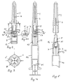
- the injection syringe head settles according to FIGS. 1 and 2 essentially composed of four assembly parts, etc. one Protective cap 1, which is integral with a predetermined breaking point 2 an anchoring part 3 is connected, an injection cannula 4, which is firmly anchored in a cannula holder 5, e.g. by High frequency welding or gluing, a cannula carrier guide 6 and a sealing washer 7.
- the cannula holder 5 in cross-section with four ribs 8 formed between which radial ribs 1 'of the cannula protective cap 1 protrude.
- the Cannula holder 5 When assembling the injection syringe head, the Cannula holder 5 inserted so far into the cannula holder guide 6 until the end 4 'of the cannula 4 from the cannula carrier guide 6 protrudes on the side of the sealing washer 7.
- the cannula holder guide 6 is then in the anchoring part 3 and inserted into the protective cap 1 from its free end (Fig. 1), with a conical design of the outer circumference the cannula support guide 6 and a corresponding conical Formation of the inner wall of the anchoring part 3 a at least non-positive press fit is achieved.
- the sealing washer 7 is inserted into the anchoring part 3 and snaps into an annular groove 10 on the inner circumference of the anchoring part 3 a.
- the injection syringe head completed in this way is shown in Fig. 2 and can be transported, can be sterilized and stored temporarily without the risk contamination or damage to the injection cannula 4 consists.
- the sealing washer shown in FIGS. 1 and 2 and 2a 7 forms a membrane 7 'in its central area.
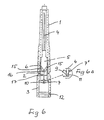
- the end 4 'of the injection cannula facing the sealing disk 7 4 is sharpened or closed at 9 according to FIG. 6 and provided with a side opening 11.
- the injection cannula interacts with a sealing washer 7, which in its central area with a membrane 7 ' which is provided by the cannula when activating the syringe is punctured.
- a sealing washer 7 which in its central area with a membrane 7 ' which is provided by the cannula when activating the syringe is punctured.
- the sealing washer 7 and the closed end of the Cannula closes the 7 "hole, which is flared upwards before activating the syringe.
- the anchoring part 3 is made of elastic material and with a circumferential groove 12 on a circumferential bead 13 of the Cylinder neck of the syringe barrel 14 can be snapped on.
- the anchoring part 3 on the cylinder neck of the Syringe barrel 14 pressed or by ultrasound or High-frequency deformation can be molded.
- the syringe barrel 14 is filled with a drug and by inserting one Piston unit K sealed. The completed syringe assembly is then ready for use.
- the cannula holder is used to initiate the injection process 5 with the injection cannula 4 by unscrewing the protective cap 1 in the cannula carrier guide 6 in any direction screwed in such that the sealing washer according to FIGS. 1 to 5 7 is pierced or, according to FIG. 6, the opening 11 of the Cannula 4 passes the sealing washer 7 to a sufficient extent has to get into the area of liquid medication.
- the protective cap 1 on its inner circumference with the four ribs 1 'provided, which in the grooves of the cannula holder or engage between its arms 8 (Fig. 3).
- the cannula holder 5 has two guide grooves on its circumference 15, which is axially symmetrical with a predetermined slope essentially V-shaped.
- the guide grooves 15 open their end facing the sealing washer 7 into one another.
- a guide pin 16 of the cannula carrier guide 6 engages, the when plugging the cannula holder and cannula holder guide via an insertion groove 17 of the cannula holder, which is in radial direction extended towards its entry end, in the Mouth area 15 is introduced.
- a rotation of the protective cap 1 clockwise or counterclockwise causes this way a passage of the end 4 'of the injection cannula 4 through the sealing washer 7 or an entry of the end 9 the cannula into the syringe barrel.
- the slope of the guide grooves 15 is chosen so that e.g. with 1/4 turn of the cannula holder 5 a path of the cannula 4 relative to the sealing washer 7 of e.g. 3 mm is achieved. This path is sufficient for the Cannula cap 1 twisted off the anchoring part 3 and the Sealing washer 7 is passed safely, so that the drug through the central opening or the lateral opening 11 of the Enter cannula 4 into the cannula cavity and be injected can.
- the protective cap 1 with anchoring part 3, the cannula holder 5 and the cannula carrier guide 6 are preferably injection molded Plastic parts.
Landscapes
- Health & Medical Sciences (AREA)
- Vascular Medicine (AREA)
- Engineering & Computer Science (AREA)
- Anesthesiology (AREA)
- Biomedical Technology (AREA)
- Heart & Thoracic Surgery (AREA)
- Hematology (AREA)
- Life Sciences & Earth Sciences (AREA)
- Animal Behavior & Ethology (AREA)
- General Health & Medical Sciences (AREA)
- Public Health (AREA)
- Veterinary Medicine (AREA)
- Infusion, Injection, And Reservoir Apparatuses (AREA)
Description
Claims (4)
- Injektionsspritzenkopf mit Originalitätsverschluß für einen Spritzenzylinder (14), der einen Zylinderhals aufweist, welcher mit einem axialen Flüssigkeitsaustrittskanal und einem Umfangswulst (13) zur Verankerung des Injektionsspritzenkopfes versehen ist, mit einer Injektionskanüle (4), die in einem Kanülenträger (5) montiert ist, aus dem sie an beiden axialen Enden herausragt und der in einer Kanülenträgerführung (6) relativ zu dieser bewegbar angeordnet ist, und einer Kanülenschutzkappe (1), an die über eine Sollbruchstelle ein die Kanülenträgerführung (6) festhaltender, am Umfangswulst (12) des Zylinderhalses unter elastischer Verformung festlegbarer Verankerungsteil (3) mit einer Dichtungsscheibe anschließt, wobei die Kanülenschutzkappe (1) am Innenumfang in Axialrichtung verlaufende Rippen (1') aufweist, welche mit entsprechenden Rippen (8) des Kanülenträgers (5) für einen Drehantrieb desselben in Eingriff stehen, wobei am Umfang des Kanülenträgers (5) zwei axialsymmetrisch, mit vorbestimmter Steigung im wesentlichen V-förmig verlaufende und an ihrem der Dichtungsscheibe (7) zugekehrten Ende ineinandermündendc Führungsnuten (15) für einen im Inneren der Kanülenträgerführung (6) vorgesehenen Führungszapfen (16) ausgebildet sind, der im unbetätigten Zustand des Injektionsspritzenkopfes in den der Dichtungsscheibe (7) zugekehrten Mündungsbereich (15') der Führungsnuten (15) eingreift und bei einer Drehung der Kanülenschutzkappe (1) in jeder der beiden Drehrichtungen unter Zerstörung der Sollbruchstelle (2) relativ zu einer der beiden Führungsnuten gleitet, so daß der Kanülenträger gedreht und mit der Kanüle (4) relativ zur Dichtungsscheibe (7) bewegt wird, wobei an den der Dichtungsscheibe (7) zugekehrten Mündungsbereich (15') der Führungsnuten (15) eine nach unten offene axiale Einführnut (17) für den Führungszapfen (16) anschließt, die sich in radialer Richtung gegen ihr Eintrittsende zu erweitert, wobei das der Dichtungsscheibe (7) zugekehrte Ende (9) der Injektionskanüle (4) geschlossen und mit einer seitlichen Öffnung (11) versehen ist, durch welche das Medikament nach dem Aktivieren des Spritzenkopfes in die Kanüle eintreten kann, und wobei die Dichtungsscheibe (7') vorgelocht ist und die Injektionskanüle (4) das Loch im unbetätigten Zustand des Injektionsspritzenkopfes verschließt.
- Injektionsspritzenkopf nach Anspruch 1, dadurch gekennzeichnet, daß die Steigung der Führungsnuten (15) so getroffen ist, daß eine 1/4 Umdrehung des Kanülenträgers (5) einen Weg der Kanüle (4) relativ zur Dichtungsscheibe (7) von 3 mm bewirkt.
- Injektionsspritzenkopf nach Anspruch 1 oder 2, dadurch gekennzeichnet, daß der Verankerungsteil (3) innenseitig konisch ausgebildet und die Kanülenträgerführung (6) in den Verankerungsteil (3) von dessen offenen Ende her einpreßbar ist.
- Injektionsspritzenkopf nach einem der Ansprüche 1 bis 3, dadurch gekennzeichnet, daß an der Innenseite des Verankerungsteiles (3) eine Ringnut (10) zur Aufnahme der Dichtungsscheibe (7, 7') vorgesehen ist.
Applications Claiming Priority (4)
| Application Number | Priority Date | Filing Date | Title |
|---|---|---|---|
| AT112296 | 1996-06-25 | ||
| AT1122/96 | 1996-06-25 | ||
| AT0112296A AT404430B (de) | 1996-06-25 | 1996-06-25 | Injektionsspritzenkopf mit originalitätsverschluss |
| PCT/EP1997/003296 WO1997049444A1 (de) | 1996-06-25 | 1997-06-24 | Injektionsspritzenkopf mit originalitätsverschluss |
Publications (2)
| Publication Number | Publication Date |
|---|---|
| EP0912209A1 EP0912209A1 (de) | 1999-05-06 |
| EP0912209B1 true EP0912209B1 (de) | 2000-04-12 |
Family
ID=3507065
Family Applications (1)
| Application Number | Title | Priority Date | Filing Date |
|---|---|---|---|
| EP97929272A Expired - Lifetime EP0912209B1 (de) | 1996-06-25 | 1997-06-24 | Injektionsspritzenkopf mit originalitätsverschluss |
Country Status (7)
| Country | Link |
|---|---|
| US (1) | US6053892A (de) |
| EP (1) | EP0912209B1 (de) |
| JP (1) | JP4306801B2 (de) |
| AT (2) | AT404430B (de) |
| AU (1) | AU3343797A (de) |
| DE (1) | DE59701443D1 (de) |
| WO (1) | WO1997049444A1 (de) |
Cited By (1)
| Publication number | Priority date | Publication date | Assignee | Title |
|---|---|---|---|---|
| DE102005054075A1 (de) * | 2005-11-12 | 2007-05-16 | Vetter & Co Apotheker | Kanülenaufsatz für eine Spritze oder Karpule |
Families Citing this family (27)
| Publication number | Priority date | Publication date | Assignee | Title |
|---|---|---|---|---|
| US7798993B2 (en) * | 1998-07-29 | 2010-09-21 | Becton, Dickinson And Company | Single use syringe |
| US8202257B2 (en) * | 1998-07-29 | 2012-06-19 | Becton, Dickinson And Company | Splatter prevention mechanism for a syringe |
| US6346094B2 (en) * | 1998-09-28 | 2002-02-12 | Becton, Dickinson And Company | Pen needle magazine |
| DE19915272A1 (de) * | 1999-04-03 | 2000-10-05 | Vetter & Co Apotheker | Spritze für medizinische Zwecke |
| FR2814371B1 (fr) * | 2000-06-06 | 2002-12-06 | Wu Shun Huang | Seringue de securite avec un fourreau d'aiguille |
| KR100361377B1 (ko) * | 2000-10-20 | 2002-11-23 | 우 순 황 | 니들 슬리브를 가진 안전 주사기 |
| US6796957B2 (en) * | 2001-07-10 | 2004-09-28 | Myocardial Therapeutics, Inc. | Sterile aspiration/reinjection systems |
| AT410897B (de) * | 2002-01-09 | 2003-08-25 | Pickhard Brigitte | Injektionsspritzenkopf mit originalitätsverschluss |
| FR2839892B1 (fr) * | 2002-05-27 | 2005-03-18 | Mb Innovation | Dispositif d'injection a usage unique destine a etre pre-rempli |
| DE10316127A1 (de) * | 2003-04-09 | 2004-11-04 | Arzneimittel Gmbh Apotheker Vetter & Co. Ravensburg | Vorgefüllte Spritze oder Karpule für medizinische Zwecke |
| US8672892B2 (en) * | 2003-04-22 | 2014-03-18 | Smiths Medical Asd, Inc. | Tamper evident vacuum tube holder assembly and needle hub assembly therefor |
| EP1629857A1 (de) * | 2004-08-30 | 2006-03-01 | Fu-Yu Hsu | Spritze mit zurückziehbarer Nadel |
| US8043300B2 (en) * | 2005-07-05 | 2011-10-25 | Alcon, Inc. | Handpiece tip assembly |
| AT505616B1 (de) | 2008-02-07 | 2009-03-15 | Pickhard Brigitte | Injektionsspritze |
| KR200459145Y1 (ko) | 2009-04-07 | 2012-03-21 | 유한회사 신신프락콘 | 안전마개가 부착된 주사기형 약품용기 |
| US20130174518A1 (en) * | 2010-09-24 | 2013-07-11 | Terumo Kabushiki Kaisha | Method of assembling medicament injection device |
| GB2484490A (en) * | 2010-10-12 | 2012-04-18 | Owen Mumford Ltd | Frangible needle shield for syringe |
| AT511259A3 (de) * | 2011-02-23 | 2012-12-15 | Pharma Consult Ges M B H & Co Nfg Kg | Injektionsspritzenkopf, auspresseinheit sowie daraus gebildete injektionsspritze |
| AT511210B1 (de) * | 2011-02-23 | 2012-10-15 | Pharma Consult Gmbh & Co Nfg Kg | Injektionsspritzenkopf für eine injektionsspritze |
| WO2013038887A1 (ja) * | 2011-09-14 | 2013-03-21 | テルモ株式会社 | 液体注入器具 |
| WO2014075685A2 (en) * | 2012-11-13 | 2014-05-22 | IN.TOOL ApS | Protective cap for a device |
| DE102014008610A1 (de) * | 2014-06-06 | 2015-12-17 | Kocher-Plastik Maschinenbau Gmbh | Abgabevorrichtung |
| US20180110932A1 (en) | 2015-04-29 | 2018-04-26 | Novo Nordisk A/S | Cap Needle Assembly for an Injection Device with Predetermined Breaking Point |
| LT3651844T (lt) * | 2017-07-12 | 2023-07-25 | Hollister Incorporated | Paruoštas naudoti šlapimo kateterio rinkinys |
| CN113242743A (zh) * | 2018-12-19 | 2021-08-10 | 赛诺菲 | 用于注射装置的塑料初级包装 |
| CN116018166A (zh) * | 2020-07-30 | 2023-04-25 | 科斯卡家族有限公司 | 用于预填充医疗输送组件的系统和方法 |
| US20240269394A1 (en) * | 2023-02-14 | 2024-08-15 | Dali Medical Devices Ltd | Device for providing container closure integrity and methods of use thereof |
Family Cites Families (6)
| Publication number | Priority date | Publication date | Assignee | Title |
|---|---|---|---|---|
| US3333682A (en) * | 1965-08-18 | 1967-08-01 | Burron Medical Prod Inc | Disposable needle container |
| WO1986003126A1 (en) * | 1984-11-21 | 1986-06-05 | Ewald Pickhard | Injection syringe |
| US4820275A (en) * | 1987-12-21 | 1989-04-11 | Habley Medical Technology Corporation | Retractable needle syringe with integral spring |
| US5250037A (en) * | 1992-12-18 | 1993-10-05 | Becton, Dickinson And Company | Syringe having needle isolation features |
| US5540666A (en) * | 1993-03-31 | 1996-07-30 | Immuno Aktiengesellschaft | Cannula shield and injection syringe system |
| AT400926B (de) * | 1994-07-22 | 1996-04-25 | Epimed Kunststofftech Gmbh | Injektionsspritzenkopf |
-
1996
- 1996-06-25 AT AT0112296A patent/AT404430B/de not_active IP Right Cessation
-
1997
- 1997-06-24 JP JP50234398A patent/JP4306801B2/ja not_active Expired - Lifetime
- 1997-06-24 DE DE59701443T patent/DE59701443D1/de not_active Expired - Lifetime
- 1997-06-24 AT AT97929272T patent/ATE191648T1/de active
- 1997-06-24 EP EP97929272A patent/EP0912209B1/de not_active Expired - Lifetime
- 1997-06-24 US US09/202,892 patent/US6053892A/en not_active Expired - Lifetime
- 1997-06-24 AU AU33437/97A patent/AU3343797A/en not_active Abandoned
- 1997-06-24 WO PCT/EP1997/003296 patent/WO1997049444A1/de active IP Right Grant
Cited By (2)
| Publication number | Priority date | Publication date | Assignee | Title |
|---|---|---|---|---|
| DE102005054075A1 (de) * | 2005-11-12 | 2007-05-16 | Vetter & Co Apotheker | Kanülenaufsatz für eine Spritze oder Karpule |
| US8235951B2 (en) | 2005-11-12 | 2012-08-07 | Arzneimittel Gmbh Apotheker Vetter & Co. Ravensburg | Attachment for a syringe or cartridge |
Also Published As
| Publication number | Publication date |
|---|---|
| ATE191648T1 (de) | 2000-04-15 |
| WO1997049444A1 (de) | 1997-12-31 |
| DE59701443D1 (de) | 2000-05-18 |
| US6053892A (en) | 2000-04-25 |
| AU3343797A (en) | 1998-01-14 |
| EP0912209A1 (de) | 1999-05-06 |
| JP2001506508A (ja) | 2001-05-22 |
| AT404430B (de) | 1998-11-25 |
| JP4306801B2 (ja) | 2009-08-05 |
| ATA112296A (de) | 1998-04-15 |
Similar Documents
| Publication | Publication Date | Title |
|---|---|---|
| EP0912209B1 (de) | Injektionsspritzenkopf mit originalitätsverschluss | |
| DE60019446T2 (de) | Flüssigkeitstransferset für phiolen und andere medizinische behälter | |
| EP0235139B1 (de) | Injektionsspritze | |
| DE69622949T2 (de) | Eine Arretiervorrichtung für eine Spritze | |
| DE69723633T2 (de) | Übertragungsvorrichtung mit einem spritzlosen Ventil für Arzneimittelbehälter | |
| DE69903266T2 (de) | Flüssigkeitstransfervorrichtung für phiole und verfahren | |
| EP1566195B1 (de) | Anordnung zum Lagern, Transportieren und Applizieren einer vorzugsweise medizinischen Flüssigkeit | |
| EP2401009B1 (de) | Produktbehältnishalter für eine injektionsvorrichtung und zur aufnahme eines produktbehältnisses | |
| EP1032446B2 (de) | Nadelanordnung | |
| DE69009092T2 (de) | Spritze mit Anzeigemitteln für ihren unbenutzten Zustand. | |
| WO1994022511A1 (de) | Kanülenschutz für eine injektionsspritze | |
| DE2650951A1 (de) | Hypodermatische spritze | |
| DE102005043805A1 (de) | Zentrierhilfe zum Aufsetzen einer Nadel auf ein Injektionsgerät | |
| AT410897B (de) | Injektionsspritzenkopf mit originalitätsverschluss | |
| EP0419490B1 (de) | Verschlussvorrichtung für ein insbesondere evakuierbares zylinderförmiges gehäuse | |
| EP0314696B1 (de) | Injektionsspritze mit nadelschutzkappe | |
| WO2016120155A1 (de) | Vorrichtung zum überführen einer flüssigkeit zwischen einem lagerbehälter und mindestens einem weiteren gebrauchsbehälter | |
| EP2089084B1 (de) | Aufsatz für eine spritze oder eine karpule | |
| EP1484072A1 (de) | Spritze sowie Verfahren zum Herstellen einer solchen | |
| AT400926B (de) | Injektionsspritzenkopf | |
| WO2010091522A2 (de) | Verabreichungsvorrichtung, insbesondere autoinjektionsvorrichtung, für eine medizinische substanz mit einer abzugshilfe für eine schutzkappe | |
| WO2000059563A1 (de) | Spritze für medizinische zwecke | |
| EP3250173A1 (de) | Hohlnadel-baugruppe | |
| EP1455650B1 (de) | Blutentnahmevorrichtung | |
| WO2024110631A1 (de) | Antriebseinheit für eine medizinische spritze, spritze mit einer derartigen antriebseinheit und autoinjektor |
Legal Events
| Date | Code | Title | Description |
|---|---|---|---|
| PUAI | Public reference made under article 153(3) epc to a published international application that has entered the european phase |
Free format text: ORIGINAL CODE: 0009012 |
|
| 17P | Request for examination filed |
Effective date: 19981125 |
|
| AK | Designated contracting states |
Kind code of ref document: A1 Designated state(s): AT BE CH DE DK ES FR GB IE IT LI NL PT SE |
|
| GRAG | Despatch of communication of intention to grant |
Free format text: ORIGINAL CODE: EPIDOS AGRA |
|
| 17Q | First examination report despatched |
Effective date: 19990604 |
|
| GRAG | Despatch of communication of intention to grant |
Free format text: ORIGINAL CODE: EPIDOS AGRA |
|
| GRAH | Despatch of communication of intention to grant a patent |
Free format text: ORIGINAL CODE: EPIDOS IGRA |
|
| GRAH | Despatch of communication of intention to grant a patent |
Free format text: ORIGINAL CODE: EPIDOS IGRA |
|
| GRAA | (expected) grant |
Free format text: ORIGINAL CODE: 0009210 |
|
| AK | Designated contracting states |
Kind code of ref document: B1 Designated state(s): AT BE CH DE DK ES FR GB IE IT LI NL PT SE |
|
| PG25 | Lapsed in a contracting state [announced via postgrant information from national office to epo] |
Ref country code: NL Free format text: LAPSE BECAUSE OF FAILURE TO SUBMIT A TRANSLATION OF THE DESCRIPTION OR TO PAY THE FEE WITHIN THE PRESCRIBED TIME-LIMIT Effective date: 20000412 Ref country code: IT Free format text: LAPSE BECAUSE OF FAILURE TO SUBMIT A TRANSLATION OF THE DESCRIPTION OR TO PAY THE FEE WITHIN THE PRE;WARNING: LAPSES OF ITALIAN PATENTS WITH EFFECTIVE DATE BEFORE 2007 MAY HAVE OCCURRED AT ANY TIME BEFORE 2007. THE CORRECT EFFECTIVE DATE MAY BE DIFFERENT FROM THE ONE RECORDED.SCRIBED TIME-LIMIT Effective date: 20000412 Ref country code: ES Free format text: THE PATENT HAS BEEN ANNULLED BY A DECISION OF A NATIONAL AUTHORITY Effective date: 20000412 |
|
| REF | Corresponds to: |
Ref document number: 191648 Country of ref document: AT Date of ref document: 20000415 Kind code of ref document: T |
|
| REG | Reference to a national code |
Ref country code: CH Ref legal event code: EP |
|
| RAP2 | Party data changed (patent owner data changed or rights of a patent transferred) |
Owner name: BECTON DICKINSON FRANCE S.A. |
|
| REF | Corresponds to: |
Ref document number: 59701443 Country of ref document: DE Date of ref document: 20000518 |
|
| REG | Reference to a national code |
Ref country code: IE Ref legal event code: FG4D Free format text: GERMAN |
|
| GBT | Gb: translation of ep patent filed (gb section 77(6)(a)/1977) |
Effective date: 20000526 |
|
| ET | Fr: translation filed | ||
| NLT2 | Nl: modifications (of names), taken from the european patent patent bulletin |
Owner name: BECTON DICKINSON FRANCE S.A. |
|
| PG25 | Lapsed in a contracting state [announced via postgrant information from national office to epo] |
Ref country code: PT Free format text: LAPSE BECAUSE OF FAILURE TO SUBMIT A TRANSLATION OF THE DESCRIPTION OR TO PAY THE FEE WITHIN THE PRESCRIBED TIME-LIMIT Effective date: 20000712 Ref country code: DK Free format text: LAPSE BECAUSE OF FAILURE TO SUBMIT A TRANSLATION OF THE DESCRIPTION OR TO PAY THE FEE WITHIN THE PRESCRIBED TIME-LIMIT Effective date: 20000712 |
|
| NLV1 | Nl: lapsed or annulled due to failure to fulfill the requirements of art. 29p and 29m of the patents act | ||
| PLBE | No opposition filed within time limit |
Free format text: ORIGINAL CODE: 0009261 |
|
| STAA | Information on the status of an ep patent application or granted ep patent |
Free format text: STATUS: NO OPPOSITION FILED WITHIN TIME LIMIT |
|
| 26N | No opposition filed | ||
| PG25 | Lapsed in a contracting state [announced via postgrant information from national office to epo] |
Ref country code: LI Free format text: LAPSE BECAUSE OF NON-PAYMENT OF DUE FEES Effective date: 20010630 Ref country code: CH Free format text: LAPSE BECAUSE OF NON-PAYMENT OF DUE FEES Effective date: 20010630 |
|
| REG | Reference to a national code |
Ref country code: GB Ref legal event code: IF02 |
|
| REG | Reference to a national code |
Ref country code: CH Ref legal event code: PL |
|
| PGFP | Annual fee paid to national office [announced via postgrant information from national office to epo] |
Ref country code: BE Payment date: 20090715 Year of fee payment: 13 |
|
| BERE | Be: lapsed |
Owner name: S.A. *BECTON DICKINSON FRANCE Effective date: 20100630 |
|
| PG25 | Lapsed in a contracting state [announced via postgrant information from national office to epo] |
Ref country code: BE Free format text: LAPSE BECAUSE OF NON-PAYMENT OF DUE FEES Effective date: 20100630 |
|
| PGFP | Annual fee paid to national office [announced via postgrant information from national office to epo] |
Ref country code: AT Payment date: 20120601 Year of fee payment: 16 |
|
| PGFP | Annual fee paid to national office [announced via postgrant information from national office to epo] |
Ref country code: SE Payment date: 20130627 Year of fee payment: 17 |
|
| PG25 | Lapsed in a contracting state [announced via postgrant information from national office to epo] |
Ref country code: SE Free format text: LAPSE BECAUSE OF NON-PAYMENT OF DUE FEES Effective date: 20140625 |
|
| REG | Reference to a national code |
Ref country code: SE Ref legal event code: EUG |
|
| REG | Reference to a national code |
Ref country code: AT Ref legal event code: MM01 Ref document number: 191648 Country of ref document: AT Kind code of ref document: T Effective date: 20140624 |
|
| PG25 | Lapsed in a contracting state [announced via postgrant information from national office to epo] |
Ref country code: AT Free format text: LAPSE BECAUSE OF NON-PAYMENT OF DUE FEES Effective date: 20140624 |
|
| REG | Reference to a national code |
Ref country code: FR Ref legal event code: PLFP Year of fee payment: 19 |
|
| REG | Reference to a national code |
Ref country code: FR Ref legal event code: PLFP Year of fee payment: 20 |
|
| PGFP | Annual fee paid to national office [announced via postgrant information from national office to epo] |
Ref country code: GB Payment date: 20160527 Year of fee payment: 20 Ref country code: DE Payment date: 20160524 Year of fee payment: 20 |
|
| PGFP | Annual fee paid to national office [announced via postgrant information from national office to epo] |
Ref country code: FR Payment date: 20160526 Year of fee payment: 20 |
|
| REG | Reference to a national code |
Ref country code: DE Ref legal event code: R071 Ref document number: 59701443 Country of ref document: DE |
|
| REG | Reference to a national code |
Ref country code: GB Ref legal event code: PE20 Expiry date: 20170623 |
|
| PG25 | Lapsed in a contracting state [announced via postgrant information from national office to epo] |
Ref country code: GB Free format text: LAPSE BECAUSE OF EXPIRATION OF PROTECTION Effective date: 20170623 |