EP1482619B1 - Procédé et dispositif de commande de l'état de charge dans un dispositif electronique mobile - Google Patents
Procédé et dispositif de commande de l'état de charge dans un dispositif electronique mobile Download PDFInfo
- Publication number
- EP1482619B1 EP1482619B1 EP04012446A EP04012446A EP1482619B1 EP 1482619 B1 EP1482619 B1 EP 1482619B1 EP 04012446 A EP04012446 A EP 04012446A EP 04012446 A EP04012446 A EP 04012446A EP 1482619 B1 EP1482619 B1 EP 1482619B1
- Authority
- EP
- European Patent Office
- Prior art keywords
- mobile electronic
- usb host
- electronic device
- battery charger
- usb
- Prior art date
- Legal status (The legal status is an assumption and is not a legal conclusion. Google has not performed a legal analysis and makes no representation as to the accuracy of the status listed.)
- Expired - Lifetime
Links
- 238000000034 method Methods 0.000 title claims description 15
- 238000012545 processing Methods 0.000 claims description 11
- 230000036962 time dependent Effects 0.000 claims description 6
- 230000008878 coupling Effects 0.000 claims 2
- 238000010168 coupling process Methods 0.000 claims 2
- 238000005859 coupling reaction Methods 0.000 claims 2
- 238000004886 process control Methods 0.000 claims 1
- 238000010586 diagram Methods 0.000 description 6
- 230000008569 process Effects 0.000 description 4
- 230000008901 benefit Effects 0.000 description 3
- 238000001514 detection method Methods 0.000 description 2
- 230000004075 alteration Effects 0.000 description 1
- 230000008859 change Effects 0.000 description 1
- 230000001419 dependent effect Effects 0.000 description 1
- 238000012986 modification Methods 0.000 description 1
- 230000004048 modification Effects 0.000 description 1
- 230000000644 propagated effect Effects 0.000 description 1
- 238000012552 review Methods 0.000 description 1
- 238000012795 verification Methods 0.000 description 1
Images


Classifications
-
- G—PHYSICS
- G06—COMPUTING; CALCULATING OR COUNTING
- G06F—ELECTRIC DIGITAL DATA PROCESSING
- G06F1/00—Details not covered by groups G06F3/00 - G06F13/00 and G06F21/00
- G06F1/26—Power supply means, e.g. regulation thereof
- G06F1/32—Means for saving power
- G06F1/3203—Power management, i.e. event-based initiation of a power-saving mode
- G06F1/3206—Monitoring of events, devices or parameters that trigger a change in power modality
- G06F1/3215—Monitoring of peripheral devices
-
- B—PERFORMING OPERATIONS; TRANSPORTING
- B41—PRINTING; LINING MACHINES; TYPEWRITERS; STAMPS
- B41J—TYPEWRITERS; SELECTIVE PRINTING MECHANISMS, i.e. MECHANISMS PRINTING OTHERWISE THAN FROM A FORME; CORRECTION OF TYPOGRAPHICAL ERRORS
- B41J3/00—Typewriters or selective printing or marking mechanisms characterised by the purpose for which they are constructed
- B41J3/28—Typewriters or selective printing or marking mechanisms characterised by the purpose for which they are constructed for printing downwardly on flat surfaces, e.g. of books, drawings, boxes, envelopes, e.g. flat-bed ink-jet printers
- B41J3/283—Typewriters or selective printing or marking mechanisms characterised by the purpose for which they are constructed for printing downwardly on flat surfaces, e.g. of books, drawings, boxes, envelopes, e.g. flat-bed ink-jet printers on bank books or the like
-
- G—PHYSICS
- G06—COMPUTING; CALCULATING OR COUNTING
- G06F—ELECTRIC DIGITAL DATA PROCESSING
- G06F1/00—Details not covered by groups G06F3/00 - G06F13/00 and G06F21/00
- G06F1/26—Power supply means, e.g. regulation thereof
- G06F1/266—Arrangements to supply power to external peripherals either directly from the computer or under computer control, e.g. supply of power through the communication port, computer controlled power-strips
-
- G—PHYSICS
- G06—COMPUTING; CALCULATING OR COUNTING
- G06F—ELECTRIC DIGITAL DATA PROCESSING
- G06F1/00—Details not covered by groups G06F3/00 - G06F13/00 and G06F21/00
- G06F1/26—Power supply means, e.g. regulation thereof
- G06F1/32—Means for saving power
- G06F1/3203—Power management, i.e. event-based initiation of a power-saving mode
- G06F1/3234—Power saving characterised by the action undertaken
- G06F1/3246—Power saving characterised by the action undertaken by software initiated power-off
-
- G—PHYSICS
- G06—COMPUTING; CALCULATING OR COUNTING
- G06F—ELECTRIC DIGITAL DATA PROCESSING
- G06F1/00—Details not covered by groups G06F3/00 - G06F13/00 and G06F21/00
- G06F1/26—Power supply means, e.g. regulation thereof
- G06F1/32—Means for saving power
- G06F1/3203—Power management, i.e. event-based initiation of a power-saving mode
- G06F1/3234—Power saving characterised by the action undertaken
- G06F1/325—Power saving in peripheral device
- G06F1/3253—Power saving in bus
-
- H—ELECTRICITY
- H02—GENERATION; CONVERSION OR DISTRIBUTION OF ELECTRIC POWER
- H02J—CIRCUIT ARRANGEMENTS OR SYSTEMS FOR SUPPLYING OR DISTRIBUTING ELECTRIC POWER; SYSTEMS FOR STORING ELECTRIC ENERGY
- H02J7/00—Circuit arrangements for charging or depolarising batteries or for supplying loads from batteries
-
- B—PERFORMING OPERATIONS; TRANSPORTING
- B41—PRINTING; LINING MACHINES; TYPEWRITERS; STAMPS
- B41J—TYPEWRITERS; SELECTIVE PRINTING MECHANISMS, i.e. MECHANISMS PRINTING OTHERWISE THAN FROM A FORME; CORRECTION OF TYPOGRAPHICAL ERRORS
- B41J33/00—Apparatus or arrangements for feeding ink ribbons or like character-size impression-transfer material
- B41J33/02—Ribbon arrangements
- B41J33/04—Ribbon arrangements mounted on moving carriages
-
- B—PERFORMING OPERATIONS; TRANSPORTING
- B41—PRINTING; LINING MACHINES; TYPEWRITERS; STAMPS
- B41J—TYPEWRITERS; SELECTIVE PRINTING MECHANISMS, i.e. MECHANISMS PRINTING OTHERWISE THAN FROM A FORME; CORRECTION OF TYPOGRAPHICAL ERRORS
- B41J35/00—Other apparatus or arrangements associated with, or incorporated in, ink-ribbon mechanisms
-
- H—ELECTRICITY
- H02—GENERATION; CONVERSION OR DISTRIBUTION OF ELECTRIC POWER
- H02J—CIRCUIT ARRANGEMENTS OR SYSTEMS FOR SUPPLYING OR DISTRIBUTING ELECTRIC POWER; SYSTEMS FOR STORING ELECTRIC ENERGY
- H02J2207/00—Indexing scheme relating to details of circuit arrangements for charging or depolarising batteries or for supplying loads from batteries
- H02J2207/30—Charge provided using DC bus or data bus of a computer
-
- Y—GENERAL TAGGING OF NEW TECHNOLOGICAL DEVELOPMENTS; GENERAL TAGGING OF CROSS-SECTIONAL TECHNOLOGIES SPANNING OVER SEVERAL SECTIONS OF THE IPC; TECHNICAL SUBJECTS COVERED BY FORMER USPC CROSS-REFERENCE ART COLLECTIONS [XRACs] AND DIGESTS
- Y02—TECHNOLOGIES OR APPLICATIONS FOR MITIGATION OR ADAPTATION AGAINST CLIMATE CHANGE
- Y02D—CLIMATE CHANGE MITIGATION TECHNOLOGIES IN INFORMATION AND COMMUNICATION TECHNOLOGIES [ICT], I.E. INFORMATION AND COMMUNICATION TECHNOLOGIES AIMING AT THE REDUCTION OF THEIR OWN ENERGY USE
- Y02D10/00—Energy efficient computing, e.g. low power processors, power management or thermal management
Definitions
- the present invention relates in general to mobile electronic devices and more specifically to a method and apparatus for setting of a charging state in a mobile electronic device.
- Portable systems such as mobile electronic devices, which are powered by rechargeable batteries have a problem supporting both USB (Universal Serial Bus) charging and suspend functions.
- USB Universal Serial Bus
- USB specifications require that any devices which are connected to a USB host initiate enumeration within ⁇ 150 msec of a USB cable being attached, hereon referred to as "VBUS detection".
- Enumeration is the process whereby devices attached to the USB host request permission to access the host.
- the enumeration request is directed to a request to draw power from the USB host in order to power up the mobile electronic device which has a dead or non-present battery.
- the mobile electronic device can not operate since it does not have any power.
- a battery charger within the mobile electronic device turn on once it receives power from the USB VBUS power line upon VBUS detection. This causes the charger to be enabled so that power is supplied from the USB host for operation of the device and recharging of the battery. This may be referred to as a device charging state. Therefore, when the voltage via the VBUS is applied, the charger turns on and acts as the battery to power the CPU along with charging the battery. In this case, all the signals to the battery charger are in a low state.
- USB specifications require that a total USB supply current to the mobile electronic device not exceed 500 ⁇ A in the device suspend state. With many mobile electronic devices, 500 ⁇ A is not enough current for the CPU of the mobile electronic device to operate and therefore the device should be powered down. Powering down of the CPU causes all the control signals to default to a low logic level state, which would then keep the charger on. This state of the charger is not desirable for the system, during a device suspend state. In some prior art device, two separate signals to control the device charging state and the device suspend state are used.
- support for the device suspend state is not recognized and the battery charger remains enabled during the device suspend state. In this manner, the 500 ⁇ A current limit is not recognized by the mobile electronic device even though it is required under the USB specifications.
- USB Universal Serial Bus
- the present invention provides a method and apparatus according to the independent claims.
- the dependent claims refer to preferred embodiments.
- a method of entering a device charging state for a mobile electronic device connected to a USB host comprising the steps of sensing an input voltage from said USB host, transmitting a time dependent enable signal to a battery charger, requesting enumeration from said USB host, receiving enumeration acknowledgement from said USB host, verifying that said time dependent enable signal has not elapsed, and transmitting an enumeration acknowledged enable signal to said battery charger overriding said time-dependent enable signal if said time dependent enable signal has not elapsed.
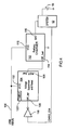
- FIG. 1 a block diagram of a mobile electronic device connected to a Universal Serial Bus (USB) host is shown.
- the mobile electronic device 10 comprises a central processing unit (CPU) 12 connected to a charger interface 14 which, in turn, is connected to a rechargeable battery 16.
- the CPU 12 is also connected to the rechargeable battery 16 and to a USB interface 18 which is connected to a USB port 20.
- the user connect the mobile electronic device 10 to the USB host 22 via a USB cable 24.
- the USB cable 24 is connected to a USB host port 26.
- a device interface 28, preferably a mobile electronic device interface, is connected to the USB host port 26 for transmitting data and current to and receiving data from the mobile electronic device 10.
- the USB host 22 further comprises a power source 30 and a CPU 32 which are both connected to the device interface 28.
- FIG. 2 a method of switching between a device suspend state and a device charging state for the Universal Serial Bus (USB) connected mobile electronic device is shown.
- USB Universal Serial Bus
- a check is performed to sense if inputs to the charger interface 14 are in a low state. When the inputs are in a low state, the indication is that there is no power being transferred to the CPU 12 and therefore no power for operating the device 10.
- the device may be turned off, the rechargeable battery 16 is dead or not present or the user may have placed the device in the device suspend mode.
- the status and level of a bus voltage (supplied by the power source 30 in the USB host) is sensed (step 34).
- the bus voltage is provided when the USB cable is connected between the USB host and the mobile electronic device. If the bus voltage is not sensed, a voltage supervisor continues to monitor for the presence of the bus voltage.
- the battery charger is then enabled (step 36).
- a timer is then enabled (step 38), and set to a pre-determined time period, preferably at least 100 msec. Once the timer is set, it begins to count down.
- a check is then performed to verify that the timer has not expired (step 40), i.e., that the predetermined time period has not elapsed. If the timer has expired, the battery charger is then disabled (step 42) and the device returns to the step of sensing the bus voltage (step 34). If the timer has not expired, a check is performed to determine if enumeration between the CPU and the USB host has been acknowledged (step 44).
- a check is performed to verify whether or not the CPU has transmitted a signal requesting the battery charger to remain enabled. If enumeration has not been acknowledged, verification that the timer has not elapsed is once again performed (step 40), and the battery is disabled (step 42) where the timer has elapsed.
- the CPU sets the device into the device charging state (step 46) and both powers the CPU and charges the battery using the bus voltage provided by the power source.
- the apparatus 50 comprises a battery charger 52 connected via its Vcc gate 54 to the VBUS power line from the USB host 22.
- a BAT gate 56 is connected to the CPU 12 along with the rechargeable battery 16.
- the CPU 12 is also connected to a CE_bar gate 58 of the battery charger 52.
- the mobile electronic device 10 When the battery is dead or not present, the mobile electronic device 10 is connected to the USB host 22 ( Figure 1 ), via the USB cable, to supply the VBUS voltage via the power line. It will be understood that the rechargeable battery is preferably decoupled from the mobile electronic device 10 in order to start the CPU 12 and that recoupling may occur at any time without affecting the operation of the device as long as power is provided by the VBUS power line.
- a system control signal 60 (seen as CHRG_EN_bar) from the CPU 12 is transmitted to the battery charger 52 to enable the charger when the VBUS is applied.
- This signal is typically a low state signal.
- the prior art apparatus does not wait for an enumeration acknowledgement and automatically enters the device charging state. In general, this goes against USB specifications. Therefore, when the rechargeable battery 16 is dead or not present and the CPU 12 has no power, the CHRG_EN_bar signal 60 is low and since the charger requires an active low state signal to enable the charging function, the battery charger 52 enables and provides power (in the form of current received from the VBUS power line) to the CPU 12.
- the USB host transmits a device suspend state request, the prior art circuit is unable to handle this request is the battery is dead or not present.
- the charger interface 14 comprises an input 100 from the VBUS power line which is connected to a Vcc gate 102 of a Voltage Supervisor and Reset module 104.
- the voltage supervisor and reset module 104 is a TPS3103 chip manufactured by Texas Instruments.
- the voltage supervisor and reset module 104 also comprises a MR_bar gate 106 and a RST_bar gate 108.
- the VBUS input 100 is also connected to a Vcc gate 110 of a battery charger 112.
- the RST_bar gate 108 is connected to a CE_bar gate 114 of the battery charger 112 while a BAT gate 116 of the battery charger 112 is connected to the rechargeable battery 16 via the CPU 12.
- the CPU 12 is also connected to the MR_bar gate 106 of the voltage supervisor and reset module 104 via a NOT gate (or inverter) 118. It will be understood that the signals being received at the MR_bar gate 106, the RST_bar gate 108, the CE_bar gate 114 and the NOT gate 118 are binary inputs so that the signal is either a low state (0) or a high state (1) signal.
- the USB cable 24 is connected to the USB port 20 of the mobile electronic device 10.
- the voltage supervisor and reset module 104 checks the status and level of the input 100 from the VBUS power line. The check is performed by the Vcc gate 102 of the voltage supervisor and reset module 104. After sensing the presence of the input 100, a timer 103 within the voltage supervisor and reset module 104 is started to determine when a predetermined time period, as described above, has elapsed.
- the timer 103 may be implemented in a number of ways, digitally or by analog means (with an RC circuit, for example).
- This predetermined time period is used to determine whether the mobile electronic device 10 has received an enumeration acknowledgement from the USB host 22 to draw power from the USB host via the VBUS input power line.
- a continuous check is performed by the voltage supervisor and reset module 104 to determine if the timer has expired.
- the CPU 12 is powered from the power source 30 in the USB host 22. This allows the charging process to begin before the enumeration is completed. Within the predetermined time period, the CPU 12 is required to enumerate with the USB host 22 to continue drawing current to power the device 10 and charge the battery.
- the voltage supervisor and reset module 104 After sensing the presence of the input 100, the voltage supervisor and reset module 104 transmits a low state (0) signal from its RST_bar gate 108 to the CE_bar gate 114 of the battery charger 112 to enable the battery charger 112.
- the battery charger 112 then transmits a voltage (current) to the CPU 12 and the rechargeable battery 16 using the current received in its Vcc gate 110 from the input 100.
- the CPU 12 requests enumeration from the USB CPU 32 in the USB host 22. Once it receives an enumeration acknowledgement, the CPU 12 transmits a high state CHRG_EN signal to the inverter 118 which inverts the signal to a low state signal before transmitting it to the MR_bar gate 106.
- the voltage supervisor and reset module 104 transmits a high signal from its RST_bar gate 108 to the CE_bar gate 114 to disable the battery charger 112.
- the initial low state signal transmitted from the voltage supervisor and reset module 104 to the battery charger is set for the predetermined time period and once the time period expires, the low state signal is switched to a high state signal which disables the battery charger.
- the voltage supervisor and reset module 104 transmits a low state signal to the CE_bar gate 114 and the battery charger 112 remains enabled so as to receive the input 100 and supply the necessary current for powering the mobile electronic device 10 and for charging the battery 16.
- the enablement of the battery charger 112 continues until the USB cable is disconnected from the USB port 20 or if a device suspend signal is transmitted along the data lines of the USB cable 24 from the USB CPU 32 to the CPU 12 of the mobile electronic device 10, indicating that the USB host 22 requests that the mobile electronic device 10 enter the device suspend state.
- the CPU 12 transmits a low state CHRG_EN signal to the inverter 118 which inverts the low state signal to a high state signal.
- the high state signal is then transmitted to the MR_bar gate 106 which causes the RST_bar gate 108 to transmit a high signal to the CE_bar gate 114 of the battery charger thus disabling the battery charger as requested by the USB host 22.
- the timer 103 counts down for a second predetermined time period, such as 150msec, so that if a subsequent low state signal is received by the MR_bar gate within the second time period, the high state signal is ignored. This allows the CPU 12 to reset without losing power to the battery charger 112. In general, when the CPU resets, all signals go to a low state. In this manner, a reset event does not cause the charger to be disabled since a reset event is not a device suspend state event.
- An advantage of the present invention is that if the CPU 12 fails to receive enumeration acknowledgement to enable the battery charger 112 prior to the predetermined time period timer elapsing, the battery charger is automatically disabled. Therefore, the mobile electronic device 10 does not continue to draw power from the power source 30 in the USB host 22. This provides an added function so that the CPU 12 of the mobile electronic device does not inadvertently draw current without proper enumeration.
- Another advantage of the present invention is that when the CPU 12 in the mobile electronic device 10 is instructed by the CPU 32 in the USB host 22 to enter the device suspend state, the CPU 12 disables the battery charger 112 by transmitting the low state signal to the inverter 118 and which is subsequently transmitted as a high state signal to the MR bar gate of the voltage supervisor and reset. If the timer 103 has expired, and there is no change of the input from the VBUS power line, the battery charger is disabled even though VBUS is still present as required by USB specifications.
- Another advantage of the present invention is that only one signal is required to switch the mobile electronic device from the device charging state to the device suspend state.
Landscapes
- Engineering & Computer Science (AREA)
- Theoretical Computer Science (AREA)
- General Engineering & Computer Science (AREA)
- Physics & Mathematics (AREA)
- General Physics & Mathematics (AREA)
- Power Engineering (AREA)
- Computer Hardware Design (AREA)
- Charge And Discharge Circuits For Batteries Or The Like (AREA)
- Secondary Cells (AREA)
- Power Sources (AREA)
Claims (11)
- Procédé de charge d'un dispositif électronique mobile (10) à partir d'un hôte (22) à bus série universel (USB pour "Universal Serial Bus") lors du raccordement du dispositif électronique mobile (10) à l'hôte (22) USB, comprenant :la détection que le Dispositif électronique mobile (10) est dans un état d'interruption de dispositif lorsqu'une interface (18) USB du dispositif (10) est raccordée à l'hôte (22) USB, dans lequel l'interface (18) USB comprend des circuits (112) de chargeur de batterie qui reçoivent une entrée d'énergie provenant de l'hôte (22) USB et engendrent une sortie d'énergie vers une source d'énergie rechargeable (16) et un dispositif de traitement (12) du dispositif (10) ; eten réponse à la détection que le dispositif électronique mobile (10) est dans l'état d'interruption de dispositif lorsqu'il est raccordé à l'hôte (22) USB :la détection d'une tension d'entrée en provenance de l'hôte (22) USB ;l'entrée dans un état de charge de dispositif en réponse à la détection de la tension d'entrée ;l'alimentation du dispositif de traitement (12) dans le dispositif électronique mobile (10) à partir de la tension d'entrée tandis que le dispositif électronique mobile (10) est dans l'état de charge de dispositif ;le fait de permettre au dispositif de traitement (12) de recevoir et de traiter des signaux de commande en provenance de l'hôte (22) USB ;une demande d'énumération en provenance de l'hôte (22) USB, etcaractérisé en ce que, si un accusé de réception d'énumération n'est pas reçu de l'hôte (22) USB à l'intérieur d'une période de temps prédéterminée, alors les circuits (14) de chargeur de batterie sont désactivés pour entrer dans l'état d'interruption, de dispositif.
- Procédé selon la revendication 1, dans lequel la période de temps prédéterminée est d'au moins 100 ms.
- Procédé selon l'une des revendications 1 et 2, comprenant en outre :la transmission d'un signal de validation dépendant du temps aux circuits (14) de chargeur de batterie en réponse à la détection de la tension d'entrée, le signal de validation dépendant du temps amenant le dispositif électronique mobile (10) à entrer dans l'état de charge de dispositif.
- Procédé selon la revendication 3, comprenant en outre :la réception d'un signal de commande d'état d'interruption de dispositif en provenance de l'hôte (22) USB ; eten réponse au signal de commande d'état d'interruption de dispositif, la désactivation des circuits (14) de chargeur de batterie pour entrer dans l'état d'interruption de dispositif.
- Dispositif électronique mobile (10), comprenant :une source d'énergie rechargeable (16) ;un dispositif de traitement (12) fonctionnant pour commander le fonctionnement du dispositif électronique mobile (10) ;une interface (18) de bus série universel (USB) destinée à raccorder la source d'énergie rechargeable (16) et le dispositif de traitement (12) à un hôte USB, dans lequel l'interface (18) USB comprend des circuits (112) de chargeur de batterie qui reçoivent une entrée d'énergie en provenance de l'hôte (22) USB et qui engendrent une sortie d'énergie vers la source d'énergie rechargeable (16) et le dispositif de traitement (12) ; etle dispositif de traitement (12) étant raccordé aux circuits (112) de chargeur de batterie, le dispositif de traitement (12) pouvant recevoir de l'énergie de la source d'énergie rechargeable (16) et de l'hôte (22) USB via les circuits (112) de chargeur de batterie,caractérisé :en ce que l'interface (18) USB fonctionne pour détecter que le dispositif électronique mobile (10) est dans un état d'interruption de dispositif lorsque l'interface (18) USB est raccordée à l'hôte (22) USB, et en réponse à la détection que le dispositif électronique mobile (10) est dans l'état d'interruption de dispositif lorsqu'il est raccordé à l'hôte (22) USB, détecter une entrée d'énergie en provenance de l'hôte (22) USB et alimenter le dispositif de traitement (12) à partir de l'hôte (22) USB via les circuits (112) de chargeur de batterie pendant une période de temps prédéterminée pendant qu'une demande d'énumération est transmise à l'hôte (22) USB ; eten ce que l'interface (18) USB peut en outre fonctionner pour désactiver les circuits (112) de chargeur de batterie si un accusé de réception d'énumération n'est pas reçu de l'hôte (22) USB à l'intérieur de la période de temps prédéterminée.
- Dispositif électronique mobile (10) selon la revendication 5, dans lequel l'interface (18) USB comprend :un module (104) superviseur de tension et de réinitialisation fonctionnant pour activer et désactiver la sortie d'énergie en provenance des circuits (112) de chargeur de batterie.
- Dispositif électronique mobile (10) selon la revendication 6, dans lequel le module (104) superviseur de tension et de réinitialisation peut en outre fonctionner pour recevoir un signal de commande d'état d'interruption de dispositif en provenance de l'hôte (22) USB amenant le module (104) superviseur de tension et de réinitialisation à désactiver les circuits (112) de chargeur de batterie.
- Dispositif électronique mobile (10) selon l'une des revendications 6 et 7, dans lequel le module (104) superviseur de tension et de réinitialisation peut fonctionner pour détecter l'entrée d'énergie en provenance de l'hôte (22) USB.
- Dispositif électronique mobile (10) selon l'une des revendications 6 à 8, dans lequel le module (104) superviseur de tension est de réinitialisation peut fonctionner pour activer un temporisateur en réponse à la détection de l'entrée d'énergie en provenance de l'hôte (22) USB, dans lequel le temporisateur peut fonctionner pour déterminer que la période de temps prédéterminée est écoulée.
- Dispositif électronique mobile (10) selon l'une des revendications 6 à 9, dans lequel le module (104) superviseur de tension et de réinitialisation peut fonctionner pour désactiver les circuits (112) de chargeur de batterie si le temporisateur expire avant que le module (104) superviseur de tension et de réinitialisation ne reçoive un signal en provenance du dispositif de traitement (12) indiquant qu'un accusé de réception d'énumération a été reçu de l'hôte (22) USB.
- Dispositif électronique mobile (10) selon l'une des revendications 5 à 10, dans lequel la période de temps prédéterminée est d'au moins 100 ms.
Applications Claiming Priority (2)
| Application Number | Priority Date | Filing Date | Title |
|---|---|---|---|
| GB0312079 | 2003-05-27 | ||
| GB0312079A GB2402271B (en) | 2003-05-27 | 2003-05-27 | Method and apparatus for handling a charging state in a mobile electronic device |
Publications (3)
| Publication Number | Publication Date |
|---|---|
| EP1482619A2 EP1482619A2 (fr) | 2004-12-01 |
| EP1482619A3 EP1482619A3 (fr) | 2005-07-27 |
| EP1482619B1 true EP1482619B1 (fr) | 2012-05-23 |
Family
ID=9958789
Family Applications (1)
| Application Number | Title | Priority Date | Filing Date |
|---|---|---|---|
| EP04012446A Expired - Lifetime EP1482619B1 (fr) | 2003-05-27 | 2004-05-26 | Procédé et dispositif de commande de l'état de charge dans un dispositif electronique mobile |
Country Status (11)
| Country | Link |
|---|---|
| US (5) | US7518343B2 (fr) |
| EP (1) | EP1482619B1 (fr) |
| JP (2) | JP3908753B2 (fr) |
| KR (1) | KR100811025B1 (fr) |
| CN (1) | CN100369349C (fr) |
| BR (1) | BRPI0402983B1 (fr) |
| CA (1) | CA2468388C (fr) |
| GB (1) | GB2402271B (fr) |
| HK (2) | HK1071234A1 (fr) |
| SG (1) | SG116561A1 (fr) |
| TW (1) | TWI256237B (fr) |
Families Citing this family (82)
| Publication number | Priority date | Publication date | Assignee | Title |
|---|---|---|---|---|
| GB2402271B (en) * | 2003-05-27 | 2006-04-19 | Research In Motion Ltd | Method and apparatus for handling a charging state in a mobile electronic device |
| EP1723493B1 (fr) * | 2004-02-17 | 2014-10-29 | BlackBerry Limited | Procede et appareil de gestion d'un etat de charge dans un dispositif electronique mobile |
| EP2562618A3 (fr) * | 2004-02-17 | 2013-05-22 | Research In Motion Limited | Procédé et appareil de gestion de l'état de charge dans un dispositif électronique mobile |
| US20050289257A1 (en) * | 2004-06-24 | 2005-12-29 | Fink Thomas M | Self-powered USB device with USB power line reset and related USB host and USB system |
| US7711039B2 (en) * | 2005-04-01 | 2010-05-04 | Freescale Semiconductor, Inc. | System and method for protecting low voltage transceiver |
| US20060244422A1 (en) * | 2005-04-27 | 2006-11-02 | Digiovanna Robert W | Methods and apparatus for charging a power source |
| KR101201121B1 (ko) * | 2005-12-02 | 2012-11-13 | 에스케이이노베이션 주식회사 | 전지 검사 장치 및 방법 |
| US7701173B2 (en) * | 2005-12-13 | 2010-04-20 | Research In Motion Limited | Charging and power supply for mobile devices |
| US7698490B2 (en) * | 2005-12-21 | 2010-04-13 | Nvidia Corporation | Passive USB power configuration switching |
| US7723951B2 (en) | 2006-06-30 | 2010-05-25 | Intel Corporation | Battery charging apparatus having a chute and method of recharging a battery |
| US7631111B2 (en) * | 2006-08-17 | 2009-12-08 | Standard Microsystems Corporation | System method for rapidly charging USB device's battery wherein USB device requests charging the battery at a higher power level |
| US7624202B2 (en) * | 2006-08-17 | 2009-11-24 | Standard Microsystems Corporation | System and method for enumerating a USB device using low power |
| JPWO2008044297A1 (ja) * | 2006-10-11 | 2010-02-04 | パナソニック株式会社 | 電子機器、および充電制御方法 |
| WO2008046077A2 (fr) * | 2006-10-13 | 2008-04-17 | Newton Peripherals Llc | Périphériques pour ordinateur portable |
| CN101573676B (zh) * | 2006-11-30 | 2012-10-03 | 诺基亚公司 | 串行总线外围设备的功率控制 |
| WO2008068552A1 (fr) * | 2006-12-08 | 2008-06-12 | Nokia Corporation | Connexions multiples sur une interface série unique |
| US8487583B2 (en) * | 2007-03-29 | 2013-07-16 | Nokia Corporation | Connection to a USB device dependent on detected battery criterion |
| KR20090028196A (ko) * | 2007-09-14 | 2009-03-18 | 삼성전자주식회사 | 휴대 단말기의 충전 장치 및 방법 |
| JP5057350B2 (ja) * | 2008-02-27 | 2012-10-24 | パナソニック株式会社 | 半導体集積回路、およびこれを備えた各種装置 |
| CN101546918B (zh) * | 2008-03-25 | 2012-05-30 | 鸿富锦精密工业(深圳)有限公司 | Usb充电装置及充电方法 |
| US8185759B1 (en) | 2008-11-06 | 2012-05-22 | Smsc Holdings S.A.R.L. | Methods and systems for interfacing bus powered devices with host devices providing limited power levels |
| US7882297B2 (en) * | 2009-02-20 | 2011-02-01 | Standard Microsystems Corporation | Serial bus hub with low power devices |
| CN101827162B (zh) * | 2009-03-04 | 2013-08-07 | 深圳富泰宏精密工业有限公司 | 手机usb接口侦测系统及方法 |
| CN101853966B (zh) * | 2009-03-31 | 2013-10-16 | 联芯科技有限公司 | 手持式终端的usb充电方法和装置 |
| TWI390818B (zh) * | 2009-07-14 | 2013-03-21 | Richpower Microelectronics | 改善充電器待機時之效率的裝置及方法,以及超低待機功率充電器 |
| TWI398759B (zh) | 2009-07-22 | 2013-06-11 | Htc Corp | 電源供應裝置、可判斷電源供應裝置的種類之可攜式電子裝置及其相關判斷方法 |
| CN101989751B (zh) * | 2009-07-30 | 2014-01-15 | 宏达国际电子股份有限公司 | 可携式电子装置及其相关判断方法 |
| CN101728859B (zh) * | 2009-12-17 | 2012-12-19 | 中兴通讯股份有限公司 | 移动终端间电池共享的系统、方法及移动终端 |
| JP5645438B2 (ja) * | 2010-03-25 | 2014-12-24 | キヤノン株式会社 | 給電装置及び給電方法 |
| US8826051B2 (en) * | 2010-07-26 | 2014-09-02 | Apple Inc. | Dynamic allocation of power budget to a system having non-volatile memory and a processor |
| CN103069404B (zh) * | 2010-08-24 | 2016-08-03 | 马维尔国际贸易有限公司 | 设备接口和装置 |
| WO2012030348A1 (fr) | 2010-09-02 | 2012-03-08 | Hewlett-Packard Development Company, L.P. | Port de charge |
| KR101717505B1 (ko) * | 2010-12-02 | 2017-03-17 | 삼성전자주식회사 | 외부 기기 충전 방법 및 이를 이용하는 디스플레이 장치 |
| US9436479B2 (en) * | 2011-01-17 | 2016-09-06 | Qualcomm Incorporated | Booting a mobile electronic device with a low battery based on a dynamic boot threshold |
| US8996771B1 (en) * | 2011-05-09 | 2015-03-31 | Google Inc. | System and method for communication via universal serial bus |
| US8332545B1 (en) | 2011-05-31 | 2012-12-11 | Smsc Holdings S.A.R.L. | USB switch which allows primary USB connection in response to USB signaling |
| CN102403754A (zh) * | 2011-06-30 | 2012-04-04 | 宣建民 | 一种具有续航能力的电源适配器 |
| US8788852B2 (en) * | 2011-07-01 | 2014-07-22 | Intel Corporation | System and method for providing power through a reverse local data transfer connection |
| US8816644B2 (en) | 2011-08-30 | 2014-08-26 | Perumala Corporation | Interrupting the charging status of a rechargeable battery |
| US8598850B2 (en) | 2011-08-30 | 2013-12-03 | Perumala Corporation | Devices and methods for optimizing rechargeable battery life |
| US8843770B2 (en) | 2011-10-31 | 2014-09-23 | Smsc Holdings S.A.R.L. | Device charging over USB using a plurality of handshakes |
| KR20130122266A (ko) * | 2012-04-30 | 2013-11-07 | 삼성전자주식회사 | 호스트모드에서 충전동작을 수행하는 시스템, 장치 및 방법 |
| US9092101B2 (en) | 2012-06-26 | 2015-07-28 | Google Technology Holdings LLC | Battery charging interrupt |
| US9395799B2 (en) | 2012-08-09 | 2016-07-19 | Nvidia Corporation | Power management techniques for USB interfaces |
| JP6288913B2 (ja) | 2012-12-28 | 2018-03-07 | キヤノン株式会社 | 電子機器及びプログラム |
| JP6164857B2 (ja) | 2013-02-12 | 2017-07-19 | キヤノン株式会社 | 給電装置、給電装置の制御方法、受電装置、受電装置の制御方法、プログラム |
| US11797469B2 (en) | 2013-05-07 | 2023-10-24 | Snap-On Incorporated | Method and system of using USB user interface in electronic torque wrench |
| CN104423278B (zh) | 2013-08-27 | 2017-09-26 | 华为终端有限公司 | 移动供电终端及其供电方法 |
| CN103491248B (zh) * | 2013-09-16 | 2016-01-20 | 华为技术有限公司 | 一种低电量开机的方法及用户设备 |
| USD757649S1 (en) | 2013-12-19 | 2016-05-31 | Perumala Corporation | Adapter |
| CN109308111B (zh) * | 2014-05-28 | 2022-03-01 | 精工爱普生株式会社 | 电子设备 |
| JP6277866B2 (ja) * | 2014-05-28 | 2018-02-14 | セイコーエプソン株式会社 | 充電装置及び電子機器 |
| US20160061173A1 (en) * | 2014-08-27 | 2016-03-03 | General Electric Company | System and method for determining health of an engine-generator set |
| CN107925691A (zh) | 2015-04-03 | 2018-04-17 | 品诺有限公司 | 个人无线媒体站 |
| JP2017045086A (ja) | 2015-08-24 | 2017-03-02 | キヤノン株式会社 | 電子機器及び制御方法 |
| JP6532357B2 (ja) * | 2015-08-31 | 2019-06-19 | キヤノン株式会社 | 送電装置、制御方法及びプログラム |
| CN105302278B (zh) * | 2015-10-19 | 2018-08-03 | 广东欧珀移动通信有限公司 | 指纹传感器串行外设接口的控制方法及装置和移动终端 |
| JP2017085853A (ja) * | 2015-10-30 | 2017-05-18 | キヤノン株式会社 | 電子機器及び電子機器の制御方法 |
| US10224732B2 (en) * | 2016-01-28 | 2019-03-05 | Dell Products L.P. | Information handling system external adapter and battery source |
| US10483773B2 (en) | 2016-01-28 | 2019-11-19 | Dell Products L.P. | Information handling system external adapter and battery source |
| CN105843365A (zh) * | 2016-03-24 | 2016-08-10 | 广东欧珀移动通信有限公司 | 一种传感器控制方法及装置 |
| DE102016107271A1 (de) * | 2016-04-20 | 2017-10-26 | Rwe International Se | Ladesystem und Verfahren zum Betreiben eines Ladesystems |
| CN106506821B (zh) * | 2016-10-24 | 2019-10-18 | Oppo广东移动通信有限公司 | 数据读取的方法及移动终端 |
| CN106877462B (zh) * | 2017-04-21 | 2019-04-12 | 维沃移动通信有限公司 | 一种检测充电状态的方法和充电器 |
| CN107193226B (zh) * | 2017-07-11 | 2020-07-17 | 广州飞傲电子科技有限公司 | 音乐播放器车载模式的控制方法及系统 |
| US10383482B1 (en) * | 2018-12-31 | 2019-08-20 | Miramore Inc. | Portable and rechargeable blender |
| US10702837B1 (en) | 2019-10-28 | 2020-07-07 | BlendJet, Inc. | Rechargeable blender with offset blades |
| US10828612B1 (en) | 2019-11-25 | 2020-11-10 | Blendjet Inc. | Locking and unlocking a blender |
| USD905496S1 (en) | 2019-11-25 | 2020-12-22 | Blendjet Inc. | Portable blender |
| USD948940S1 (en) | 2019-11-25 | 2022-04-19 | Blendjet Inc. | Base of a portable blender |
| USD953103S1 (en) | 2019-11-26 | 2022-05-31 | Blendjet Inc. | Portable blender lid |
| USD908428S1 (en) | 2019-12-02 | 2021-01-26 | Blendjet Inc. | Removable jar of a portable blender |
| USD911107S1 (en) | 2019-12-09 | 2021-02-23 | Blendjet Inc. | Button and light ring of a portable blender |
| US11531403B2 (en) | 2020-10-06 | 2022-12-20 | Blendjet Inc. | One button interface of a blender |
| USD1007947S1 (en) | 2020-11-20 | 2023-12-19 | Blendjet Inc. | Battery-powered portable blender |
| USD973437S1 (en) | 2020-11-20 | 2022-12-27 | Blendjet Inc. | Lid of a battery-powered portable blender |
| USD981179S1 (en) | 2020-11-20 | 2023-03-21 | Blendjet Inc. | Base of a battery-powered portable blender |
| USD1007948S1 (en) | 2020-11-25 | 2023-12-19 | Blendjet Inc. | Removable jar of a battery-powered portable blender |
| USD1014178S1 (en) | 2020-11-25 | 2024-02-13 | Blendjet Inc. | Battery-powered portable blender |
| US11690482B1 (en) | 2020-12-10 | 2023-07-04 | Blendjet Inc. | Power boost mode for a blender |
| US11824365B2 (en) | 2021-03-08 | 2023-11-21 | Blendjet Inc. | Portable blender with wireless charging |
| USD974841S1 (en) | 2021-03-08 | 2023-01-10 | Blendjet Inc. | Blade assembly for a portable blender |
Family Cites Families (63)
| Publication number | Priority date | Publication date | Assignee | Title |
|---|---|---|---|---|
| US3748386A (en) * | 1972-04-03 | 1973-07-24 | D Monney | Time-base error correction system |
| US4568096A (en) * | 1984-04-19 | 1986-02-04 | General Motors Corporation | Automatic vehicle level control |
| US5398265A (en) | 1988-11-10 | 1995-03-14 | Hughes Aircraft Company | Computer subsystem reset by address dependent RC discharge |
| US5028859A (en) | 1989-06-05 | 1991-07-02 | Motorola, Inc. | Multiple battery, multiple rate battery charger |
| US5250891A (en) * | 1991-05-13 | 1993-10-05 | Milwaukee Electric Tool Corporation | Battery charging method and apparatus |
| US5462439A (en) * | 1993-04-19 | 1995-10-31 | Keith; Arlie L. | Charging batteries of electric vehicles |
| JP2959657B2 (ja) * | 1993-05-13 | 1999-10-06 | キヤノン株式会社 | 電子機器 |
| US6101421A (en) | 1993-09-10 | 2000-08-08 | Motorola, Inc. | Reset recovery in a microprocessor controlled device |
| US5519346A (en) | 1994-06-22 | 1996-05-21 | Motorola, Inc. | Selective restart circuit for an electronic device |
| JP3733554B2 (ja) * | 1994-10-31 | 2006-01-11 | 富士通株式会社 | バッテリ駆動型電子機器 |
| JP2986059B2 (ja) * | 1995-03-08 | 1999-12-06 | インターナショナル・ビジネス・マシーンズ・コーポレイション | バッテリ充電装置 |
| US5712568A (en) * | 1995-09-05 | 1998-01-27 | Ford Motor Company | Battery voltage measurement system |
| US5898290A (en) * | 1995-09-07 | 1999-04-27 | Norand Corporation | Battery pack with capacity and pre-removal indicators |
| JP3439035B2 (ja) * | 1996-07-30 | 2003-08-25 | 三洋電機株式会社 | 電池の過放電を防止するパック電池 |
| GB9623612D0 (en) | 1996-11-13 | 1997-01-08 | Rca Thomson Licensing Corp | Separate power supplies for standby operation |
| KR100259263B1 (ko) * | 1997-05-21 | 2000-06-15 | 윤종용 | 휴대용 컴퓨터 시스템의 배터리 충전회로 및 그 충전방법 |
| KR100258043B1 (ko) * | 1997-10-27 | 2000-06-01 | 에릭 발리베 | 복합전기자동차용 보조동력장치의 제어시스템 |
| US5926006A (en) * | 1997-11-03 | 1999-07-20 | International Business Machines Corporation | Modular electronic apparatus with battery charging control |
| JP2000032684A (ja) * | 1998-07-08 | 2000-01-28 | Toyota Autom Loom Works Ltd | 充電回路および方法 |
| US6357011B2 (en) * | 1998-07-15 | 2002-03-12 | Gateway, Inc. | Bus-powered computer peripheral with supplement battery power to overcome bus-power limit |
| US6262563B1 (en) * | 1998-09-11 | 2001-07-17 | Keith S. Champlin | Method and apparatus for measuring complex admittance of cells and batteries |
| JP2000105638A (ja) | 1998-09-29 | 2000-04-11 | Nec Corp | Usbデバイス及びusb接続システム |
| US6191552B1 (en) * | 1999-01-25 | 2001-02-20 | Dell Usa, L.P. | External universal battery charging apparatus and method |
| SE516285C2 (sv) * | 1999-01-27 | 2001-12-10 | Ericsson Telefon Ab L M | Ett förfarande som möjliggör kommunikation mellan en elektronisk anordning och ett batteri, en apparat som innefattar en elektronisk anordning och ett batteri, samt ett batteri som möjliggör kommunikation |
| US6211649B1 (en) * | 1999-03-25 | 2001-04-03 | Sourcenext Corporation | USB cable and method for charging battery of external apparatus by using USB cable |
| US6031362A (en) * | 1999-05-13 | 2000-02-29 | Bradley; Larry D. | Method and apparatus for feedback control of switch mode power supply output to linear regulators |
| US6153855A (en) * | 1999-05-20 | 2000-11-28 | Illinois Tool Works Inc. | Control of weld and auxiliary power output of a generator type welding power supply |
| US6633932B1 (en) | 1999-09-14 | 2003-10-14 | Texas Instruments Incorporated | Method and apparatus for using a universal serial bus to provide power to a portable electronic device |
| DE19944053C2 (de) | 1999-09-14 | 2001-08-02 | Infineon Technologies Ag | Vorrichtung und Verfahren zur Stromversorgung von Rechner-Zusatzgeräten über das Bussystem des Rechners |
| US6665801B1 (en) | 2000-01-27 | 2003-12-16 | Symbol Technologies, Inc. | Method and apparatus for charging a self powered USB device at different charge rates according to the charge level of a rechargeable element on the device |
| GB2362769A (en) * | 2000-05-26 | 2001-11-28 | Nokia Mobile Phones Ltd | Battery charging circuit in which power is supplied via a communications port |
| US6362599B1 (en) * | 2000-09-21 | 2002-03-26 | Delphi Technologies, Inc. | Method and apparatus for sensing the status of a vehicle |
| TW479393B (en) * | 2000-09-27 | 2002-03-11 | Acer Peripherals Inc | Automatic USB charging apparatus and its operating method |
| US6646561B1 (en) * | 2000-10-06 | 2003-11-11 | Battery Alert Ltd. | Method and device for in-use detecting low cranking strength of a combustion engine battery during engine starting |
| US6883715B1 (en) * | 2000-10-11 | 2005-04-26 | Stmicroelectronics, Inc. | Multi-mode smart card, system and associated methods |
| EP1198049A1 (fr) * | 2000-10-12 | 2002-04-17 | Sony International (Europe) GmbH | Circuit de charge pour le chargement d'une unité mobile utilisant un interface BSU |
| AU2002258369A1 (en) | 2000-12-19 | 2002-09-19 | Smal Camera Technologies, Inc. | Compact digital camera system |
| CA2517333C (fr) * | 2001-03-01 | 2007-11-27 | Research In Motion Limited | Systeme et methode d'alimentation et de charge d'un dispositif de communication mobile |
| CA2374344C (fr) * | 2001-03-01 | 2006-02-21 | Research In Motion Limited | Systeme et methode de charge multifonction |
| US6507172B2 (en) * | 2001-03-19 | 2003-01-14 | Maxim Integrated Products, Inc. | Universal serial bus powered battery charger |
| US6531854B2 (en) | 2001-03-30 | 2003-03-11 | Champion Microelectronic Corp. | Power factor correction circuit arrangement |
| US6853259B2 (en) | 2001-08-15 | 2005-02-08 | Gallitzin Allegheny Llc | Ring oscillator dynamic adjustments for auto calibration |
| US6812971B2 (en) * | 2001-09-11 | 2004-11-02 | Olympus Optical Co., Ltd. | Electronic apparatus, stand and electronic apparatus stand system |
| TW529243B (en) * | 2001-10-22 | 2003-04-21 | Winbond Electronics Corp | Power initiation apparatus of peripheral device |
| US20030110403A1 (en) | 2001-12-10 | 2003-06-12 | Intel Corporation | System for shared power supply in computer peripheral devices |
| TW543994U (en) * | 2001-12-25 | 2003-07-21 | Sheng-Shing Liau | Easy carrying multi-function charger |
| JP3904489B2 (ja) | 2002-07-04 | 2007-04-11 | 富士通株式会社 | 充電制御回路、充電器、電源回路、及び情報処理装置、並びに電池パック |
| JP3654274B2 (ja) * | 2002-08-30 | 2005-06-02 | セイコーエプソン株式会社 | データ転送制御装置、電子機器及び電源切替方法 |
| US6650089B1 (en) * | 2002-10-16 | 2003-11-18 | Texas Instruments Incorporated | Control circuit for multiple battery systems with capacity gauge on end equipment |
| US6833686B2 (en) * | 2003-02-21 | 2004-12-21 | Research In Motion Limited | Circuit and method of operation for an adaptive charge rate power supply |
| US7791319B2 (en) * | 2003-02-21 | 2010-09-07 | Research In Motion Limited | Circuit and method of operation for an electrical power supply |
| GB2402271B (en) | 2003-05-27 | 2006-04-19 | Research In Motion Ltd | Method and apparatus for handling a charging state in a mobile electronic device |
| GB2402819B (en) * | 2003-06-11 | 2005-08-03 | Research In Motion Ltd | Universal serial bus charger for a mobile device |
| EP2562618A3 (fr) | 2004-02-17 | 2013-05-22 | Research In Motion Limited | Procédé et appareil de gestion de l'état de charge dans un dispositif électronique mobile |
| EP1723493B1 (fr) | 2004-02-17 | 2014-10-29 | BlackBerry Limited | Procede et appareil de gestion d'un etat de charge dans un dispositif electronique mobile |
| JP4155978B2 (ja) * | 2004-03-30 | 2008-09-24 | 三洋電機株式会社 | 電源装置 |
| US20060043933A1 (en) * | 2004-08-31 | 2006-03-02 | Latinis Gary R | Battery voltage monitor |
| US7696717B2 (en) * | 2005-08-08 | 2010-04-13 | Continental Automotive Systems Us, Inc. | Battery energy management system for measuring a minimum battery voltage |
| US7750501B2 (en) * | 2005-10-27 | 2010-07-06 | Continental Automotive Systems Us, Inc. | System and method of over voltage control for a power system |
| US7602143B2 (en) * | 2005-11-04 | 2009-10-13 | Peter David Capizzo | System for replenishing energy sources onboard different types of automotive vehicles |
| JP4944654B2 (ja) * | 2007-03-30 | 2012-06-06 | キヤノン株式会社 | 電源装置、および記録装置 |
| US20110050164A1 (en) * | 2008-05-07 | 2011-03-03 | Afshin Partovi | System and methods for inductive charging, and improvements and uses thereof |
| US20110066515A1 (en) * | 2009-09-16 | 2011-03-17 | Horvath Ronald F | Automated electric plug-in station for charging electric and hybrid vehicles |
-
2003
- 2003-05-27 GB GB0312079A patent/GB2402271B/en not_active Expired - Lifetime
-
2004
- 2004-05-25 US US10/852,781 patent/US7518343B2/en active Active
- 2004-05-25 SG SG200405773A patent/SG116561A1/en unknown
- 2004-05-26 EP EP04012446A patent/EP1482619B1/fr not_active Expired - Lifetime
- 2004-05-27 TW TW093115115A patent/TWI256237B/zh not_active IP Right Cessation
- 2004-05-27 JP JP2004158375A patent/JP3908753B2/ja not_active Expired - Fee Related
- 2004-05-27 KR KR1020040037705A patent/KR100811025B1/ko active IP Right Grant
- 2004-05-27 CA CA002468388A patent/CA2468388C/fr not_active Expired - Lifetime
- 2004-05-27 BR BRPI0402983-6A patent/BRPI0402983B1/pt not_active IP Right Cessation
- 2004-05-27 CN CNB200410048812XA patent/CN100369349C/zh not_active Expired - Lifetime
-
2005
- 2005-02-12 HK HK05101126.0A patent/HK1071234A1/xx not_active IP Right Cessation
- 2005-05-31 HK HK05104576A patent/HK1073508A1/xx not_active IP Right Cessation
-
2006
- 2006-08-22 JP JP2006225446A patent/JP4144891B2/ja not_active Expired - Fee Related
-
2009
- 2009-04-07 US US12/419,897 patent/US7768239B2/en not_active Expired - Lifetime
-
2010
- 2010-07-23 US US12/842,763 patent/US7893660B2/en not_active Expired - Lifetime
-
2011
- 2011-02-21 US US13/031,493 patent/US8283897B2/en not_active Expired - Lifetime
-
2012
- 2012-10-04 US US13/645,152 patent/US8610407B2/en not_active Expired - Lifetime
Also Published As
| Publication number | Publication date |
|---|---|
| CN100369349C (zh) | 2008-02-13 |
| US8283897B2 (en) | 2012-10-09 |
| EP1482619A3 (fr) | 2005-07-27 |
| KR100811025B1 (ko) | 2008-03-11 |
| GB0312079D0 (en) | 2003-07-02 |
| HK1071234A1 (en) | 2005-07-08 |
| JP4144891B2 (ja) | 2008-09-03 |
| SG116561A1 (en) | 2005-11-28 |
| US8610407B2 (en) | 2013-12-17 |
| GB2402271B (en) | 2006-04-19 |
| CA2468388A1 (fr) | 2004-11-27 |
| US20100289456A1 (en) | 2010-11-18 |
| GB2402271A (en) | 2004-12-01 |
| US20130033226A1 (en) | 2013-02-07 |
| US20090200989A1 (en) | 2009-08-13 |
| US7893660B2 (en) | 2011-02-22 |
| JP2004357497A (ja) | 2004-12-16 |
| EP1482619A2 (fr) | 2004-12-01 |
| TWI256237B (en) | 2006-06-01 |
| BRPI0402983B1 (pt) | 2021-07-27 |
| JP2007020398A (ja) | 2007-01-25 |
| US20110140674A1 (en) | 2011-06-16 |
| KR20040102341A (ko) | 2004-12-04 |
| TW200511813A (en) | 2005-03-16 |
| BRPI0402983A (pt) | 2005-01-25 |
| CN1574539A (zh) | 2005-02-02 |
| US7768239B2 (en) | 2010-08-03 |
| JP3908753B2 (ja) | 2007-04-25 |
| HK1073508A1 (en) | 2005-10-07 |
| CA2468388C (fr) | 2009-09-01 |
| US7518343B2 (en) | 2009-04-14 |
| US20040239294A1 (en) | 2004-12-02 |
Similar Documents
| Publication | Publication Date | Title |
|---|---|---|
| EP1482619B1 (fr) | Procédé et dispositif de commande de l'état de charge dans un dispositif electronique mobile | |
| US8111040B2 (en) | Method and apparatus for handling a charging state in a mobile electronic device | |
| CA2556446C (fr) | Procede et appareil de gestion de l'etat de charge dans un dispositif electronique mobile | |
| EP2130108B1 (fr) | Connexion à un dispositif usb | |
| US20040042138A1 (en) | Data transfer control device, electronic equipment, and power supply switching method | |
| US20100060233A1 (en) | Charger with USB detection | |
| WO2013152662A1 (fr) | Procédé d'alimentation pour dispositif terminal, et dispositif terminal correspondant | |
| EP1869782B1 (fr) | Système et procédé de protection d'un émetteur-récepteur basse tension |
Legal Events
| Date | Code | Title | Description |
|---|---|---|---|
| PUAI | Public reference made under article 153(3) epc to a published international application that has entered the european phase |
Free format text: ORIGINAL CODE: 0009012 |
|
| 17P | Request for examination filed |
Effective date: 20040526 |
|
| AK | Designated contracting states |
Kind code of ref document: A2 Designated state(s): AT BE BG CH CY CZ DE DK EE ES FI FR GB GR HU IE IT LI LU MC NL PL PT RO SE SI SK TR |
|
| AX | Request for extension of the european patent |
Extension state: AL HR LT LV MK |
|
| PUAL | Search report despatched |
Free format text: ORIGINAL CODE: 0009013 |
|
| RIC1 | Information provided on ipc code assigned before grant |
Ipc: 7H 02J 7/00 A Ipc: 7G 06F 1/26 B |
|
| REG | Reference to a national code |
Ref country code: HK Ref legal event code: DE Ref document number: 1071234 Country of ref document: HK |
|
| AK | Designated contracting states |
Kind code of ref document: A3 Designated state(s): AT BE BG CH CY CZ DE DK EE ES FI FR GB GR HU IE IT LI LU MC NL PL PT RO SE SI SK TR |
|
| AX | Request for extension of the european patent |
Extension state: AL HR LT LV MK |
|
| AKX | Designation fees paid |
Designated state(s): AT BE BG CH CY CZ DE DK EE ES FI FR GB GR HU IE IT LI LU MC NL PL PT RO SE SI SK TR |
|
| AXX | Extension fees paid |
Extension state: HR Payment date: 20060104 Extension state: AL Payment date: 20060104 Extension state: LT Payment date: 20060104 Extension state: MK Payment date: 20060104 Extension state: LV Payment date: 20060104 |
|
| REG | Reference to a national code |
Ref country code: DE Ref legal event code: R079 Ref document number: 602004037870 Country of ref document: DE Free format text: PREVIOUS MAIN CLASS: H02J0007000000 Ipc: G06F0001320000 |
|
| GRAP | Despatch of communication of intention to grant a patent |
Free format text: ORIGINAL CODE: EPIDOSNIGR1 |
|
| RIC1 | Information provided on ipc code assigned before grant |
Ipc: H02J 7/00 20060101ALI20111117BHEP Ipc: G06F 1/32 20060101AFI20111117BHEP Ipc: G06F 1/26 20060101ALI20111117BHEP |
|
| GRAS | Grant fee paid |
Free format text: ORIGINAL CODE: EPIDOSNIGR3 |
|
| GRAA | (expected) grant |
Free format text: ORIGINAL CODE: 0009210 |
|
| AK | Designated contracting states |
Kind code of ref document: B1 Designated state(s): AT BE BG CH CY CZ DE DK EE ES FI FR GB GR HU IE IT LI LU MC NL PL PT RO SE SI SK TR |
|
| AX | Request for extension of the european patent |
Extension state: AL HR LT LV MK |
|
| REG | Reference to a national code |
Ref country code: GB Ref legal event code: FG4D |
|
| REG | Reference to a national code |
Ref country code: CH Ref legal event code: EP |
|
| REG | Reference to a national code |
Ref country code: AT Ref legal event code: REF Ref document number: 559354 Country of ref document: AT Kind code of ref document: T Effective date: 20120615 |
|
| REG | Reference to a national code |
Ref country code: IE Ref legal event code: FG4D |
|
| REG | Reference to a national code |
Ref country code: DE Ref legal event code: R096 Ref document number: 602004037870 Country of ref document: DE Effective date: 20120719 |
|
| REG | Reference to a national code |
Ref country code: NL Ref legal event code: T3 |
|
| REG | Reference to a national code |
Ref country code: LT Ref legal event code: MG9D Effective date: 20120523 |
|
| PG25 | Lapsed in a contracting state [announced via postgrant information from national office to epo] |
Ref country code: FI Free format text: LAPSE BECAUSE OF FAILURE TO SUBMIT A TRANSLATION OF THE DESCRIPTION OR TO PAY THE FEE WITHIN THE PRESCRIBED TIME-LIMIT Effective date: 20120523 Ref country code: CY Free format text: LAPSE BECAUSE OF FAILURE TO SUBMIT A TRANSLATION OF THE DESCRIPTION OR TO PAY THE FEE WITHIN THE PRESCRIBED TIME-LIMIT Effective date: 20120523 Ref country code: SE Free format text: LAPSE BECAUSE OF FAILURE TO SUBMIT A TRANSLATION OF THE DESCRIPTION OR TO PAY THE FEE WITHIN THE PRESCRIBED TIME-LIMIT Effective date: 20120523 |
|
| REG | Reference to a national code |
Ref country code: AT Ref legal event code: MK05 Ref document number: 559354 Country of ref document: AT Kind code of ref document: T Effective date: 20120523 |
|
| PG25 | Lapsed in a contracting state [announced via postgrant information from national office to epo] |
Ref country code: GR Free format text: LAPSE BECAUSE OF FAILURE TO SUBMIT A TRANSLATION OF THE DESCRIPTION OR TO PAY THE FEE WITHIN THE PRESCRIBED TIME-LIMIT Effective date: 20120824 Ref country code: SI Free format text: LAPSE BECAUSE OF FAILURE TO SUBMIT A TRANSLATION OF THE DESCRIPTION OR TO PAY THE FEE WITHIN THE PRESCRIBED TIME-LIMIT Effective date: 20120523 Ref country code: PT Free format text: LAPSE BECAUSE OF FAILURE TO SUBMIT A TRANSLATION OF THE DESCRIPTION OR TO PAY THE FEE WITHIN THE PRESCRIBED TIME-LIMIT Effective date: 20120924 |
|
| PG25 | Lapsed in a contracting state [announced via postgrant information from national office to epo] |
Ref country code: BE Free format text: LAPSE BECAUSE OF FAILURE TO SUBMIT A TRANSLATION OF THE DESCRIPTION OR TO PAY THE FEE WITHIN THE PRESCRIBED TIME-LIMIT Effective date: 20120523 Ref country code: MC Free format text: LAPSE BECAUSE OF NON-PAYMENT OF DUE FEES Effective date: 20120531 |
|
| REG | Reference to a national code |
Ref country code: CH Ref legal event code: PL |
|
| REG | Reference to a national code |
Ref country code: HK Ref legal event code: GR Ref document number: 1071234 Country of ref document: HK |
|
| PG25 | Lapsed in a contracting state [announced via postgrant information from national office to epo] |
Ref country code: SK Free format text: LAPSE BECAUSE OF FAILURE TO SUBMIT A TRANSLATION OF THE DESCRIPTION OR TO PAY THE FEE WITHIN THE PRESCRIBED TIME-LIMIT Effective date: 20120523 Ref country code: LI Free format text: LAPSE BECAUSE OF NON-PAYMENT OF DUE FEES Effective date: 20120531 Ref country code: CZ Free format text: LAPSE BECAUSE OF FAILURE TO SUBMIT A TRANSLATION OF THE DESCRIPTION OR TO PAY THE FEE WITHIN THE PRESCRIBED TIME-LIMIT Effective date: 20120523 Ref country code: CH Free format text: LAPSE BECAUSE OF NON-PAYMENT OF DUE FEES Effective date: 20120531 Ref country code: EE Free format text: LAPSE BECAUSE OF FAILURE TO SUBMIT A TRANSLATION OF THE DESCRIPTION OR TO PAY THE FEE WITHIN THE PRESCRIBED TIME-LIMIT Effective date: 20120523 Ref country code: AT Free format text: LAPSE BECAUSE OF FAILURE TO SUBMIT A TRANSLATION OF THE DESCRIPTION OR TO PAY THE FEE WITHIN THE PRESCRIBED TIME-LIMIT Effective date: 20120523 Ref country code: DK Free format text: LAPSE BECAUSE OF FAILURE TO SUBMIT A TRANSLATION OF THE DESCRIPTION OR TO PAY THE FEE WITHIN THE PRESCRIBED TIME-LIMIT Effective date: 20120523 Ref country code: RO Free format text: LAPSE BECAUSE OF FAILURE TO SUBMIT A TRANSLATION OF THE DESCRIPTION OR TO PAY THE FEE WITHIN THE PRESCRIBED TIME-LIMIT Effective date: 20120523 |
|
| REG | Reference to a national code |
Ref country code: IE Ref legal event code: MM4A |
|
| PG25 | Lapsed in a contracting state [announced via postgrant information from national office to epo] |
Ref country code: IT Free format text: LAPSE BECAUSE OF FAILURE TO SUBMIT A TRANSLATION OF THE DESCRIPTION OR TO PAY THE FEE WITHIN THE PRESCRIBED TIME-LIMIT Effective date: 20120523 Ref country code: PL Free format text: LAPSE BECAUSE OF FAILURE TO SUBMIT A TRANSLATION OF THE DESCRIPTION OR TO PAY THE FEE WITHIN THE PRESCRIBED TIME-LIMIT Effective date: 20120523 |
|
| PLBE | No opposition filed within time limit |
Free format text: ORIGINAL CODE: 0009261 |
|
| STAA | Information on the status of an ep patent application or granted ep patent |
Free format text: STATUS: NO OPPOSITION FILED WITHIN TIME LIMIT |
|
| PG25 | Lapsed in a contracting state [announced via postgrant information from national office to epo] |
Ref country code: ES Free format text: LAPSE BECAUSE OF FAILURE TO SUBMIT A TRANSLATION OF THE DESCRIPTION OR TO PAY THE FEE WITHIN THE PRESCRIBED TIME-LIMIT Effective date: 20120903 Ref country code: IE Free format text: LAPSE BECAUSE OF NON-PAYMENT OF DUE FEES Effective date: 20120526 |
|
| 26N | No opposition filed |
Effective date: 20130226 |
|
| REG | Reference to a national code |
Ref country code: DE Ref legal event code: R097 Ref document number: 602004037870 Country of ref document: DE Effective date: 20130226 |
|
| PG25 | Lapsed in a contracting state [announced via postgrant information from national office to epo] |
Ref country code: BG Free format text: LAPSE BECAUSE OF FAILURE TO SUBMIT A TRANSLATION OF THE DESCRIPTION OR TO PAY THE FEE WITHIN THE PRESCRIBED TIME-LIMIT Effective date: 20120823 |
|
| PG25 | Lapsed in a contracting state [announced via postgrant information from national office to epo] |
Ref country code: TR Free format text: LAPSE BECAUSE OF FAILURE TO SUBMIT A TRANSLATION OF THE DESCRIPTION OR TO PAY THE FEE WITHIN THE PRESCRIBED TIME-LIMIT Effective date: 20120523 |
|
| PG25 | Lapsed in a contracting state [announced via postgrant information from national office to epo] |
Ref country code: LU Free format text: LAPSE BECAUSE OF NON-PAYMENT OF DUE FEES Effective date: 20120526 |
|
| PG25 | Lapsed in a contracting state [announced via postgrant information from national office to epo] |
Ref country code: HU Free format text: LAPSE BECAUSE OF FAILURE TO SUBMIT A TRANSLATION OF THE DESCRIPTION OR TO PAY THE FEE WITHIN THE PRESCRIBED TIME-LIMIT Effective date: 20040526 |
|
| REG | Reference to a national code |
Ref country code: DE Ref legal event code: R082 Ref document number: 602004037870 Country of ref document: DE Representative=s name: MERH-IP MATIAS ERNY REICHL HOFFMANN, DE |
|
| REG | Reference to a national code |
Ref country code: DE Ref legal event code: R081 Ref document number: 602004037870 Country of ref document: DE Owner name: BLACKBERRY LIMITED, WATERLOO, CA Free format text: FORMER OWNER: RESEARCH IN MOTION LIMITED, WATERLOO, ONTARIO, CA Effective date: 20140925 Ref country code: DE Ref legal event code: R081 Ref document number: 602004037870 Country of ref document: DE Owner name: BLACKBERRY LIMITED, WATERLOO, CA Free format text: FORMER OWNER: RESEARCH IN MOTION LTD., WATERLOO, ONTARIO, CA Effective date: 20120525 Ref country code: DE Ref legal event code: R082 Ref document number: 602004037870 Country of ref document: DE Representative=s name: MERH-IP MATIAS ERNY REICHL HOFFMANN, DE Effective date: 20140925 Ref country code: DE Ref legal event code: R082 Ref document number: 602004037870 Country of ref document: DE Representative=s name: MERH-IP MATIAS ERNY REICHL HOFFMANN PATENTANWA, DE Effective date: 20140925 Ref country code: DE Ref legal event code: R081 Ref document number: 602004037870 Country of ref document: DE Owner name: FUNDAMENTAL INNOVATION SYSTEMS INTERNATIONAL L, US Free format text: FORMER OWNER: RESEARCH IN MOTION LTD., WATERLOO, ONTARIO, CA Effective date: 20120525 Ref country code: DE Ref legal event code: R081 Ref document number: 602004037870 Country of ref document: DE Owner name: FUNDAMENTAL INNOVATION SYSTEMS INTERNATIONAL L, US Free format text: FORMER OWNER: RESEARCH IN MOTION LIMITED, WATERLOO, ONTARIO, CA Effective date: 20140925 Ref country code: DE Ref legal event code: R082 Ref document number: 602004037870 Country of ref document: DE Representative=s name: VOSSIUS & PARTNER PATENTANWAELTE RECHTSANWAELT, DE Effective date: 20140925 |
|
| REG | Reference to a national code |
Ref country code: FR Ref legal event code: PLFP Year of fee payment: 12 |
|
| REG | Reference to a national code |
Ref country code: NL Ref legal event code: TD Effective date: 20150831 |
|
| REG | Reference to a national code |
Ref country code: FR Ref legal event code: CD Owner name: BLACKBERRY LIMITED, CA Effective date: 20151117 Ref country code: FR Ref legal event code: CA Effective date: 20151117 |
|
| REG | Reference to a national code |
Ref country code: FR Ref legal event code: PLFP Year of fee payment: 13 |
|
| REG | Reference to a national code |
Ref country code: FR Ref legal event code: PLFP Year of fee payment: 14 |
|
| REG | Reference to a national code |
Ref country code: DE Ref legal event code: R082 Ref document number: 602004037870 Country of ref document: DE Representative=s name: MERH-IP MATIAS ERNY REICHL HOFFMANN PATENTANWA, DE Ref country code: DE Ref legal event code: R081 Ref document number: 602004037870 Country of ref document: DE Owner name: FUNDAMENTAL INNOVATION SYSTEMS INTERNATIONAL L, US Free format text: FORMER OWNER: BLACKBERRY LIMITED, WATERLOO, ONTARIO, CA Ref country code: DE Ref legal event code: R082 Ref document number: 602004037870 Country of ref document: DE Representative=s name: VOSSIUS & PARTNER PATENTANWAELTE RECHTSANWAELT, DE |
|
| REG | Reference to a national code |
Ref country code: DE Ref legal event code: R082 Ref document number: 602004037870 Country of ref document: DE Representative=s name: MERH-IP MATIAS ERNY REICHL HOFFMANN PATENTANWA, DE Ref country code: DE Ref legal event code: R081 Ref document number: 602004037870 Country of ref document: DE Owner name: FUNDAMENTAL INNOVATION SYSTEMS INTERNATIONAL L, US Free format text: FORMER OWNER: FUNDAMENTAL INNOVATION SYSTEMS INTERNATIONAL LLC, SOUTHLAKE, TEX., US Ref country code: DE Ref legal event code: R082 Ref document number: 602004037870 Country of ref document: DE Representative=s name: VOSSIUS & PARTNER PATENTANWAELTE RECHTSANWAELT, DE |
|
| REG | Reference to a national code |
Ref country code: FR Ref legal event code: TP Owner name: FUNDAMENTAL INNOVATION SYSTEMS INTERNATIONAL L, US Effective date: 20171127 |
|
| REG | Reference to a national code |
Ref country code: DE Ref legal event code: R082 Ref document number: 602004037870 Country of ref document: DE Representative=s name: VOSSIUS & PARTNER PATENTANWAELTE RECHTSANWAELT, DE |
|
| REG | Reference to a national code |
Ref country code: GB Ref legal event code: 732E Free format text: REGISTERED BETWEEN 20180125 AND 20180131 |
|
| REG | Reference to a national code |
Ref country code: FR Ref legal event code: PLFP Year of fee payment: 15 |
|
| PGFP | Annual fee paid to national office [announced via postgrant information from national office to epo] |
Ref country code: NL Payment date: 20200526 Year of fee payment: 17 Ref country code: FR Payment date: 20200525 Year of fee payment: 17 |
|
| REG | Reference to a national code |
Ref country code: NL Ref legal event code: MM Effective date: 20210601 |
|
| PG25 | Lapsed in a contracting state [announced via postgrant information from national office to epo] |
Ref country code: NL Free format text: LAPSE BECAUSE OF NON-PAYMENT OF DUE FEES Effective date: 20210601 Ref country code: FR Free format text: LAPSE BECAUSE OF NON-PAYMENT OF DUE FEES Effective date: 20210531 |
|
| PGFP | Annual fee paid to national office [announced via postgrant information from national office to epo] |
Ref country code: GB Payment date: 20220527 Year of fee payment: 19 Ref country code: DE Payment date: 20220527 Year of fee payment: 19 |
|
| REG | Reference to a national code |
Ref country code: DE Ref legal event code: R119 Ref document number: 602004037870 Country of ref document: DE |
|
| GBPC | Gb: european patent ceased through non-payment of renewal fee |
Effective date: 20230526 |
|
| PG25 | Lapsed in a contracting state [announced via postgrant information from national office to epo] |
Ref country code: DE Free format text: LAPSE BECAUSE OF NON-PAYMENT OF DUE FEES Effective date: 20231201 Ref country code: GB Free format text: LAPSE BECAUSE OF NON-PAYMENT OF DUE FEES Effective date: 20230526 |