EP1482340A2 - Module optique capable de faciliter l'état de déverrouillage avec une cage qui contient le module optique. - Google Patents
Module optique capable de faciliter l'état de déverrouillage avec une cage qui contient le module optique. Download PDFInfo
- Publication number
- EP1482340A2 EP1482340A2 EP20040090212 EP04090212A EP1482340A2 EP 1482340 A2 EP1482340 A2 EP 1482340A2 EP 20040090212 EP20040090212 EP 20040090212 EP 04090212 A EP04090212 A EP 04090212A EP 1482340 A2 EP1482340 A2 EP 1482340A2
- Authority
- EP
- European Patent Office
- Prior art keywords
- case
- cage
- locking member
- connector
- optical module
- Prior art date
- Legal status (The legal status is an assumption and is not a legal conclusion. Google has not performed a legal analysis and makes no representation as to the accuracy of the status listed.)
- Withdrawn
Links
- 230000003287 optical effect Effects 0.000 title claims abstract description 189
- 239000013307 optical fiber Substances 0.000 claims abstract description 19
- 238000004891 communication Methods 0.000 claims description 26
- 230000014759 maintenance of location Effects 0.000 claims description 18
- 230000000717 retained effect Effects 0.000 claims description 16
- 238000000034 method Methods 0.000 claims description 13
- 239000000428 dust Substances 0.000 claims description 11
- 239000000463 material Substances 0.000 claims description 9
- 239000011347 resin Substances 0.000 claims description 5
- 229920005989 resin Polymers 0.000 claims description 5
- 239000007769 metal material Substances 0.000 claims description 3
- 238000003825 pressing Methods 0.000 claims description 2
- 238000010586 diagram Methods 0.000 description 11
- 230000007246 mechanism Effects 0.000 description 6
- 229910052751 metal Inorganic materials 0.000 description 4
- 239000002184 metal Substances 0.000 description 4
- 238000000465 moulding Methods 0.000 description 4
- 238000012856 packing Methods 0.000 description 4
- 239000000758 substrate Substances 0.000 description 4
- 239000004734 Polyphenylene sulfide Substances 0.000 description 3
- 238000009826 distribution Methods 0.000 description 3
- 230000008030 elimination Effects 0.000 description 3
- 238000003379 elimination reaction Methods 0.000 description 3
- 229920000069 polyphenylene sulfide Polymers 0.000 description 3
- 239000000853 adhesive Substances 0.000 description 2
- 230000001070 adhesive effect Effects 0.000 description 2
- 238000005452 bending Methods 0.000 description 2
- 230000005540 biological transmission Effects 0.000 description 2
- -1 for example Substances 0.000 description 2
- 229910001220 stainless steel Inorganic materials 0.000 description 2
- 239000010935 stainless steel Substances 0.000 description 2
- 229920000265 Polyparaphenylene Polymers 0.000 description 1
- UCKMPCXJQFINFW-UHFFFAOYSA-N Sulphide Chemical compound [S-2] UCKMPCXJQFINFW-UHFFFAOYSA-N 0.000 description 1
- HCHKCACWOHOZIP-UHFFFAOYSA-N Zinc Chemical compound [Zn] HCHKCACWOHOZIP-UHFFFAOYSA-N 0.000 description 1
- 230000004308 accommodation Effects 0.000 description 1
- 230000009471 action Effects 0.000 description 1
- 229910052782 aluminium Inorganic materials 0.000 description 1
- XAGFODPZIPBFFR-UHFFFAOYSA-N aluminium Chemical compound [Al] XAGFODPZIPBFFR-UHFFFAOYSA-N 0.000 description 1
- 238000006243 chemical reaction Methods 0.000 description 1
- 230000006835 compression Effects 0.000 description 1
- 238000007906 compression Methods 0.000 description 1
- 230000002401 inhibitory effect Effects 0.000 description 1
- 238000003780 insertion Methods 0.000 description 1
- 230000037431 insertion Effects 0.000 description 1
- 238000009434 installation Methods 0.000 description 1
- 238000004519 manufacturing process Methods 0.000 description 1
- 230000004048 modification Effects 0.000 description 1
- 238000012986 modification Methods 0.000 description 1
- 230000008520 organization Effects 0.000 description 1
- 230000008569 process Effects 0.000 description 1
- 230000002940 repellent Effects 0.000 description 1
- 239000005871 repellent Substances 0.000 description 1
- 230000004044 response Effects 0.000 description 1
- 229910052725 zinc Inorganic materials 0.000 description 1
- 239000011701 zinc Substances 0.000 description 1
Images


Classifications
-
- H—ELECTRICITY
- H01—ELECTRIC ELEMENTS
- H01R—ELECTRICALLY-CONDUCTIVE CONNECTIONS; STRUCTURAL ASSOCIATIONS OF A PLURALITY OF MUTUALLY-INSULATED ELECTRICAL CONNECTING ELEMENTS; COUPLING DEVICES; CURRENT COLLECTORS
- H01R13/00—Details of coupling devices of the kinds covered by groups H01R12/70 or H01R24/00 - H01R33/00
- H01R13/62—Means for facilitating engagement or disengagement of coupling parts or for holding them in engagement
- H01R13/629—Additional means for facilitating engagement or disengagement of coupling parts, e.g. aligning or guiding means, levers, gas pressure electrical locking indicators, manufacturing tolerances
-
- G—PHYSICS
- G02—OPTICS
- G02B—OPTICAL ELEMENTS, SYSTEMS OR APPARATUS
- G02B6/00—Light guides; Structural details of arrangements comprising light guides and other optical elements, e.g. couplings
- G02B6/24—Coupling light guides
- G02B6/36—Mechanical coupling means
- G02B6/38—Mechanical coupling means having fibre to fibre mating means
- G02B6/3807—Dismountable connectors, i.e. comprising plugs
- G02B6/3897—Connectors fixed to housings, casing, frames or circuit boards
-
- G—PHYSICS
- G02—OPTICS
- G02B—OPTICAL ELEMENTS, SYSTEMS OR APPARATUS
- G02B6/00—Light guides; Structural details of arrangements comprising light guides and other optical elements, e.g. couplings
- G02B6/24—Coupling light guides
- G02B6/36—Mechanical coupling means
- G02B6/38—Mechanical coupling means having fibre to fibre mating means
- G02B6/3807—Dismountable connectors, i.e. comprising plugs
- G02B6/389—Dismountable connectors, i.e. comprising plugs characterised by the method of fastening connecting plugs and sockets, e.g. screw- or nut-lock, snap-in, bayonet type
- G02B6/3893—Push-pull type, e.g. snap-in, push-on
-
- G—PHYSICS
- G02—OPTICS
- G02B—OPTICAL ELEMENTS, SYSTEMS OR APPARATUS
- G02B6/00—Light guides; Structural details of arrangements comprising light guides and other optical elements, e.g. couplings
- G02B6/24—Coupling light guides
- G02B6/42—Coupling light guides with opto-electronic elements
- G02B6/4292—Coupling light guides with opto-electronic elements the light guide being disconnectable from the opto-electronic element, e.g. mutually self aligning arrangements
Definitions
- the invention relates to an optical module for use in optical communication . More particularly, it relates to an optical module which can be locked in a cage for accommodating the case of the optical module.
- optical transceiver which comprises a light emitting element and a light receiving element for performing opto-electric conversion to perform communication through optical fibers.
- optical transceivers comprises an optical unit, including a light emitting element and a light receiving element, contained in a case, and is structured for removable accommodation in a cage mounted on a substrate.
- the cage has a socket mounted on the substrate, such that the optical transceiver plugged into the cage causes its connection terminals to come into connection with the socket.
- the optical transceiver thus constructed converts an optical signal communicated to/from an optical fiber to an electric signal communicated to/from the substrate, and vice versa to enable optical communication .
- an optical transceiver is withdrawn from the cage during operation of the optical transceiver, a communication device including the optical transceiver can fail, needless to say that a communication is interrupted in the middle. To prevent such trouble, the optical transceiver must be securely fixed within the cage at least during its operation.
- MSA MultiSource Agreement
- SFP Small Form-factor Pluggable
- an optical transceiver is provided with a protrusive latch formed on a bottom surface thereof, while a cage is provided with a spring plate formed with a retaining hole therethrough for retaining the latch therein, so that when the optical transceiver is inserted into the cage, the latch of the optical transceiver can fit into the retaining hole of the cage to lock the optical transceiver in the cage.
- any member must be used to release the latch from the retaining hole of the spring plate to unlock the optical transceiver from the cage.
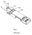
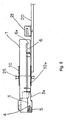
- Fig. 1 is a perspective view illustrating a conventional optical transceiver disclosed in U.S. Patent No. 6,434,015 with its bottom surface oriented upward.
- the conventional optical transceiver illustrated in Fig. 1 comprises housing 101 provided for accommodating a light emitting element and a light receiving element and formed with latch 114; and ejector 170 for removing latch 114 from a retaining hole (not shown) of a cage.
- Ejector 170 is arranged in an ejector sheet formed in lower portion 111 of housing 101, such that depression onto push plate 179 arranged at the rear end of ejector 170 enables the leading end of ejector 170 to extend to the vicinity of latch 114 from the interior of the ejector sheet.
- the leading end of ejector 170 protrudes while latch 114 of the optical transceiver is retained in the retaining hole formed through the spring plate of the cage, the spring plate is bent to release latch 114 from retention by the retaining hole.
- this optical transceiver can be withdrawn from the cage by pushing push plate 179 of ejector 170 in a direction indicated by arrow A in Fig. 1 to protrude the leading end thereof to the vicinity of latch 114, and releasing latch 114 from the retention by the retaining hole formed through the spring plate of the cage.
- Another optical module has been proposed by the applicant for permitting the user to remove the optical module from a cage through simple operations and for installing a plurality of the optical modules in a single communication device at higher density (refer to the Japanese patent application No. JP-2002-334967-A filed by the present applicant).
- Fig. 2 is a diagram illustrating an optical module described in patent application JP-2002-334967-A.
- the optical module described has a locking mechanism which comprises locking member 204 swingably attached to case 201 and having latch 204d for retention in retaining hole 201 a formed in cage 210; and lever 203 for moving locking member 204 to release latch 204d from retaining hole 210a in which latch 204d is retained.
- This locking mechanism is designed such that as the user pulls lever 203 forward of case 201, i.e., in a direction in which the optical module accommodated in cage 210 is withdrawn from cage 210, latch 204d retained in retaining hole 210a comes off retaining hole 201 a.
- a movable range of lever 203 is limited within a region forward of a front end surface of case 201.
- An SFP optical transceiver conforming to the MSA standard, as disclosed in Fig. 1, should have a height of about 10 mm and a width of about 14 mm, i.e., the SFP optical transceiver itself is small in size, so that ejector 170 (see Fig. 1) disposed in such a small optical transceiver must be a miniature component. For this reason, it must be a finger tip (or even a nail tip in some cases) that should depress push plate 179 of ejector 170 illustrated in Fig. 1.
- the locking mechanism for an optical module described in Fig. 2 is made up of two components which are the aforementioned locking member 204 and lever 203, however, such a locking mechanism is preferably made up of the least possible number of components from a view point of the tendency of reducing a material cost and the number of manufacturing steps of the optical module.
- the optical transceiver is typically small in size as mentioned above, and lever 203 is a miniature component. Such miniature structure forces the user to hold lever 203 with tips of fingers for manipulation . Thus, the user could more readily remove the optical transceiver if the optical transceiver could be unlocked from the cage without the need for manipulating such lever 203.
- the optical module illustrated in Fig. 2 limits the movable range of lever 203 within a region forward of the front end surface of case 201 to save the space required to install the optical module in a communication device, thereby making it possible to install a plurality of the optical modules in a communication device at a high density.
- lever 203 itself can be omitted from the optical module, a larger number of the optical modules can be installed in a communication device at higher density.
- an optical module comprises a case having a connection port for connection with an external optical fiber cable connector, and a locking member for locking the case in a cage for accommodating the case.
- the locking member is configured to lock the case in the cage when a connector is connected to the connection port after the case has been inserted into the cage up to a predetermined position, and to unlock the case from the cage when the connector is disconnected from the connection port.
- the case can be locked in the cage through a simple operation of inserting the connector into the connection port after the case has been inserted into the cage.
- the case is automatically locked in the cage only by inserting the connector into the connection port after the case has been inserted into the cage, so that the optical module can virtually omit the operation otherwise required for locking the case in the cage, thus facilitating the handling of the optical module. Consequently, the user can be prevented from forgetting to lock the case in the cage even if h e is not conscious of locking the case in the cage.
- the case may be unlocked from the cage only by disconnecting the connector from the connection port, resulting in elimination of the operation for unlocking the case, and consequent simplification of the operation for removing the optical module from the cage.
- the optical module cannot be withdrawn from the cage with the connector being kept connected to the connection port because the case is maintained to be locked in the cage when the connector is kept connected to the connection port. It is therefore possible to obviate the user from inadvertently withdrawing the optical module from the cage while the optical fiber cable connector is kept connected to the connection port to make a communication, thus preventing communication interrupted in the middle, or failure in the optical module.
- the locking member may include a shaft rotatably supported by the case, a first section positioned on one side of the shaft, and a second section positioned on another side of the shaft, and including a latch for retention by a retaining hole formed in the cage, and a shoulder abutted by the connector when the connector is connected to the connection port, wherein the locking member may be configured to pivotally move about the shaft to bring the latch into retention by the retaining hole as the second section is pressed by the connector in abutment to the shoulder.
- the connector presses the shoulder of the locking member, causing the locking member to pivotally move about the shaft to fit the latch into the retention hole, with the result that the case is locked in the cage.
- the locking member may be configured to pivotally move about the shaft as the first section is moved in a direction in which the first section is further away from the case, causing the latch retained in the retaining hole to come off the retaining hole
- the optical module may further include an urging member for urging the first section in the direction in which the first section is moved away from the case.
- Another optical module includes a case having a connection port for connection with an external optical fiber cable connector, and a locking member for locking the case in a cage for accommodating the case, wherein the locking member has a shaft rotatably supported by the case, a first section positioned on one side of the shaft, and a second section positioned on another side of the shaft, and including a latch for retention by a retaining hole formed in the cage, and a shoulder to which the connector abuts when the connector is connected to the connection port.
- the locking member is configured to pivotally move about the shaft to a position at which the latch is fitted into the retaining hole as the second section is pressed by the connector in abutment to the shoulder.
- the locking member is further configured to pivotally move about the shaft to a position at which the latch retained in the retaining hole comes off the retaining hole as the first section is moved in a direction in which the first section is further away from the case.
- the optical module further includes an urging member for urging the first section in the direction in which the first section is moved away from the case.
- the connector presses the shoulder of the locking member, causing the locking member to pivotally move about the shaft to fit the latch into the retaining hole, thereby locking the case in the cage.
- the first section of the locking member is urged by the urging member in the direction in which the first section is moved away from the cage, causing the locking member to pivotally move about the shaft to release the latch retained in the retaining hole from the retaining hole, thereby unlocking the case from the cage.
- the case can also be locked in the cage through a simple operation of inserting the connector into the connection port after the case has been inserted into the cage.
- the case is automatically locked in the cage only by inserting the connector into the connection port after the case has been inserted into the cage, so that the optical module can virtually omit the operation otherwise required for locking the case in the cage, thus facilitating the handling of the optical module. Consequently, the user can be prevented from forgetting to lock the case in the cage even if the user is not conscious of locking the case in the cage.
- the optical module cannot be withdrawn from the cage with the connector being kept connected to the connection port because the case is maintained to be locked by the cage when the connector is kept connected to the connection port. It is therefore possible to obviate the user from inadvertently withdrawing the optical module from the cage while the optical fiber cable connector is kept connected to the connection port to make a communication, thus preventing communications interrupted in the middle, or a failure in the optical module.
- the other optical module of the invention is similar in that the case is unlocked from the cage only by disconnecting the connector from the connection port, resulting in elimination of the operation for unlocking the case, and consequent simplification of the operation for removing the optical module from the cage.
- the locking member may be configured to act within a recessed groove space formed in the case.
- the locking member acts beyond the outer dimensions of the case, a plurality of optical modules, when installed in a single device, must be arranged at wider intervals in consideration of the movable range of the locking member, so that the optical modules cannot be installed in the device at high density.
- the locking member is configured to act only within the recessed groove space formed in the case, as proposed by the invention, the movable range of the locking member need not be taken into consideration when the optical modules are installed in a device, thus making it possible to arrange the optical modules at narrower intervals and consequently install a plurality of optical modules in the device at a higher density.
- the urging member may include a spring member.
- the locking member may be integrally formed with the spring member.
- the spring member and locking member may be made of a resin material.
- the locking member may be made of a metal material.
- the urging member may be made up of a pair of magnets disposed in the case and the first section, respectively, such that the same poles oppose each other.
- An optical module/cage assembly includes the optical module described above, a cage having the optical module inserted therein up to a predetermined position, and a dust cap having the same shape as the connector, and connected to the connection port formed in the optical module.
- the optical module can be locked in the cage with the connection port being closed by inserting the optical module into the cage up to the predetermined position, and inserting the dust cap into the connection port.
- the dust cap With the dust cap thus inserted into the connection port, it is possible to prevent the optical module from coming off the cage to be damaged during transportation, and fine dust possibly produced from a packing material from sticking to an optical unit within the optical module during transportation to inhibit the optical module from normally operating.
- a method of locking an optical module in a cage for accommodating the optical module according to the invention involves locking the optical module in the cage, wherein the optical module includes a case having a connection port for connection with an external optical fiber cable connector, and a locking member for locking the case in the cage, and the locking member includes a shaft rotatably supported by the case, a first section positioned on one side of the shaft, and a second section positioned on another side of the shaft, and including a latch for retention in a retaining hole formed in the cage, and a shoulder to which the connector abuts when the connector is connected to the connection port.
- the method includes the steps of inserting the case into the cage up to a predetermined position, connecting the connector to the connection port, pressing the second section with the connector in abutment to the shoulder to pivotally move the locking member about the shaft, and fitting the latch into the retaining hole.
- the case can be automatically locked in the cage only through a simple operation of inserting the connector into the connection port after the case has been inserted into the cage.
- a method of unlocking an optical module from a cage for accommodating the optical module according to the invention involves unlocking from the cage the optical module including a case having a connection port for connection with an external optical fiber cable connector, and a locking member for locking the case in the cage, wherein the locking member includes a shaft rotatably supported by the case, a first section positioned on one side of the shaft, and a second section positioned on another side of the shaft and including a latch for retention by a retaining hole formed in the cage, and a shoulder to which the connector abuts when the connector is connected to the connection port.
- the method includes the steps of disconnecting the connector connected to the connection port from the connection port, moving the first section in a direction in which the first section is further away from the case to pivotally move the locking member about the shaft, and releasing the latch retained in the retaining hole from the retaining hole.
- the locking member pivotally moves about the shaft to automatically unlock the case from the cage.
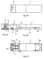
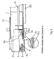
- Fig. 3A is a top plan view of the optical module
- Fig. 3B is a front view of the same
- Fig. 3C is a bottom view of the same
- Fig. 3D is a left side view of the same.
- Fig. 3B also illustrates the internal structure of the optical module for convenience of description.
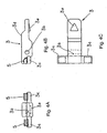
- Fig. 4A is a left side view of the locking member
- Fig. 4B is a front view of the same
- Fig. 4C is a bottom view of the same.
- the optical module of this embodiment comprises case 1 which defines the shape of the optical module; and locking member 3 attached to the bottom of case 1 near a front end surface.
- Case 1 contains printed circuit board 6 mounted with an optical unit (not shown) which includes a light emitting element and a light receiving element such as a laser diode (LD) and a photodiode (PD).
- Printed circuit board 6 has connection terminals 6a disposed on the right side (see Fig. 3B), as illustrated, on a rear edge thereof for connection with socket 21 (see Fig. 8) within cage 10 (see Fig. 7), later described, when case 1 is accommodated in cage 10.
- Case 1 also has connection port 2 which is open on the front end surface thereof for connection with optical fiber cable connector 15 (see Fig. 7). By inserting optical fiber cable connector 15 into connection port 1, optical fiber cable connector 15 can be connected to the optical module.
- the optical module according to this embodiment can be provided for any of transmission, reception, and transmission/reception of optical signals, and has at least one of a light emitting element and a light receiving element as mentioned above.
- Connection port 2 formed on the front end surface of case 1 is not limited in number.
- Recessed groove space 1 c is formed in a lower front portion of case 1 for receiving locking member 3.
- Shaft fixing holes 1 a are formed on both sides of recessed groove space 1 c of case 1 for fixing shaft 4 which pivotably supports locking member 3 on case 1.
- Locking member 3 is attached to case 1 by placing locking member 3 in recessed groove space 1 c of case 1, inserting shaft 4 through shaft fixing holes 1 a of case 1 and shaft receiving hole 3b of locking member 3, and fixing both ends of shaft 4 at respective shaft fixing holes 1 a with an adhesive or the like. In this event, shaft 4 should not be fixed to shaft receiving hole 3b of locking member 3. This allows locking member 3 to pivotally move about shaft 4.
- Locking member 3 comprises latch 3a which is retained in retaining hole 10a (see Fig. 7) of cage 10 when case 1 is accommodated in cage 10; shaft receiving hole 3b for shaft 4 inserted therethrough; spring seats 3c each having a top surface for fixing spring 5 thereon; and shoulder 3d to which connector 15 comes into abutment when connector 15 (see Fig. 7) is connected to connection port 2.
- first section a portion of locking member 3 in front of shaft receiving holes 3b (left-hand side in Fig. 4B)
- a portion of locking member behind shaft receiving holes 3b (right-hand side in Fig. 4B) is referred to as the "second section.”
- spring seats 3c are disposed in the first section of locking member 3, while latch 3a and shoulder 3d are disposed in the second section of the same.
- Spring seats 3c are disposed on both sides of the body of locking member 3.
- Spring 5 is fixed on the top surface of each spring seat 3c as an urging member for urging the first section of locking member 3 in a direction in which the first section is moved away from case 1. While a plate spring is illustrated in Figs. 4A and 4B as an implementation of spring 5, another spring member may be used for spring 5, including a coil spring and the like.
- Locking member 3 and spring 5 may be integrally molded, for example, by a molding process.
- a suitable material for these components may be a resin such as PPS (polyphenylene sulfide).
- locking member 3 may have been molded using a resin as mentioned above, such that spring 5 is subsequently attached onto each spring seat 3c of the molding.
- spring 5 can be made of a material different from that of locking member 3.
- only spring 5 can be made of a metal.
- locking member 3 may be formed by a die cast technique or the like.
- a suitable material in this technique may be a metal such as zinc, aluminum, or the like.
- locking member 3 may have been previously formed of a metal material as mentioned above, and spring 5 is subsequently attached onto each spring seat 3c of the molding.
- locking member 3 and shaft 4 are made as separate components, and after locking member 3 is placed in recessed groove space 1 c of case 1, shaft 4 is inserted through shaft fixing holes 1 a of case 1 and shaft receiving hole 3b of locking member 3, and both ends of shaft 4 are fixed to respective shaft fixing holes 1 a with an adhesive or the like to attach locking member 3 to case 1.
- the optical module of the present invention is not limited to locking member 3 and shaft 4 in this particular structure or to the structure for supporting locking member 3, provided by case 1. For example, as illustrated in Figs.
- locking member 3' may be integrally formed with shaft 4', and case 1 may be provided with a support which permits shaft 4' to be snap fitted thereon from the outside.
- case 1 may be provided with a support which permits shaft 4' to be snap fitted thereon from the outside.
- locking member 3 drawn by one-dot chain lines represents its posture when connector 15 (see Fig. 7) is not connected to connection port 2, while locking member 3 drawn by solid lines represents its posture when connector 15 is kept connected to connection port 2.
- each of springs 5 stretches between associated spring receiving surface 1 b formed on the bottom surface of case 1 and spring seat 3c to push down the first section including spring seats 3c.
- This causes locking member 3 to rotate about shaft 4 in the counter-clockwise direction in the figure to lift up the second section of locking member 3 including latch 3a and shoulder 3d into recessed groove space 1 c of case 1, thereby bringing locking member 3 into the posture represented by the one-dot chain lines in Fig. 6.
- connection port 2 As connector 15 is connected to connection port 2, the bottom surface of connector 15 comes into abutment to shoulder 3d of locking member 3 to push down the second section of locking member 3, thereby bringing locking member 3 into the posture represented by the solid lines in Fig. 6.
- the first section of locking member 3 including spring seats 3c rotates about the shaft 4 in the clockwise direction in the figure to narrow down the spacings between respective spring seats 3c and spring receiving surfaces 1b, causing springs 5 to contract.
- Each of springs 5 used in this embodiment generates an urging force just enough to maintain locking member 3 in the posture represented by the one-dot chain lines when connector 15 is not connected to connection port 2, and therefore generates a slight amount of force by its compression. As such, the user can connect connector 15 to connection port 2 without substantially feeing repellent forces of springs 5.
- Locking member 3 in this embodiment is designed to act within recessed groove space 1 c of case 1.
- locking member 3 acts beyond the outer dimensions of case 1, a plurality of optical modules, when installed in a single device, must be arranged at wider intervals in consideration of the movable range of each locking member 3, so that the optical modules cannot be installed in the device at a high density.
- the action of locking member 3 is limited within recessed groove space 1 c of case 1 as in this embodiment, the movable range of locking member 3 need not be taken into consideration when the optical modules are installed in a device, thus making it possible to arrange the optical modules at narrower intervals and consequently install a plurality of the optical modules in the device at a higher density.
- spring 5 has been exemplified by a plate spring in the foregoing description, another spring member can be used for spring 5 instead of the plate spring, including a coil spring and the like.
- springs 5 may be replaced with a pair of magnets disposed in spring seats 3c and spring receiving surfaces 1 b such that the same poles face each other, respectively, thereby providing an urging member between spring seats 3c and spring receiving surfaces 1 b.
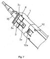
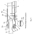
- Fig. 7 is a perspective view, taken from below, and
- Fig. 8 in turn is a front view also showing the internal structure of the optical module for convenience of description.
- Cage 10 for accommodating case 1 of the optical module has retaining hole 10a on its bottom surface. Retaining hole 10a is arranged at a position at which latch 3a of locking member 3 is retained thereby when case 1 is inserted into cage 10.
- Cage 10 which is placed on mother board 20 within a communication device or the like, has part thereof projecting from an opening formed through front panel 25 of the communication device or the like.
- Socket 21 mounted on mother board 20 is disposed at the rear end within cage 10. Connected to socket 21 are connection terminals 6a of printed circuit board 6 within case 1, when case 1 is accommodated in cage 10.
- Cage 10 may be made by bending a plate made of a metal, for example, stainless steel (SUS) or the like.
- case 1 may also be made by bending a plate made of a metal such as stainless steel (SUS).
- case 1 may be fabricated by molding using a resin such as PPS (polyphenylene sulphide) in a manner similar to locking member 4.
- Fig. 9 illustrates the optical module which is accommodated in cage 10.
- connection terminals 6a see Fig. 8 of printed board 6 within case 1 are kept connected to socket 21 (see Fig. 8) on mother board 20.
- connector 15 has not been inserted into connection port 2, with locking member 3 having latch 3a not retained by retaining hole 10a of cage 10, so that case 1 is not locked in cage 10.
- connection port 2 of case 1 As connector 15 is inserted halfway into connection port 2 of case 1, the resulting state is shown in Fig. 10. In this event, the bottom surface of a leading end portion of connector 15 is coming into abutment to shoulder 3d on the top surface of locking member 3. As connector 15 is further inserted deeply into connection port 2 from the state shown in Fig. 10, shoulder 3d of locking member 3 is gradually pushed down by the leading end of connector 15, causing locking member 3 to rotate about shaft 4 in the clockwise direction.
- Fig. 11 illustrates connector 15 fully inserted into connection port 2 of case 1.
- shoulder 3d of locking member 3 is completely pushed down by the bottom surface of connector 15.
- latch 3a of locking member 3 is fitted into retaining hole 10a of cage 10, thereby locking case 1 by cage 10.
- latch 15b of connector 15 is retained by retaining hole 10a in connection port 2, causing optical fiber end 15a projecting from the leading end of connector 15 to be connected to an optical unit (not shown) on printed board 6.
- connection port 2 when connector 15 is kept connected to connection port 2, case 1 is locked in cage 10, so that the optical module cannot be removed from cage 10 with connector 15 kept connected to connection port 2. It is therefore possible to obviate the user from inadvertently withdrawing the optical module from cage 10 while optical fiber cable connector 15 is kept connected to connection port 2 to make a communication, thus preventing communication interrupted in the middle, or failure in the optical module.
- Fig. 12 is a diagram illustrating operations involved in withdrawing optical module from cage 10.
- connector 15 is first removed from connection port 2 of case 1 in a direction indicated by an arrow B.
- the rotation causes latch 3a to lift up and come off retaining hole 10a, thereby releasing latch 3a from the retention by retaining hole 10a.
- case 1 is withdrawn in a direction indicated by arrow C after latch 3a has been released from the retention by retaining hole 10a in this manner, the optical module can be removed from cage 10.
- latch 3a can be retained in retaining hole 10a of cage 10 to lock case 1 in cage 10 through simple operations of inserting case 1 into cage 10 and then inserting connector 15 into connection port 2.
- case 1 is automatically locked in cage 10 only by inserting connector 15 into connection port 2 after case 1 has been inserted into cage 10, so that the optical module can virtually omit the operation otherwise required for locking case 1 in cage 10, thus facilitating the handling of the optical module. Consequently, the user can be prevented from forgetting to lock case 1 in cage 10 even if the user is not conscious of locking case 1 in cage 10.
- latch 3a is released from the retention by retaining hole 10a only by disconnecting connector 15 from connection port 2, resulting in elimination of the operation for releasing the retention and in consequent simplification of the operation for removing the optical module from cage 10.
- locking member 3 acts within recessed groove space 1 c of case 1, so that even if a plurality of optical modules are arranged vertically and horizontally adjacent to one another, locking member 3 of certain optical module will not interfere with other optical modules. It is therefore possible to install a plurality of optical modules in a communication device or the like at higher density.
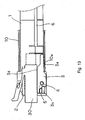
- Fig. 13 shows the optical module when it is in distribution.
- the optical is accommodated in cage 10 when it is shipped for sale. For this reason, the optical module is inserted into cage 10 before packing, but the optical module could come off cage 10 and be damaged during transportation unless the optical module is locked in cage 10.
- the optical module is packed with connection port 2 of case 1 being left open, fine dust possibly produced by packing material and the like during transportation could stick to the optical unit (not shown) within the optical module, possibly inhibiting the optical module from normally operating. Therefore, the optical module is preferably packed after it is locked in cage 10 with connection port 2 being closed.
- the optical module of this embodiment can be locked in cage 10 with connection port 2 being closed by inserting the optical module into cage 10, and connecting to connection port 2 dust cap 30 which has the same shape as connector 15 (see Fig. 10 or the like) of the type connected to connection port 2.
- dust cap 30 when dust cap 30 is inserted into connection port 2 of an unused optical module, to which optical fiber connector 15 is not connected, among optical modules mounted in associated cages 10 of a communication device or the like, dust cap 30 functions as a stopper for preventing the optical module from dropping from the communication device or the like.
Landscapes
- Physics & Mathematics (AREA)
- General Physics & Mathematics (AREA)
- Optics & Photonics (AREA)
- Optical Couplings Of Light Guides (AREA)
Applications Claiming Priority (2)
| Application Number | Priority Date | Filing Date | Title |
|---|---|---|---|
| JP2003154705A JP4117476B2 (ja) | 2003-05-30 | 2003-05-30 | 光モジュール、光モジュールとケージとの組立体、光モジュールとケージとのロック方法及びロック解除方法 |
| JP2003154705 | 2003-05-30 |
Publications (2)
| Publication Number | Publication Date |
|---|---|
| EP1482340A2 true EP1482340A2 (fr) | 2004-12-01 |
| EP1482340A3 EP1482340A3 (fr) | 2005-04-13 |
Family
ID=33128317
Family Applications (1)
| Application Number | Title | Priority Date | Filing Date |
|---|---|---|---|
| EP04090212A Withdrawn EP1482340A3 (fr) | 2003-05-30 | 2004-05-28 | Module optique capable de faciliter l'état de déverrouillage avec une cage qui contient le module optique. |
Country Status (6)
| Country | Link |
|---|---|
| US (1) | US7347633B2 (fr) |
| EP (1) | EP1482340A3 (fr) |
| JP (1) | JP4117476B2 (fr) |
| KR (1) | KR100637636B1 (fr) |
| CN (2) | CN101482636A (fr) |
| TW (1) | TWI231626B (fr) |
Cited By (1)
| Publication number | Priority date | Publication date | Assignee | Title |
|---|---|---|---|---|
| US6644810B1 (en) | 1999-01-22 | 2003-11-11 | Haag-Streit Ag | Ophthalmic apparatus with a lighting and/or beam therapy ray whose surface intensity distribution can be regulated and device with such an apparatus for eye treatment |
Families Citing this family (26)
| Publication number | Priority date | Publication date | Assignee | Title |
|---|---|---|---|---|
| US7287916B2 (en) * | 2004-10-28 | 2007-10-30 | Sumitomo Electric Industries, Ltd. | Optical pluggable transceiver |
| JP4915377B2 (ja) * | 2007-06-20 | 2012-04-11 | 日立電線株式会社 | 光トランシーバ |
| JP5332582B2 (ja) * | 2008-12-16 | 2013-11-06 | 日本電気株式会社 | 光モジュール及びロック解除部材、ロック解除方法 |
| US8814229B2 (en) * | 2010-04-30 | 2014-08-26 | Finisar Corporation | Latching mechanism for an electronic module |
| CN102298426B (zh) * | 2010-06-28 | 2016-08-24 | 上海力锐网络科技有限公司 | 抽拉式固定结构 |
| CN102141659B (zh) * | 2010-08-11 | 2013-11-06 | 华为技术有限公司 | 光模块 |
| JP2012194451A (ja) * | 2011-03-17 | 2012-10-11 | Nec Corp | 光モジュールのロック機構 |
| US8724955B2 (en) * | 2011-04-07 | 2014-05-13 | Renaud Lavoie | Ejection mechanism and actuator for small form factor pluggable unit |
| KR101321785B1 (ko) * | 2011-12-21 | 2013-10-28 | 한국몰렉스 주식회사 | 슬라이드 타입 커넥터 |
| US8781284B2 (en) * | 2012-08-01 | 2014-07-15 | Leviton Manufacturing Co., Inc. | Low profile copper and fiber optic cassettes |
| US9309908B2 (en) | 2012-11-08 | 2016-04-12 | Finisar Corporation | Communication module latching mechanism |
| JP5517272B1 (ja) * | 2012-12-27 | 2014-06-11 | 日本航空電子工業株式会社 | コネクタ |
| CN104614821B (zh) * | 2015-02-14 | 2016-05-04 | 深圳市摩泰光电有限公司 | 压合式解锁装置及其rj45电口sfp模块 |
| CN105278053B (zh) * | 2015-03-23 | 2017-06-16 | 深圳市物联光通创新科技发展有限公司 | 一种塑料光纤收发器的结构装置 |
| US10468794B2 (en) * | 2015-07-30 | 2019-11-05 | Hewlett Packard Enterprise Development Lp | Transceiver module |
| US9690064B2 (en) | 2015-11-10 | 2017-06-27 | Leviton Manufacturing Co., Ltd. | Multi-gang cassette system |
| CN106850067B (zh) * | 2017-02-14 | 2019-07-16 | 青岛海信宽带多媒体技术有限公司 | 光模块及光模块的信号处理方法 |
| US10295773B2 (en) | 2017-03-29 | 2019-05-21 | Leviton Manufacturing Co., Inc. | Segregated fiber in a splice cassette |
| WO2019006121A1 (fr) * | 2017-06-28 | 2019-01-03 | Corning Research & Development Corporation | Ports d'extension de fibre optique, ensembles et procédés de fabrication associés |
| WO2019104059A1 (fr) * | 2017-11-21 | 2019-05-31 | Molex, Llc | Connecteur d'entrée/sortie claveté |
| US10840640B1 (en) * | 2019-07-18 | 2020-11-17 | Optoway Technology Inc. | Pluggable connector |
| KR102263279B1 (ko) * | 2020-06-29 | 2021-06-14 | (주)태양유니스 | 정보통신용 광케이블 고정장치 |
| WO2022178317A1 (fr) | 2021-02-18 | 2022-08-25 | Commscope Technologies Llc | Système de panneau de communication |
| US11971598B2 (en) | 2021-02-18 | 2024-04-30 | Commscope Technologies Llc | Tray arrangements for cassettes |
| US11811163B2 (en) | 2021-02-26 | 2023-11-07 | Leviton Manufacturing Co., Inc. | Mutoa and quad floating connector |
| TWI810912B (zh) * | 2022-04-26 | 2023-08-01 | 劉炫圻 | 具有栓鎖機構的殼體結構及具有該殼體結構的光纖收發器 |
Citations (5)
| Publication number | Priority date | Publication date | Assignee | Title |
|---|---|---|---|---|
| DE10055683A1 (de) * | 2000-11-03 | 2002-05-29 | Infineon Technologies Ag | Vorrichtung zum Entriegeln eines in eine Aufnahmevorrichtung einsteckbaren elektronischen Bauelements |
| US20020150344A1 (en) * | 2001-04-14 | 2002-10-17 | Chiu Liew C. | Pull-action de-latching mechanisms for fiber optic modules |
| US20020167793A1 (en) * | 2001-05-10 | 2002-11-14 | International Business Machines Corporation | Module having a latch |
| US6533603B1 (en) * | 2001-10-04 | 2003-03-18 | Finisar Corporation | Electronic module having an integrated latching mechanism |
| EP1477834A1 (fr) * | 2003-05-16 | 2004-11-17 | NEC Corporation | Module optique capable de faciliter le déverouillage d'un état verrouillé à un boítier hébergeant ledit module |
Family Cites Families (12)
| Publication number | Priority date | Publication date | Assignee | Title |
|---|---|---|---|---|
| JPH07231296A (ja) | 1994-02-21 | 1995-08-29 | Hitachi Cable Ltd | 光送受信器、光送信器及び光受信器 |
| GB2297007B (en) | 1995-01-13 | 1999-05-05 | Methode Electronics Inc | Removable transceiver module and receptacle |
| AU1331497A (en) * | 1995-12-18 | 1997-07-14 | Kerisma Medical Products, L.L.C. | Fiberoptic-guided interstitial seed manual applicator and seed cartridge |
| EP0916978B1 (fr) * | 1997-11-13 | 2009-04-22 | Diamond SA | Dispositif connecteur pour une connexion optique à tiroir |
| US6081647A (en) * | 1998-01-05 | 2000-06-27 | Molex Incorporated | Fiber optic connector receptacle |
| US6186670B1 (en) * | 1998-06-02 | 2001-02-13 | Pirelli Cable Corporation | Optical fiber connector module |
| DE59907236D1 (de) | 1999-02-12 | 2003-11-06 | Huber & Suhner Ag Herisau | Optischer steckverbinder |
| JP3362014B2 (ja) * | 1999-06-29 | 2003-01-07 | エヌイーシートーキン株式会社 | ケーブルコネクタのロック、アンロック構造及びロック、アンロック方法 |
| JP2001208935A (ja) * | 2000-01-24 | 2001-08-03 | Fujitsu Ltd | 光コネクタの接続構造 |
| CA2342003A1 (fr) * | 2000-03-24 | 2001-09-24 | Tyco Electronics | Adaptateur blinde |
| US6877906B2 (en) * | 2002-08-30 | 2005-04-12 | Nippon Telegraph And Telephone | Optical fiber cross-connect with a connection block, an alignment block and a handling device |
| US6726369B1 (en) * | 2003-03-11 | 2004-04-27 | Itt Manufacturing Enterprises, Inc. | Field repairable, breakaway housing for optical fiber connector |
-
2003
- 2003-05-30 JP JP2003154705A patent/JP4117476B2/ja not_active Expired - Fee Related
-
2004
- 2004-05-25 TW TW093114744A patent/TWI231626B/zh not_active IP Right Cessation
- 2004-05-25 US US10/852,112 patent/US7347633B2/en not_active Expired - Fee Related
- 2004-05-28 EP EP04090212A patent/EP1482340A3/fr not_active Withdrawn
- 2004-05-31 CN CNA200810212895XA patent/CN101482636A/zh active Pending
- 2004-05-31 KR KR1020040039077A patent/KR100637636B1/ko not_active IP Right Cessation
- 2004-05-31 CN CNA2004100464445A patent/CN1574495A/zh active Pending
Patent Citations (5)
| Publication number | Priority date | Publication date | Assignee | Title |
|---|---|---|---|---|
| DE10055683A1 (de) * | 2000-11-03 | 2002-05-29 | Infineon Technologies Ag | Vorrichtung zum Entriegeln eines in eine Aufnahmevorrichtung einsteckbaren elektronischen Bauelements |
| US20020150344A1 (en) * | 2001-04-14 | 2002-10-17 | Chiu Liew C. | Pull-action de-latching mechanisms for fiber optic modules |
| US20020167793A1 (en) * | 2001-05-10 | 2002-11-14 | International Business Machines Corporation | Module having a latch |
| US6533603B1 (en) * | 2001-10-04 | 2003-03-18 | Finisar Corporation | Electronic module having an integrated latching mechanism |
| EP1477834A1 (fr) * | 2003-05-16 | 2004-11-17 | NEC Corporation | Module optique capable de faciliter le déverouillage d'un état verrouillé à un boítier hébergeant ledit module |
Cited By (1)
| Publication number | Priority date | Publication date | Assignee | Title |
|---|---|---|---|---|
| US6644810B1 (en) | 1999-01-22 | 2003-11-11 | Haag-Streit Ag | Ophthalmic apparatus with a lighting and/or beam therapy ray whose surface intensity distribution can be regulated and device with such an apparatus for eye treatment |
Also Published As
| Publication number | Publication date |
|---|---|
| JP4117476B2 (ja) | 2008-07-16 |
| EP1482340A3 (fr) | 2005-04-13 |
| US7347633B2 (en) | 2008-03-25 |
| JP2004354866A (ja) | 2004-12-16 |
| CN101482636A (zh) | 2009-07-15 |
| TWI231626B (en) | 2005-04-21 |
| KR100637636B1 (ko) | 2006-10-23 |
| US20040240792A1 (en) | 2004-12-02 |
| CN1574495A (zh) | 2005-02-02 |
| KR20040103482A (ko) | 2004-12-08 |
| TW200507371A (en) | 2005-02-16 |
Similar Documents
| Publication | Publication Date | Title |
|---|---|---|
| US7347633B2 (en) | Optical module capable of facilitating release from locking state with cage which accommodates optical module | |
| EP1477834B1 (fr) | Module optique capable de faciliter le déverouillage d'un état verrouillé à un boîtier hébergeant ledit module | |
| US7281863B2 (en) | Module connect/disconnect structure and method for disconnecting a module using the structure | |
| US7201520B2 (en) | Optical module having a simple mechanism for releasing from a cage | |
| US8814229B2 (en) | Latching mechanism for an electronic module | |
| US6887092B2 (en) | Optical module locking mechanism for locking optical module case and cage for housing case to each other | |
| JP5085694B2 (ja) | 光コネクタ | |
| US20110170832A1 (en) | Optical transceiver module and method of manufacturing the optical transceiver module | |
| JP3455168B2 (ja) | レセプタクルモジュール | |
| US6885560B2 (en) | Pluggable optical transceiver with push-pull actuator handle | |
| US9354407B2 (en) | Biasing assembly for a latching mechanism | |
| JP2011048174A (ja) | 着脱工具 | |
| US7204710B1 (en) | SFP module mounting structure | |
| US7837400B2 (en) | Optoelectronic transceiver assembly and release mechanism employed therein | |
| US7556436B2 (en) | Optical connector system | |
| JP4306522B2 (ja) | 光モジュールの係止解除機構、光モジュール、および光モジュールとケージとの係止状態を解除する方法 | |
| US20050227518A1 (en) | Pluggable transceiver with cover resilient member | |
| KR100640357B1 (ko) | 플러그형 광송수신 모듈 어셈블리 | |
| JP5332582B2 (ja) | 光モジュール及びロック解除部材、ロック解除方法 | |
| JP4158579B2 (ja) | ロック機構付きパッケージ | |
| JP2006269442A (ja) | ロック機構及びモジュールのロック解除方法 | |
| JP2005338247A (ja) | 光モジュールの係止解除機構、光モジュール、および光モジュールとケージとの係止状態を解除する方法 | |
| WO2009118841A1 (fr) | Obturateur optique | |
| CN115903148A (zh) | 光收发装置及其退壳机构 | |
| JP2013045059A (ja) | 光トランシーバ |
Legal Events
| Date | Code | Title | Description |
|---|---|---|---|
| PUAI | Public reference made under article 153(3) epc to a published international application that has entered the european phase |
Free format text: ORIGINAL CODE: 0009012 |
|
| AK | Designated contracting states |
Kind code of ref document: A2 Designated state(s): AT BE BG CH CY CZ DE DK EE ES FI FR GB GR HU IE IT LI LU MC NL PL PT RO SE SI SK TR |
|
| AX | Request for extension of the european patent |
Extension state: AL HR LT LV MK |
|
| PUAL | Search report despatched |
Free format text: ORIGINAL CODE: 0009013 |
|
| RTI1 | Title (correction) |
Free format text: OPTICAL MODULE CAPABLE OF FACILITATING RELEASE FROM LOCKING STATE WITH CAGE WHICH ACCOMMODATES OPTICAL MODULE |
|
| AK | Designated contracting states |
Kind code of ref document: A3 Designated state(s): AT BE BG CH CY CZ DE DK EE ES FI FR GB GR HU IE IT LI LU MC NL PL PT RO SE SI SK TR |
|
| AX | Request for extension of the european patent |
Extension state: AL HR LT LV MK |
|
| RIC1 | Information provided on ipc code assigned before grant |
Ipc: 7H 01R 13/627 B Ipc: 7G 02B 6/42 A |
|
| 17P | Request for examination filed |
Effective date: 20050414 |
|
| AKX | Designation fees paid |
Designated state(s): DE FR GB IT |
|
| STAA | Information on the status of an ep patent application or granted ep patent |
Free format text: STATUS: THE APPLICATION IS DEEMED TO BE WITHDRAWN |
|
| 18D | Application deemed to be withdrawn |
Effective date: 20111201 |