EP1481874A2 - Système de direction et méthode de commande associe pour un véhicule - Google Patents
Système de direction et méthode de commande associe pour un véhicule Download PDFInfo
- Publication number
- EP1481874A2 EP1481874A2 EP20040253070 EP04253070A EP1481874A2 EP 1481874 A2 EP1481874 A2 EP 1481874A2 EP 20040253070 EP20040253070 EP 20040253070 EP 04253070 A EP04253070 A EP 04253070A EP 1481874 A2 EP1481874 A2 EP 1481874A2
- Authority
- EP
- European Patent Office
- Prior art keywords
- steering
- turning
- clutch
- section
- steer
- Prior art date
- Legal status (The legal status is an assumption and is not a legal conclusion. Google has not performed a legal analysis and makes no representation as to the accuracy of the status listed.)
- Granted
Links
Images


Classifications
-
- B—PERFORMING OPERATIONS; TRANSPORTING
- B62—LAND VEHICLES FOR TRAVELLING OTHERWISE THAN ON RAILS
- B62D—MOTOR VEHICLES; TRAILERS
- B62D6/00—Arrangements for automatically controlling steering depending on driving conditions sensed and responded to, e.g. control circuits
- B62D6/08—Arrangements for automatically controlling steering depending on driving conditions sensed and responded to, e.g. control circuits responsive only to driver input torque
- B62D6/10—Arrangements for automatically controlling steering depending on driving conditions sensed and responded to, e.g. control circuits responsive only to driver input torque characterised by means for sensing or determining torque
-
- B—PERFORMING OPERATIONS; TRANSPORTING
- B62—LAND VEHICLES FOR TRAVELLING OTHERWISE THAN ON RAILS
- B62D—MOTOR VEHICLES; TRAILERS
- B62D1/00—Steering controls, i.e. means for initiating a change of direction of the vehicle
- B62D1/02—Steering controls, i.e. means for initiating a change of direction of the vehicle vehicle-mounted
- B62D1/16—Steering columns
- B62D1/163—Part of the steering column replaced by flexible means, e.g. cable or belt
-
- B—PERFORMING OPERATIONS; TRANSPORTING
- B62—LAND VEHICLES FOR TRAVELLING OTHERWISE THAN ON RAILS
- B62D—MOTOR VEHICLES; TRAILERS
- B62D5/00—Power-assisted or power-driven steering
- B62D5/001—Mechanical components or aspects of steer-by-wire systems, not otherwise provided for in this maingroup
- B62D5/003—Backup systems, e.g. for manual steering
-
- B—PERFORMING OPERATIONS; TRANSPORTING
- B60—VEHICLES IN GENERAL
- B60Y—INDEXING SCHEME RELATING TO ASPECTS CROSS-CUTTING VEHICLE TECHNOLOGY
- B60Y2400/00—Special features of vehicle units
- B60Y2400/30—Sensors
- B60Y2400/301—Sensors for position or displacement
Definitions
- the present invention relates to a technique of, so-called, steer-by-wire type steering apparatus and method for an automotive vehicle in which a clutch to link a steering input section to steered road wheels which are mechanically separated is interposed midway through a steering system from the steering input section to the steered road wheels.
- Japanese Patent Application First Publication No. 2002-145098 published on May 22, 2002 (which corresponds to a United States Patent No. 6,442,462 issued on April 27, 2002) exemplifies a previously proposed steering system of the steer-by-wire type.
- a torque sensor is interposed between a steering wheel and a reaction motor.
- the clutch is connected so that a steering force with a vehicle driver directly turns (steers) tire (or road) wheels and a torque assistance control (power steering) by means of a controllable motor according to a signal of the torque sensor.
- an object of the present invention to provide steering apparatus and method for an automotive vehicle which are capable of providing an optimum assistance torque during the connection of the clutch, according to an estimation of the steering torque using a steering angle sensor and a turning angle sensor which are already installed in a system although the system is a low cost effectiveness and a space saving without installation of the torque sensor installed in proximity to the steering input section.
- a steering apparatus for an automotive vehicle comprising: an operation portion having an operation input section; a turning section that turns steered road wheels; a clutch installed in a predetermined position in a midway through a steering system from the operation input section to the steered road wheels to link between the operation input section and the steered road wheels; a steering angle detecting section installed in the operation portion to detect a steering angle of the operation portion; a turning angle detecting section installed in the turning section that detects a turning angle; an elastically deformable member interposed between the operation portion and the turning portion that transmits a steering torque inputted from the operation input section to the steered road wheels when the clutch causes the operation input section and the steered road wheels to be connected; and an angular deviation calculating section that calculates an angular deviation between the steering angle detection value and the turning angle detection value developed due to the deformation of the elastically deformable member.
- a steering method for an automotive vehicle comprising: providing an operation portion having an operation input section; providing a turning section that turns steered road wheels; providing a clutch installed in a predetermined position in a midway through a steering system from the operation input section to the steered road wheels to link between the operation input section and the steered road wheels; detecting a steering angle of the operation portion; detecting a turning angle; providing an elastically deformable member interposed between the operation portion and the turning section that transmits a steering torque inputted from the operation input section to the steered road wheels when the clutch causes the operation input section and the steered road wheels to be connected; and calculating an angular deviation between the steering angle detection value and the turning angle detection value developed due to the deformation of the elastically deformable member.
- Fig. 1 is a whole configuration view of a steering apparatus in a first preferred embodiment according to the present invention.
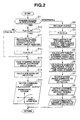
- Fig. 2 is an operational flowchart representing a steer-by-wire control process executed by a steer-by-wire controller (SBW controller) shown in Fig. 1.
- SBW controller steer-by-wire controller
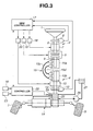
- Fig. 3 is a whole configuration view of the steering apparatus in a second preferred embodiment according to the present invention.
- Fig. 4 is an operational flowchart representing a steer-by-wire control process executed by the steer-by-wire controller shown in Fig. 3.
- Fig. 1 shows a whole system configuration view of a vehicular steering apparatus in a preferred embodiment according to the present invention.
- a tuning actuator of a steer-by-wire system hereinafter also referred to as an SBW system
- SBW system steer-by-wire system
- duplex system for a fail safe purpose is exemplified.
- a steering wheel (a steering input section) 1 is installed within a vehicular passenger compartment (not shown).
- a reference numeral 2 denotes an operation portion.
- a reference numeral 3 denotes steered road wheels and a reference numeral 4 denotes a turning section.
- a reference numeral 5 denotes a clutch.
- a reference numeral 6 denotes a steering angle sensor.
- a reference numeral 7 denotes a reaction force actuator.
- a reference numeral 8 denotes steering angle sensor.
- a reference numeral9 denotes a second column shaft (steering axle).
- a reference numeral 10 denotes a fist turning (angle) actuator.
- a reference numeral 11 denotes a second turning (angle) actuator and a reference numeral 12 denotes a pinion angle sensor (turning angle sensor).
- a reference numeral 13 denotes a pinion shaft (turning angle axle).
- a reference numeral 14 denotes a steering mechanism.
- a reference numeral 15 denotes a cable mechanism.
- a reference numeral 16 denotes a vehicle speed sensor.
- a reference numeral 17 denotes a steer-by-wire controller.
- a reference numeral 18 denotes a reaction force actuator drive circuit and a reference numeral 19 denotes a clutch drive circuit.
- a reference numeral 20 denotes a first turning actuator drive circuit.
- a reference numeral 21 denotes a second turning actuator drive circuit.
- the steering apparatus in the first embodiment includes: operation portion 2 having steering wheel 1; turning section 4 to turn the steered road wheels 3 and 3; and clutch 5 linking steering wheel 1 to steered wheels 3 and 3 which are mechanically separated.
- First column shaft 8 of operation part 2 is provided with steering wheel 1, steering angle sensor 6, and reaction force actuator 7.
- Clutch 5 is constituted by an electromagnetic clutch which can control connection and release from an external and is interposed between first column shaft 8 and second column shaft 9 of operational portion 2.
- Pinion shaft 13 of turning section 4 is provided with first turning actuator 10, second turning actuator 11, and pinion angle sensor 12.
- a steering mechanism 14 of a rack-and-pinion type is linked.
- Steered road wheels (non-driven wheels) 3 and 3 are interposed between both sides of steering mechanism 14 whose turning angles can be varied in accordance with a movement of a rack gear axle.
- Cable mechanism 15 includes: two cables 15c and 15d extended between operational portion 2 and turning portion 4 which are examples of low-rigidity members (which can extend (an elastic deformation is possible) due to a steering torque transmitted during a time at which clutch 5 is connected; a first cable reel 15a disposed on a lower end of second column shaft 9; and a second cable reel 15b disposed on an upper end of pinion shaft 13.
- Two cables 15c and 15d serve to link both cable reels 15a and 15b when they are respectively wound on the respective cable reels mutually in opposite directions.
- Steer-by-wire (SBW) controller 17 receives various sensor signals from steering angle sensor 6, pinion angle sensor 12, and vehicle speed sensor 16, and controls reaction force actuator 7, clutch 5 installed on operation portion 2, first turning actuator 10 and second turning actuator 11 disposed on turning section 4, these actuators 7, 10, 11, and clutch 5.
- Steer-by-wire controller 17 is provided with a fail safe control section that outputs a command to connect clutch 5 when a failure occurs in SBW system and outputs a command to obtain an assistance torque in accordance with an angle deviation between the calculated steering angle and turning angle to at least one of two turning actuators 10 and 11 (namely, a normal actuator).
- Fig. 2 shows an operational flowchart executed by means of steer-by-wire controller 17 in the first embodiment and representing a steer-by-wire control procedure.
- SBW controller 17 determines whether SBW system has failed according to diagnosis analysis of respective drive circuits 18, 19, 20, and 21. If No (Normal), the routine goes to a step S2. If Yes (Failure), the routine goes to a step S10. At step S2, SBW controller 17 maintains the release of clutch 5 released or releases connected clutch 5 and the routine goes to a step S3. At step S3, SWB controller 17 resets a clutch flag FLG CL to zero representing that clutch 5 is released and the routine goes to a step S4. At step S4, SWB controller 17 reads sensor signals from steering angle sensor 6, pinion angle sensor 12, vehicle speed sensor 16 and the routine goes to a step S5.
- SWB controller 17 calculates a steering (angle) ratio (a ratio between the steering angle and the turning angle) by means of a map or calculation in accordance with the steering angle and turning angle to calculate a target turning angle and the routine goes to a step S6.
- SBW controller 17 calculates an optimum target steering reaction torque in accordance with the steering situation and vehicular state from the steering angle and vehicle speed and the routine goes to a step S7.
- SWB controller 17 outputs a command to coincide an actual turning angle with the target turning angle to first turning actuator 10 and the routine goes to a step S8.
- SBW controller 17 outputs a command to obtain the target turning angle and the routine goes to a step S9. Then, two turning actuators 10 and 11 cause the angular control for the steering system using the two turning actuators. Hence, the current value to obtain the required torque needed to turn steered road wheels 3 and 3 is distributed to two turning actuators 10 and 11. For example, the current value corresponds to the torque which is half of that required to turn the vehicle per turning actuator.
- SBW controller 17 outputs the command to obtain the steering reaction torque calculated at step S8 for reaction force actuator 7 and, then, the routine returns to RETURN.
- SWB controller 17 determines whether flag FLG CL is reset to " 0 ". If Yes at step S10, the routine goes to a step S11. If No at step S10, the routine goes to a step S13. At step S13, SBW controller 17 reads steering angle sensor 6 and pinion angle sensor 12 and the routine goes to a step S14. At step S14, SWB controller 17 calculates an angular deviation between the turning angle detection value based on the pinion angle sensor signal and the steering angle detection value based on the steering angle sensor signal and the routine goes to a step S15 (constituting angular deviation calculating section)
- SBW controller 17 calculates a motor command current using an assistance torque map described in brackets within step S15 and outputs this motor command current to at least one of first and second turning actuators 10 and 11 and is returned to RETURN. If the motor command currents are supplied to both of first and second turning actuators 10 and 11, it is possible to perform the actuators in the same manner as the normal operation time. In a case where either of the turning actuators 10 and 11 is outputted, a torque required to turn steered road wheels 3 and 3 by means of one of the turn actuators is obtained.
- an assistance torque map is set in such a way that, in a small angular deviation region, as the angular deviation becomes large, the assistance torque is proportionally increased and as the angular deviation further becomes large, a gradient of increase in the assistance torque becomes small.
- the assistance torque map may be such a map that, as the angular deviation and vehicle speed are varied, the assistance torque may be varied or may be such a map that the assistance torque is varied in accordance with the angular deviation and other vehicle drive states.
- step S1 When SBW system is normally operated, the flowchart of Fig. 2 indicates such a flow as step S1 ⁇ step S2 ⁇ step S3 ⁇ step S4 ⁇ step S5 ⁇ step S6 ⁇ step S7 ⁇ step S8 ⁇ step S9.
- a release control such as a clutch 5 installed within operational portion 2 (step S2), an angular control for first turning actuator 10 and for second turning actuator 11 installed on turning section 4 (steps S7 and S8), and a steering reaction force control (step S9) against reaction actuator 7 installed within operational portion 2 are carried out.
- steered road wheels 3 and 3 can be turned according to an optimum steering ratio in accordance with manipulated variable (steering angular displacement) and manipulation speed (or a steering angular velocity) for steering wheel 1 of the vehicle driver during the steering operation, with exhibition of the advantage of steer-by-wire type in which steering wheel 1 is mechanically separated from steered road wheels 3 and 3.
- a steering reaction force is given to the vehicle driver due to a turning resistance developed between a road surface and each of steered road wheels.
- step S1 When a first control activation during a SBW system failure, in the flowchart shown in Fig. 2, such a series of flows as step S1 ⁇ step S10 ⁇ step S13 ⁇ step S14 ⁇ step S15 repeatedly occurs.
- step S13 the sensor signals of steering angle sensor 6 and pinion angle sensor 12 are read.
- step S14 the angular deviation between the detected values of the steering angle and turning angle is calculated.
- step S15 motor command current is calculated using the angular deviation and the assistance torque map and is outputted to one of both of first and second turning actuators 10 and 11 which is normal in operation.
- a low rigidity member such as a cable mechanism is disposed on a route in a steering torque transmission system which is mechanically linked to the steering wheel due to the connection of the clutch.
- the reason is that the angular deviation occurs between operation portion 2 and turning section 4 in accordance with the steering torque and this angular deviation can be detected using steering angle sensor 6 and pinion angle sensor 12 which are essential in SBW system.
- the steering torque can be estimated from the detected angular deviation and member's rigidity. In accordance with the estimated steering torque, for example, in the case of the first embodiment, by controlling one of two turning actuators 10 and 11 which is normally operated, the assistance torque can be provided.
- the above-described member is two cable members, the two cable members are first cable reel 15a installed within operational portion 2 and second cable reel 15b installed in turning section 4 to link operational portion 2 to turning section 4 with the two cable members wound on the first and second reels mutually in the opposite direction.
- the rigidity which can provide a compatibility between the deformation quantity that can the angular deviation by means of the steering angle sensor 4 and pinion angle sensor 12 and a stable feeling of the steering operation can easily be obtained.
- the SBW system is constituted by reaction actuator and clutch 5 installed within operation portion 2, first turning actuator 10 and second turning actuator 11 installed within turning portion 4, and steer-by-wire controller 17 controls these actuators 7, 10, and 11, and clutch 5.
- the steering torque estimation information is used to provide an appropriate assistance torque for relieving the burden on the steering operation by the driver.
- a second preferred embodiment of the steering apparatus is an example of a combination of SWB system (reaction force actuator + turning actuator) with a hydraulic power steering system (hereinafter, referred to as a hydraulic PS system).
- SWB system reaction force actuator + turning actuator
- a hydraulic PS system hydraulic power steering system
- reference numeral 1 denotes steering wheel (operation input section)
- reference numeral 2 denotes operation portion
- reference numeral 3 denotes each steered road wheel
- reference numeral 4 denotes turning section
- reference numeral 5 denotes a clutch
- reference numeral 6 denotes steering angle sensor 9
- reference numeral 7 denotes reaction force actuator
- reference numeral 8 denotes first column shaft (steering axle)
- reference numeral 9 denotes second column shaft (steering axle)
- reference numeral 10 denotes a turning actuator
- reference numeral 12 denotes a pinion angle sensor (turning angle sensor)
- reference numeral 13 denotes pinion shaft (turning axle)
- reference numeral denotes pinion shaft (turning axle)
- a reference numeral 14' denotes a hydraulic power steering mechanism (hydraulic assistance mechanism)
- a reference numeral 15 denotes a cable mechanism
- a reference numeral 16 denotes a vehicle speed sensor
- a vehicle speed responsive electronically controlled hydraulic pressure power steering system is combined with the SBW system in which a single turning actuator 10 is provided.
- the hydraulic power steering (PS) system provides an assistance torque for the angular control by means of turning actuator 10.
- SBW controller 17 inputs sensor signals from steering angle sensor 6 and pinion angle sensor 12, vehicle speed information from hydraulic pressure power steering controller 22 and failure information of the hydraulic pressure power steering system therefrom and controls reaction force actuator 7 and clutch 5 installed on operation portion 2, and controls turning actuator 10 installed on turning section 4.
- the hydraulic pressure power steering system includes a hydraulic pressure power steering mechanism 14' disposed on turning section 4, a rotary valve 25 which controls a hydraulic pressure to hydraulic power steering mechanism 14', a power steering pump 26 and reservoir tank 27 which are hydraulic power supply for rotary valve 25, a hydraulic pressure power steering controller 22 inputting the sensor signals from vehicle speed sensor 16 and engine revolution per minute (engine speed) sensor 23, and a solenoid valve 24 whose valve opening degree is controlled in an unlimited stage in accordance with the command issued from hydraulic pressure steering controller 22.
- Steering-by-wire controller 17 includes the failsafe control portion which outputs the command to connect clutch 5 on the basis of the system failure in the SBW system.
- Fig. 4 shows a flowchart for representing a flow of the steer-by-wire control process. That is to say, at a step S21, SBW controller 17 determines whether a failure occurs in SBW system occurs according to a result of diagnosis for, for example, each drive circuit 18, 19, and 20. If No at step S21, the routine goes to a step S22. If Yes (failure) at step S21, the routine goes to a step S29.
- SBW controller 17 maintains the release of clutch 5 released or releases clutch 5 connected and the routine goes to a step S23.
- SBW controller 17 reads sensor signals from steering angle sensor 6, pinion angle sensor 12, and vehicle speed sensor 16. Then, the routine goes to a step S25.
- SBW controller 17 calculates a target turning angle according to the steering angle, a steering ratio (a ratio between the steering angle and turning angle) determined according to the steering angle through a map and calculation and the routine goes to a step S26.
- SBW controller 17 calculates target steering reaction torque which is optimum in accordance with the steering situation and the vehicle state and the routine goes to a step S27.
- SBW controller 17 outputs the command to make an actual turning angle coincident with a target turning angle for turning actuator 10 and the routine goes to a step S28.
- SBW controller 17 outputs the command to obtain target steering reaction force torque calculated at a step S26 and the routine goes to RETURN.
- clutch drive circuit 19 is operated so as to connect clutch 5 and, at the same time, pinion angle sensor 12 is reset to the same value and the routine goes to a step S31.
- SBW controller 17 determines whether the failure occurs in hydraulic PS system on the basis of the failure information from hydraulic pressure power steering controller 22. If Yes (hydraulic pressure PS system failure), the routine goes to a step S33. If No (hydraulic pressure PS system normal), the routine goes to RETURN.
- SBW controller 17 calculates the angular deviation between the steering angle detection value based on the steering angle sensor signal and pinion angle sensor signal and the routine goes to a step S37 (this step constitutes an angular deviation calculating section(means)).
- SBW controller 17 calculates the motor command current using the angular deviation calculated at step S36 and using the assistance torque map described in the brackets within step S7, outputs this motor command current to turning actuator 10 and the routine goes to RETURN.
- step S21 ⁇ step S22 ⁇ step S23 ⁇ step S24 ⁇ step S25 ⁇ step S26 ⁇ step S27 ⁇ step S28 is executed. That is to say, the release control for clutch 5 installed on an operation portion 2 (step S22), angular control for turning actuator 10 on which the turning portion 4 is disposed (step S27), and the steering reaction force control with respect to a reaction force actuator installed on operation portion 2 (step S28) are carried out.
- step S21 If SBW system has failed and the hydraulic PS system is operated, during the initial control activation, the flowchart of Fig. 4 exhibits the flow of step S21 ⁇ step S29 ⁇ step S30 ⁇ step S31 ⁇ step S32 ⁇ and returned to RETURN.
- an operation force of the driver for steering wheel 1 causes steered road wheels 3 and 3 to be turned so that, during this steering operation, the steering reaction force is given from steered wheels 3 and 3.
- the hydraulic PS system is normal, using the hydraulic PS system, an appropriate assistance torque which relieves the burden of the driver's steering can be provided.
- the SBW system is a system constituting only turning actuator 10
- the hydraulic power steering system has a high reliability against the hydraulic power steering system, and it is not necessary to duplex system for turning actuators.
- step S21 ⁇ step S29 ⁇ step S30 ⁇ step S31 ⁇ step S32 ⁇ step S33 ⁇ step S34 ⁇ step S34 ⁇ step S35 ⁇ step S36 ⁇ step S37 are advanced.
- SBW controller 17 reads sensor signal of steering angle sensor 6 and pinion angle sensor 12.
- SBW controller 17 calculates the angular deviation between the steering angle detection value and turning angle detection value.
- SBW controller 17 calculates a motor command current using angular deviation and assistance torque map so that the motor command current is calculated and is outputted to turning actuator 10.
- the SBW system is constituted by reaction actuator 7; clutch 5 disposed within operational portion 2; a turning actuator 10 installed on turning portion 4; and a steer-by-wire controller 17 which control these actuators 7 and 10 and clutch 5 and the hydraulic pressure PS system is constituted by a hydraulic power steering mechanism 14' disposed on turning section 2; a rotary valve 25 which controls the hydraulic pressure to hydraulic pressure power steering mechanism 14'; and a power steering pump 26 which is a hydraulic power source for rotary valve 25.
- SBW controller 17 outputs a command to connect clutch 5 on the basis of a failure occurrence of SBW system.
- step S36 the command to obtain assistance torque the angular deviation in accordance with the steering angle and the turning angle is outputted to turning actuator 10.
- the assistance torque is shared with hydraulic pressure PS system during the normal operation state, an output of the assistance torque can be smaller than that in the case of the first embodiment. Furthermore, since the assistance torque is provided by means of hydraulic pressure PS system only by connecting clutch 5 during the failure occurrence of only SBW system. Hence, a necessity of the duplex system for the turning actuators as in the first embodiment is reduced. The number of the turning actuators can be reduced.
- the cable is exemplified as the low-rigidity member which is elastically deformed.
- a torsion bar or rubber coupling may be used for the low-rigidity member which is twisted by means of the steering torque, since these members are members having the low rigidity and which are elastically deformed due to the steering torque transmitted during the connection of the clutch.
- the term of turning angle means an acute angle formed between the direction of each of the steered road wheels and a vehicular body longitudinal direction and the term of turning actuator may be a turning angle forming actuator.
Landscapes
- Engineering & Computer Science (AREA)
- Chemical & Material Sciences (AREA)
- Combustion & Propulsion (AREA)
- Transportation (AREA)
- Mechanical Engineering (AREA)
- Steering Control In Accordance With Driving Conditions (AREA)
- Power Steering Mechanism (AREA)
Applications Claiming Priority (2)
| Application Number | Priority Date | Filing Date | Title |
|---|---|---|---|
| JP2003153083A JP3867682B2 (ja) | 2003-05-29 | 2003-05-29 | 車両用操舵装置 |
| JP2003153083 | 2003-05-29 |
Publications (3)
| Publication Number | Publication Date |
|---|---|
| EP1481874A2 true EP1481874A2 (fr) | 2004-12-01 |
| EP1481874A3 EP1481874A3 (fr) | 2005-04-06 |
| EP1481874B1 EP1481874B1 (fr) | 2008-07-09 |
Family
ID=33128286
Family Applications (1)
| Application Number | Title | Priority Date | Filing Date |
|---|---|---|---|
| EP04253070A Expired - Fee Related EP1481874B1 (fr) | 2003-05-29 | 2004-05-25 | Système de direction et méthode de commande associe pour un véhicule |
Country Status (5)
| Country | Link |
|---|---|
| US (1) | US6938721B2 (fr) |
| EP (1) | EP1481874B1 (fr) |
| JP (1) | JP3867682B2 (fr) |
| KR (1) | KR100603873B1 (fr) |
| DE (1) | DE602004014846D1 (fr) |
Cited By (7)
| Publication number | Priority date | Publication date | Assignee | Title |
|---|---|---|---|---|
| EP1698539A1 (fr) * | 2005-03-01 | 2006-09-06 | Nissan Motor Co., Ltd. | Dispositif de commande de direction |
| EP1787891A1 (fr) | 2005-11-19 | 2007-05-23 | Nissan Motor Company Limited | Direction de véhicule |
| EP1795429A1 (fr) * | 2005-11-29 | 2007-06-13 | Nissan Motor Company Limited | Direction de véhicule |
| CN100439177C (zh) * | 2005-03-01 | 2008-12-03 | 日产自动车株式会社 | 转向控制系统 |
| CN104210543A (zh) * | 2013-06-04 | 2014-12-17 | 株式会社捷太格特 | 促动器控制装置 |
| CN104246460A (zh) * | 2012-04-17 | 2014-12-24 | 株式会社村田制作所 | 按压力传感器 |
| US11377146B2 (en) * | 2019-02-26 | 2022-07-05 | Toyota Jidosha Kabushiki Kaisha | Control device for vehicle |
Families Citing this family (32)
| Publication number | Priority date | Publication date | Assignee | Title |
|---|---|---|---|---|
| JP4140372B2 (ja) * | 2002-12-18 | 2008-08-27 | 日産自動車株式会社 | 多重系車両操舵装置 |
| EP1486397B1 (fr) * | 2003-06-11 | 2010-01-13 | Nissan Motor Company, Limited | Système de sécurité pour système de direction d'un véhicule automobile |
| US7004279B2 (en) * | 2003-08-28 | 2006-02-28 | Nissan Motor Co., Ltd. | Vehicle steering system |
| US7174987B2 (en) * | 2003-10-16 | 2007-02-13 | Visteon Global Technologies, Inc. | End of travel feature for steer by wire vehicle |
| JP4453429B2 (ja) * | 2004-04-20 | 2010-04-21 | 株式会社ジェイテクト | 油圧式のギア比可変パワーステアリング装置 |
| DE602005013375D1 (de) * | 2004-04-30 | 2009-04-30 | Nsk Ltd | Steuervorrichtung für elektrische servolenkvorrichtung |
| JP4581660B2 (ja) * | 2004-12-02 | 2010-11-17 | 日産自動車株式会社 | 車両用操舵装置 |
| JP4760015B2 (ja) * | 2004-12-24 | 2011-08-31 | 日産自動車株式会社 | 車両用操舵装置 |
| JP4111191B2 (ja) * | 2004-12-28 | 2008-07-02 | 日産自動車株式会社 | 車両用操舵装置 |
| JP4792815B2 (ja) * | 2005-05-27 | 2011-10-12 | 日産自動車株式会社 | 車両用操舵装置 |
| US7604083B2 (en) * | 2005-06-07 | 2009-10-20 | Nissan Motor Co., Ltd. | Steering apparatus for a vehicle |
| EP1940671B1 (fr) * | 2005-10-28 | 2010-07-07 | Toyota Jidosha Kabushiki Kaisha | Systeme de direction assistee |
| JP2007153003A (ja) * | 2005-12-01 | 2007-06-21 | Nissan Motor Co Ltd | 車両用操舵装置 |
| DE102006004315A1 (de) * | 2006-01-31 | 2007-08-02 | Zf Lenksysteme Gmbh | Hydraulische Servolenkung |
| WO2007119701A1 (fr) * | 2006-04-10 | 2007-10-25 | Panasonic Corporation | Detecteur d'angle de rotation |
| JP4894388B2 (ja) * | 2006-07-21 | 2012-03-14 | 日産自動車株式会社 | 操舵機構制御装置及び自動車 |
| JP2008082826A (ja) * | 2006-09-27 | 2008-04-10 | Matsushita Electric Ind Co Ltd | 回転角度・回転トルク検出装置 |
| JP5088530B2 (ja) * | 2006-11-17 | 2012-12-05 | 株式会社ジェイテクト | 車両用操舵装置 |
| US7810605B2 (en) * | 2006-12-28 | 2010-10-12 | Nissan Motor Co., Ltd. | Vehicle steering device and control method for vehicle steering device |
| KR101349467B1 (ko) | 2008-05-27 | 2014-01-09 | 현대자동차주식회사 | 스티어바이와이어 차량의 고장 대처 방법 |
| US8190348B2 (en) * | 2009-06-02 | 2012-05-29 | Honda Motor Co., Ltd. | System and method for damping vibrations in a motor vehicle |
| US9050999B2 (en) * | 2013-01-25 | 2015-06-09 | Caterpillar Inc | System with smart steering force feedback |
| JP2014240234A (ja) * | 2013-06-11 | 2014-12-25 | 株式会社日本自動車部品総合研究所 | 操舵制御装置 |
| CN104015780A (zh) * | 2014-06-28 | 2014-09-03 | 青岛大学 | 教练车副转向系统及控制方法 |
| DE102015007280A1 (de) * | 2015-06-10 | 2016-12-15 | Thyssenkrupp Ag | Fahrzeuglenkung mit Steer-by-Wire-System und mechanischer Rückfallebene |
| US9481393B1 (en) * | 2015-12-22 | 2016-11-01 | Uber Technologies, Inc. | Integrated clutch steering system |
| CN109831921B (zh) * | 2016-09-20 | 2021-08-20 | 日立安斯泰莫株式会社 | 传感器装置 |
| JP6926835B2 (ja) * | 2017-08-30 | 2021-08-25 | いすゞ自動車株式会社 | ステアリング装置 |
| JP6852668B2 (ja) * | 2017-12-28 | 2021-03-31 | トヨタ自動車株式会社 | ステアバイワイヤシステム |
| US10676129B2 (en) * | 2018-06-25 | 2020-06-09 | Steering Solutions Ip Holding Corporation | Driver notification using handwheel actuators in steer-by-wire systems |
| WO2021185460A1 (fr) * | 2020-03-20 | 2021-09-23 | Volvo Truck Corporation | Ensemble de direction de véhicule |
| EP4279358A1 (fr) * | 2022-05-19 | 2023-11-22 | Arnold NextG GmbH | Dispositif d'entrée de direction |
Citations (6)
| Publication number | Priority date | Publication date | Assignee | Title |
|---|---|---|---|---|
| EP0522924A1 (fr) * | 1991-07-12 | 1993-01-13 | Sextant Avionique | Actionneur rotatif apte à engendrer sur le volant de manoeuvre d'un système de commande, un couple résistant variable selon une loi adaptative |
| DE19755044C1 (de) * | 1997-12-11 | 1999-03-04 | Daimler Benz Ag | Fahrzeuglenkung |
| EP0983926A2 (fr) * | 1998-09-02 | 2000-03-08 | DaimlerChrysler AG | Système de direction pour automobiles non guidées |
| DE19926534A1 (de) * | 1999-06-10 | 2000-12-14 | Mercedes Benz Lenkungen Gmbh | Kupplung für mechanische Notlauffunktion einer Kraftfahrzeuglenkung |
| JP2001301639A (ja) * | 2000-04-24 | 2001-10-31 | Nissan Motor Co Ltd | 車両の操舵装置 |
| EP1205371A2 (fr) * | 2000-11-14 | 2002-05-15 | Koyo Seiko Co., Ltd. | Système de direction pour véhicule automobile |
Family Cites Families (6)
| Publication number | Priority date | Publication date | Assignee | Title |
|---|---|---|---|---|
| US853780A (en) * | 1906-02-27 | 1907-05-14 | Gen Electric | Switch-controlling mechanism. |
| DE19836679C2 (de) * | 1998-08-13 | 2000-06-08 | Daimler Chrysler Ag | Fahrzeuglenkung |
| JP4107471B2 (ja) * | 2001-11-19 | 2008-06-25 | 三菱電機株式会社 | 車両用操舵装置 |
| US6655709B2 (en) * | 2002-01-29 | 2003-12-02 | Trw Inc. | Steer-by-wire steering apparatus with actuatable mechanism |
| US6580989B1 (en) * | 2002-08-20 | 2003-06-17 | Visteon Global Technologies, Inc. | Motor vehicle steering system |
| EP1486397B1 (fr) | 2003-06-11 | 2010-01-13 | Nissan Motor Company, Limited | Système de sécurité pour système de direction d'un véhicule automobile |
-
2003
- 2003-05-29 JP JP2003153083A patent/JP3867682B2/ja not_active Expired - Fee Related
-
2004
- 2004-05-25 DE DE602004014846T patent/DE602004014846D1/de not_active Expired - Lifetime
- 2004-05-25 EP EP04253070A patent/EP1481874B1/fr not_active Expired - Fee Related
- 2004-05-26 US US10/853,644 patent/US6938721B2/en not_active Expired - Fee Related
- 2004-05-28 KR KR1020040038006A patent/KR100603873B1/ko not_active IP Right Cessation
Patent Citations (6)
| Publication number | Priority date | Publication date | Assignee | Title |
|---|---|---|---|---|
| EP0522924A1 (fr) * | 1991-07-12 | 1993-01-13 | Sextant Avionique | Actionneur rotatif apte à engendrer sur le volant de manoeuvre d'un système de commande, un couple résistant variable selon une loi adaptative |
| DE19755044C1 (de) * | 1997-12-11 | 1999-03-04 | Daimler Benz Ag | Fahrzeuglenkung |
| EP0983926A2 (fr) * | 1998-09-02 | 2000-03-08 | DaimlerChrysler AG | Système de direction pour automobiles non guidées |
| DE19926534A1 (de) * | 1999-06-10 | 2000-12-14 | Mercedes Benz Lenkungen Gmbh | Kupplung für mechanische Notlauffunktion einer Kraftfahrzeuglenkung |
| JP2001301639A (ja) * | 2000-04-24 | 2001-10-31 | Nissan Motor Co Ltd | 車両の操舵装置 |
| EP1205371A2 (fr) * | 2000-11-14 | 2002-05-15 | Koyo Seiko Co., Ltd. | Système de direction pour véhicule automobile |
Non-Patent Citations (1)
| Title |
|---|
| PATENT ABSTRACTS OF JAPAN vol. 2002, no. 02, 2 April 2002 (2002-04-02) & JP 2001 301639 A (NISSAN MOTOR CO LTD), 31 October 2001 (2001-10-31) * |
Cited By (12)
| Publication number | Priority date | Publication date | Assignee | Title |
|---|---|---|---|---|
| EP1698539A1 (fr) * | 2005-03-01 | 2006-09-06 | Nissan Motor Co., Ltd. | Dispositif de commande de direction |
| CN100439177C (zh) * | 2005-03-01 | 2008-12-03 | 日产自动车株式会社 | 转向控制系统 |
| US7664584B2 (en) | 2005-03-01 | 2010-02-16 | Nissan Motor Co., Ltd. | Steering control system |
| EP1787891A1 (fr) | 2005-11-19 | 2007-05-23 | Nissan Motor Company Limited | Direction de véhicule |
| US7726437B2 (en) | 2005-11-19 | 2010-06-01 | Nissan Motor Co., Ltd. | Vehicle steering controller and method |
| EP1795429A1 (fr) * | 2005-11-29 | 2007-06-13 | Nissan Motor Company Limited | Direction de véhicule |
| US8418800B2 (en) | 2005-11-29 | 2013-04-16 | Nissan Motor Co., Ltd. | Vehicle steering controller and method |
| CN104246460A (zh) * | 2012-04-17 | 2014-12-24 | 株式会社村田制作所 | 按压力传感器 |
| US10024739B2 (en) | 2012-04-17 | 2018-07-17 | Murata Manufacturing Co., Ltd. | Pressing force sensor |
| CN104210543A (zh) * | 2013-06-04 | 2014-12-17 | 株式会社捷太格特 | 促动器控制装置 |
| CN104210543B (zh) * | 2013-06-04 | 2018-04-03 | 株式会社捷太格特 | 促动器控制装置 |
| US11377146B2 (en) * | 2019-02-26 | 2022-07-05 | Toyota Jidosha Kabushiki Kaisha | Control device for vehicle |
Also Published As
| Publication number | Publication date |
|---|---|
| DE602004014846D1 (de) | 2008-08-21 |
| KR100603873B1 (ko) | 2006-07-25 |
| JP2004352111A (ja) | 2004-12-16 |
| US6938721B2 (en) | 2005-09-06 |
| EP1481874B1 (fr) | 2008-07-09 |
| EP1481874A3 (fr) | 2005-04-06 |
| US20040238258A1 (en) | 2004-12-02 |
| KR20040103385A (ko) | 2004-12-08 |
| JP3867682B2 (ja) | 2007-01-10 |
Similar Documents
| Publication | Publication Date | Title |
|---|---|---|
| EP1481874B1 (fr) | Système de direction et méthode de commande associe pour un véhicule | |
| US6650979B1 (en) | System for controlling motor vehicle components according to the “drive-by-wire” principle | |
| JP3185022B2 (ja) | 車両のかじ取り装置 | |
| US6580989B1 (en) | Motor vehicle steering system | |
| Klier et al. | Concept and functionality of the active front steering system | |
| US10479399B2 (en) | Redundant gear assembly for vehicle steering column and method | |
| US8162095B2 (en) | Vehicle steering system of the by-wire design type | |
| US7007769B2 (en) | Fail-safe steering system for a vehicle | |
| US6976555B2 (en) | Motor vehicle steering system | |
| US6842678B2 (en) | Motor vehicle steering system | |
| US20110272204A1 (en) | Hydraulic Power-Assisted Steering and Method for Determining Steering Wheel Torque | |
| JP2000095133A (ja) | 車両用かじ取りシステム | |
| JP4485802B2 (ja) | 油圧式サーボ操舵装置 | |
| EP3042827A2 (fr) | Système de direction présentant deux rapports de direction | |
| EP1445171A2 (fr) | Système de direction de véhicule | |
| JP2007516896A (ja) | 動力操縦システム | |
| CN113056409A (zh) | 用于确定混合转向系统中的液压故障的方法、控制装置、混合转向系统和车辆 | |
| JP4382345B2 (ja) | 車両用操舵装置 | |
| JP2008030591A (ja) | 制動制御装置およびその方法 | |
| US20200377147A1 (en) | Steering device | |
| US20230103914A1 (en) | Steering system | |
| KR100589167B1 (ko) | 에스비더블유 시스템 고장시 에이지시에스 시스템을 이용한 조타성 확보 시스템 및 그의 방법 | |
| JP2008030590A (ja) | 制動制御装置 | |
| US20240043064A1 (en) | Method of controlling a steering system | |
| Almasri et al. | A Solution for a Fail-Operational Control of Steer-by-Wire System without Mechanical Backup Connection |
Legal Events
| Date | Code | Title | Description |
|---|---|---|---|
| PUAI | Public reference made under article 153(3) epc to a published international application that has entered the european phase |
Free format text: ORIGINAL CODE: 0009012 |
|
| 17P | Request for examination filed |
Effective date: 20040609 |
|
| AK | Designated contracting states |
Kind code of ref document: A2 Designated state(s): AT BE BG CH CY CZ DE DK EE ES FI FR GB GR HU IE IT LI LU MC NL PL PT RO SE SI SK TR |
|
| AX | Request for extension of the european patent |
Extension state: AL HR LT LV MK |
|
| PUAL | Search report despatched |
Free format text: ORIGINAL CODE: 0009013 |
|
| AK | Designated contracting states |
Kind code of ref document: A3 Designated state(s): AT BE BG CH CY CZ DE DK EE ES FI FR GB GR HU IE IT LI LU MC NL PL PT RO SE SI SK TR |
|
| AX | Request for extension of the european patent |
Extension state: AL HR LT LV MK |
|
| AKX | Designation fees paid |
Designated state(s): DE FR GB |
|
| 17Q | First examination report despatched |
Effective date: 20060320 |
|
| 17Q | First examination report despatched |
Effective date: 20060320 |
|
| GRAP | Despatch of communication of intention to grant a patent |
Free format text: ORIGINAL CODE: EPIDOSNIGR1 |
|
| RIN1 | Information on inventor provided before grant (corrected) |
Inventor name: KATOU, YUUSUKE Inventor name: SHITAMITSU, KIYOTAKA Inventor name: EGUCHI, TAKAAKI Inventor name: KASAHARA, TOSHIAKI Inventor name: HARA, KAZUO Inventor name: ONO, HITOSHI |
|
| GRAS | Grant fee paid |
Free format text: ORIGINAL CODE: EPIDOSNIGR3 |
|
| GRAA | (expected) grant |
Free format text: ORIGINAL CODE: 0009210 |
|
| AK | Designated contracting states |
Kind code of ref document: B1 Designated state(s): DE FR GB |
|
| REG | Reference to a national code |
Ref country code: GB Ref legal event code: FG4D |
|
| REF | Corresponds to: |
Ref document number: 602004014846 Country of ref document: DE Date of ref document: 20080821 Kind code of ref document: P |
|
| PLBE | No opposition filed within time limit |
Free format text: ORIGINAL CODE: 0009261 |
|
| STAA | Information on the status of an ep patent application or granted ep patent |
Free format text: STATUS: NO OPPOSITION FILED WITHIN TIME LIMIT |
|
| 26N | No opposition filed |
Effective date: 20090414 |
|
| REG | Reference to a national code |
Ref country code: FR Ref legal event code: PLFP Year of fee payment: 12 |
|
| PGFP | Annual fee paid to national office [announced via postgrant information from national office to epo] |
Ref country code: GB Payment date: 20150520 Year of fee payment: 12 Ref country code: DE Payment date: 20150519 Year of fee payment: 12 |
|
| PGFP | Annual fee paid to national office [announced via postgrant information from national office to epo] |
Ref country code: FR Payment date: 20150508 Year of fee payment: 12 |
|
| REG | Reference to a national code |
Ref country code: DE Ref legal event code: R119 Ref document number: 602004014846 Country of ref document: DE |
|
| GBPC | Gb: european patent ceased through non-payment of renewal fee |
Effective date: 20160525 |
|
| REG | Reference to a national code |
Ref country code: FR Ref legal event code: ST Effective date: 20170131 |
|
| PG25 | Lapsed in a contracting state [announced via postgrant information from national office to epo] |
Ref country code: FR Free format text: LAPSE BECAUSE OF NON-PAYMENT OF DUE FEES Effective date: 20160531 Ref country code: DE Free format text: LAPSE BECAUSE OF NON-PAYMENT OF DUE FEES Effective date: 20161201 |
|
| PG25 | Lapsed in a contracting state [announced via postgrant information from national office to epo] |
Ref country code: GB Free format text: LAPSE BECAUSE OF NON-PAYMENT OF DUE FEES Effective date: 20160525 |