EP1481824A1 - Suspension d'essieu - Google Patents
Suspension d'essieu Download PDFInfo
- Publication number
- EP1481824A1 EP1481824A1 EP20040076462 EP04076462A EP1481824A1 EP 1481824 A1 EP1481824 A1 EP 1481824A1 EP 20040076462 EP20040076462 EP 20040076462 EP 04076462 A EP04076462 A EP 04076462A EP 1481824 A1 EP1481824 A1 EP 1481824A1
- Authority
- EP
- European Patent Office
- Prior art keywords
- bearing bracket
- strut
- axle suspension
- connecting piece
- suspension according
- Prior art date
- Legal status (The legal status is an assumption and is not a legal conclusion. Google has not performed a legal analysis and makes no representation as to the accuracy of the status listed.)
- Granted
Links
- 239000000725 suspension Substances 0.000 title claims abstract description 35
- 230000007935 neutral effect Effects 0.000 claims abstract description 5
- 238000003466 welding Methods 0.000 claims description 6
- 230000037431 insertion Effects 0.000 claims 2
- 238000003780 insertion Methods 0.000 claims 2
- 238000010276 construction Methods 0.000 description 4
- 239000006096 absorbing agent Substances 0.000 description 2
- 230000035939 shock Effects 0.000 description 2
- 238000005266 casting Methods 0.000 description 1
- 239000011253 protective coating Substances 0.000 description 1
- 239000011241 protective layer Substances 0.000 description 1
Images


Classifications
-
- B—PERFORMING OPERATIONS; TRANSPORTING
- B60—VEHICLES IN GENERAL
- B60G—VEHICLE SUSPENSION ARRANGEMENTS
- B60G7/00—Pivoted suspension arms; Accessories thereof
- B60G7/02—Attaching arms to sprung part of vehicle
-
- B—PERFORMING OPERATIONS; TRANSPORTING
- B60—VEHICLES IN GENERAL
- B60G—VEHICLE SUSPENSION ARRANGEMENTS
- B60G11/00—Resilient suspensions characterised by arrangement, location or kind of springs
- B60G11/02—Resilient suspensions characterised by arrangement, location or kind of springs having leaf springs only
- B60G11/10—Resilient suspensions characterised by arrangement, location or kind of springs having leaf springs only characterised by means specially adapted for attaching the spring to axle or sprung part of the vehicle
-
- B—PERFORMING OPERATIONS; TRANSPORTING
- B60—VEHICLES IN GENERAL
- B60G—VEHICLE SUSPENSION ARRANGEMENTS
- B60G9/00—Resilient suspensions of a rigid axle or axle housing for two or more wheels
- B60G9/003—Resilient suspensions of a rigid axle or axle housing for two or more wheels the axle being rigidly connected to a trailing guiding device
-
- B—PERFORMING OPERATIONS; TRANSPORTING
- B62—LAND VEHICLES FOR TRAVELLING OTHERWISE THAN ON RAILS
- B62D—MOTOR VEHICLES; TRAILERS
- B62D21/00—Understructures, i.e. chassis frame on which a vehicle body may be mounted
- B62D21/02—Understructures, i.e. chassis frame on which a vehicle body may be mounted comprising longitudinally or transversely arranged frame members
-
- B—PERFORMING OPERATIONS; TRANSPORTING
- B60—VEHICLES IN GENERAL
- B60G—VEHICLE SUSPENSION ARRANGEMENTS
- B60G2200/00—Indexing codes relating to suspension types
- B60G2200/30—Rigid axle suspensions
- B60G2200/31—Rigid axle suspensions with two trailing arms rigidly connected to the axle
-
- B—PERFORMING OPERATIONS; TRANSPORTING
- B60—VEHICLES IN GENERAL
- B60G—VEHICLE SUSPENSION ARRANGEMENTS
- B60G2204/00—Indexing codes related to suspensions per se or to auxiliary parts
- B60G2204/10—Mounting of suspension elements
- B60G2204/14—Mounting of suspension arms
- B60G2204/143—Mounting of suspension arms on the vehicle body or chassis
-
- B—PERFORMING OPERATIONS; TRANSPORTING
- B60—VEHICLES IN GENERAL
- B60G—VEHICLE SUSPENSION ARRANGEMENTS
- B60G2204/00—Indexing codes related to suspensions per se or to auxiliary parts
- B60G2204/40—Auxiliary suspension parts; Adjustment of suspensions
- B60G2204/43—Fittings, brackets or knuckles
- B60G2204/4302—Fittings, brackets or knuckles for fixing suspension arm on the vehicle body or chassis
-
- B—PERFORMING OPERATIONS; TRANSPORTING
- B60—VEHICLES IN GENERAL
- B60G—VEHICLE SUSPENSION ARRANGEMENTS
- B60G2206/00—Indexing codes related to the manufacturing of suspensions: constructional features, the materials used, procedures or tools
- B60G2206/01—Constructional features of suspension elements, e.g. arms, dampers, springs
- B60G2206/60—Subframe construction
- B60G2206/601—Hanger bracket
Definitions
- the invention relates to an axle suspension for suspending an axle assembly from a chassis of a vehicle, which axle suspension comprises on each side of the vehicle a bearing bracket with two side plates that is fixed on the chassis, and also a bearing arm for the axle, which bearing arm extends in the longitudinal direction of the vehicle and is hinged to the bearing bracket by means of a hinge bolt, and which axle suspension further comprises a strut element for absorbing transverse forces, which strut element is connected to the bearing bracket.
- axle suspension Such an axle suspension is known from EP 0 421 556.
- a transverse section which connects the bearing brackets is provided.
- the bearing bracket is provided with a welding plate against which the transverse section is welded.
- the axle suspension further comprises two strut elements, which are connected at one end to the chassis and extend obliquely inwards and downwards towards the centre of the transverse section and are connected there to the transverse section by welding or a bolted connection.
- the transverse section and the strut element absorb the transverse forces which are exerted by the bearing arm upon the bearing bracket.
- a disadvantage is that in the case of this strut construction a transverse section is needed to ensure that the transverse forces exerted by the bearing arm upon the bearing bracket are adequately absorbed.
- the object of the invention is to provide an improved axle suspension.
- an axle suspension of the type described above characterized in that the strut element extends from the bearing bracket obliquely upwards in the transverse direction to a chassis part higher up and is connected to the bearing bracket in such a way that the axis of the hinge bolt and the neutral line of the strut element intersect each other at the position of or near a side plate of the bearing bracket.
- the axle suspension according to the invention provides a construction in which the transverse forces transmitted by the bearing arm by way of the hinge bolt to the bearing bracket are absorbed directly by the strut elements at the position at which said forces are acting, so that no moments can arise in the construction. This has the advantage that a lighter construction will suffice.
- the strut element is connected to the bearing bracket by means of the hinge bolt.
- the invention further relates to a vehicle according to claim 12.
- Fig. 1 shows diagrammatically an axle suspension of an axle assembly of a vehicle.
- the axle is indicated by reference numeral 1.
- the axle 1, on which one or more wheels are fitted at both ends, is shown as a hollow, round axle.
- the axle 1 can, however, also be square or have another cross section.
- the vehicle is normally provided with an axle suspension on both sides.
- the axle suspension comprises a bearing bracket 3 fixed to a chassis beam 2 of the vehicle and a bearing arm 4 for the axle 1, which bearing arm is hinged to the bearing bracket 3 and extends in the longitudinal direction of the vehicle.
- the axle is immovably fixed in a known manner by means of a U-shaped clamp 5 on the bearing arm 4.
- the bearing arm 4 extends with an end part 7 to a point beyond the axle 1.
- a gas spring 8 is provided between this end part 7 and the chassis 2.
- a shock absorber 9 is further provided between the bearing arm 4 and the bearing bracket 3.
- a possible embodiment of a bearing bracket 3 is shown by way of example in Fig. 2.
- the bearing bracket 3 in this example is substantially U-shaped and comprises two side plates 11 and 12 and an intermediate plate 13 provided between them. Viewed in the direction of travel, the bearing bracket 3 is open towards the rear.
- the bearing bracket 3 is welded onto the chassis beam 2 at the top edge, or is connected to the chassis beam 2 in another way. It is also possible to have an embodiment of the bearing bracket 3 in which the bearing bracket 3 is in the form of two loose side plates that are connected to the chassis.
- the side plates 11 and 12 are provided with holes 14 for fixing the bearing arm 4 and holes 15 for fixing the shock absorber 9.
- the holes 14 are slotted holes with the longitudinal axis parallel to the longitudinal direction of the vehicle.
- the side plates 11 and 12 are not flat.
- the bearing bracket 3 is narrower on the top side to be fixed to the chassis 2 than it is on the bottom side.
- the bearing arm 4 is fixed on the bearing bracket 3 by means of a hinge bolt 6, which is inserted through the slotted holes 14 intended for it in the side plates of the bearing bracket 3.
- the bearing arm 5 is further fixed to the bearing bracket 3 by way of a special adjusting element 10, by means of which the position of the hinge bolt 6 of the bearing arm 5 can be adjusted relative to the bearing bracket 3 in the slotted holes 14, and thus in the longitudinal direction of the vehicle.
- Such an adjusting element 10 is also known as a wear plate and can be in the form of a plate which rests against the inside of the side plate 11, 12 of the bearing bracket 3, but can also be a U-shaped bracket which grips round the side plate 11, 12 of bearing bracket 3.
- Fig. 3 shows a cross section of the chassis at the position of the axle suspension.
- the chassis beams 2 are connected at the top side to a cross beam 32.
- a strut element 33 extends on each of the sides from the centre area 32a of the cross beam 32 obliquely downwards and outwards in the direction of the bearing bracket 3.
- the strut element 33 can be connected to the cross beam 32 by means of, for example, a riveted joint, a bolted joint, a welded joint or another type of joint.
- the strut element 33 is connected to a strut connecting piece 34 with a base plate 35, which base plate in the mounted state rests against the adjusting element 110, which in this example is in the form of a U-shaped bracket, and thus runs parallel to the side plate 11 of the bearing bracket.
- the base plate 35 is fixed on the bearing bracket by means of the hinge bolt 6.
- the neutral line of the strut 33 is shown as a dotted line and is indicated by reference numeral 103.
- the axis of the hinge bolt 6 is indicated by reference numeral 106.
- the strut element 33 is fitted in such a way that the neutral line 103 of said strut element and the axis 106 of the hinge bolt 6 intersect each other approximately at the level of the slotted hole 14 in the side plate 11 of the bearing bracket.
- the bearing bracket 3 with the strut connecting piece 34 is shown in Fig. 4.
- Two upright plates 36 extend from the base plate 35, each gripping on one side of the corresponding end 33a (see Fig. 3) of the strut element 33.
- the upright plates 36 are connected to the corresponding end 33a of the strut by means of welding or bolting, or in another way.
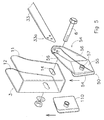
- Fig. 5 shows a variant of the strut connection of Figs. 3 and 4. This embodiment largely corresponds to the embodiment shown in Figs. 3 and 4. Corresponding parts are therefore indicated by the same reference numerals as those above.
- Fig. 5 shows a strut connecting piece 54 in the form of a U-shaped bracket 50, which is fitted on the side plate 11 of the bearing bracket.
- the U-shaped bracket 50 is comparable to the adjusting bracket 110 fitted on the other side plate 12 of the bearing bracket 3.
- One leg of the U-shaped bracket 50 forms a base plate 55, which is comparable to the base plate 35 in Fig. 4.
- the other leg 54 of the bracket 50 rests against the side plate 11 on the inside of the bearing bracket 3 and has the function of a wear plate.
- Holes 57 are provided in the legs 54, 55 of the bracket 50, through which holes the hinge bolt 6 is inserted during the fitting.
- two upright plates 56 extend from the base plate 55, which plates can be connected to the corresponding end 33a of the strut by means of welding or bolting, or in another way.
- Figs. 6 - 8 show a bearing bracket 3 with a strut connecting piece 64. Parts corresponding to the embodiments illustrated above are given the same reference numerals.
- the strut connecting piece 64 is in the form of a base plate 65 provided with a hole 67 through which the hinge bolt 6 is inserted during the fitting.
- An upright wall 66 is provided on the base plate 65.
- the wall 66 is of a substantially semi-circular shape and in the fitted state (Figs. 6 and 8) is directed with the hollow side facing downwards.
- a groove 69 is provided on the top side 68 of the wall 66.
- the end 33a of a strut element 33 can be laid in this groove 69 during the fitting, as shown in Fig. 8, after which the end 33a is welded down on the upright wall 64 along the groove 69 on the top side 68.
- the strut connecting piece 64 is preferably produced by casting.
- a separate strut connecting piece is present in each case. It must, however, be understood that this is not essential according to the invention.
- An embodiment, not shown, in which the end of the strut element 33 is designed in such a way that said end can be connected directly to the bearing bracket 3 also, for example, falls within the scope of protection of the invention.
Landscapes
- Engineering & Computer Science (AREA)
- Mechanical Engineering (AREA)
- Chemical & Material Sciences (AREA)
- Combustion & Propulsion (AREA)
- Transportation (AREA)
- Vehicle Body Suspensions (AREA)
- Devices For Conveying Motion By Means Of Endless Flexible Members (AREA)
- Centrifugal Separators (AREA)
Applications Claiming Priority (2)
| Application Number | Priority Date | Filing Date | Title |
|---|---|---|---|
| NL1023548 | 2003-05-27 | ||
| NL1023548A NL1023548C2 (nl) | 2003-05-27 | 2003-05-27 | Wielasophanging. |
Publications (2)
| Publication Number | Publication Date |
|---|---|
| EP1481824A1 true EP1481824A1 (fr) | 2004-12-01 |
| EP1481824B1 EP1481824B1 (fr) | 2006-07-19 |
Family
ID=33129163
Family Applications (1)
| Application Number | Title | Priority Date | Filing Date |
|---|---|---|---|
| EP04076462A Expired - Lifetime EP1481824B1 (fr) | 2003-05-27 | 2004-05-17 | Suspension d'essieu |
Country Status (5)
| Country | Link |
|---|---|
| EP (1) | EP1481824B1 (fr) |
| AT (1) | ATE333385T1 (fr) |
| DE (1) | DE602004001545T2 (fr) |
| ES (1) | ES2268571T3 (fr) |
| NL (1) | NL1023548C2 (fr) |
Cited By (10)
| Publication number | Priority date | Publication date | Assignee | Title |
|---|---|---|---|---|
| EP1777085A2 (fr) | 2005-10-21 | 2007-04-25 | BPW Bergische Achsen KG | Suspension d'essieu pour bras tirés portant un essieu |
| WO2008074480A1 (fr) * | 2006-12-20 | 2008-06-26 | Saf-Holland Gmbh | Ensemble de châssis pour un véhicule |
| NL1033534C2 (nl) * | 2007-03-12 | 2008-09-15 | Weweler Nv | Schoring voor wielasophanging. |
| NL1033820C2 (nl) * | 2007-05-08 | 2008-11-11 | Weweler Nv | Veerhand. |
| WO2011119020A1 (fr) | 2010-03-25 | 2011-09-29 | Weweler Nederland B.V. | Support de montage de bras oscillant |
| DE102008000936B4 (de) * | 2008-04-02 | 2014-04-10 | Zf Friedrichshafen Ag | Radaufhängung für ein Fahrzeug und Verbindungselement für eine solche Radaufhängung |
| CN110194039A (zh) * | 2019-06-27 | 2019-09-03 | 湖北中尔车轴有限公司 | 一种中置减震器空气悬架 |
| CN114945483A (zh) * | 2020-01-10 | 2022-08-26 | Vdl维维乐有限公司 | 底盘安装单元 |
| US20220305860A1 (en) * | 2021-03-26 | 2022-09-29 | Bombardier Recreational Products Inc. | Vehicle with wear plate |
| WO2024056748A1 (fr) | 2022-09-16 | 2024-03-21 | Vdl Weweler B.V. | Support de palier avec fixation d'entretoise et suspension d'essieu de roue comprenant un tel support de palier |
Citations (8)
| Publication number | Priority date | Publication date | Assignee | Title |
|---|---|---|---|---|
| DE2232935A1 (de) * | 1972-07-05 | 1974-01-24 | Wackenhut Ernst | Tragrahmen von lastfahrzeugen mit einzelfederaufhaengung |
| DE2618191A1 (de) * | 1976-04-26 | 1977-11-10 | Ernst Wackenhut | Tragrahmen von lastfahrzeugen, insbesondere anhaengern |
| EP0421556A1 (fr) | 1989-10-06 | 1991-04-10 | Weweler N.V. | Système à ressort pneumatique pour un véhicule |
| EP0890501A1 (fr) * | 1997-07-11 | 1999-01-13 | Weweler Nederland B.V. | Système à ressort pneumatique avec barres précontraintes |
| EP0995664A1 (fr) * | 1998-10-23 | 2000-04-26 | Weweler Nederland N.V. | Suspension d'un essieu pour un véhicule comportant un système à ressort pneumatique |
| EP1057716A1 (fr) * | 1999-06-04 | 2000-12-06 | BPW Bergische Achsen Kommanditgesellschaft | Construction d'essieu pour véhicules utilitaires, leurs remorques et semi-remorques |
| EP1284208A2 (fr) * | 2001-08-16 | 2003-02-19 | Weweler Nederland B.V. | Dispositif de fixation pour un support de palier d'un ensemble-essieu au châssis du véhicule |
| DE20300428U1 (de) * | 2003-01-13 | 2003-03-13 | Kögel Fahrzeugwerke Aktiengesellschaft, 89079 Ulm | Tragvorrichtung für ein Achsaggregat |
-
2003
- 2003-05-27 NL NL1023548A patent/NL1023548C2/nl not_active IP Right Cessation
-
2004
- 2004-05-17 AT AT04076462T patent/ATE333385T1/de not_active IP Right Cessation
- 2004-05-17 ES ES04076462T patent/ES2268571T3/es not_active Expired - Lifetime
- 2004-05-17 EP EP04076462A patent/EP1481824B1/fr not_active Expired - Lifetime
- 2004-05-17 DE DE602004001545T patent/DE602004001545T2/de not_active Expired - Lifetime
Patent Citations (8)
| Publication number | Priority date | Publication date | Assignee | Title |
|---|---|---|---|---|
| DE2232935A1 (de) * | 1972-07-05 | 1974-01-24 | Wackenhut Ernst | Tragrahmen von lastfahrzeugen mit einzelfederaufhaengung |
| DE2618191A1 (de) * | 1976-04-26 | 1977-11-10 | Ernst Wackenhut | Tragrahmen von lastfahrzeugen, insbesondere anhaengern |
| EP0421556A1 (fr) | 1989-10-06 | 1991-04-10 | Weweler N.V. | Système à ressort pneumatique pour un véhicule |
| EP0890501A1 (fr) * | 1997-07-11 | 1999-01-13 | Weweler Nederland B.V. | Système à ressort pneumatique avec barres précontraintes |
| EP0995664A1 (fr) * | 1998-10-23 | 2000-04-26 | Weweler Nederland N.V. | Suspension d'un essieu pour un véhicule comportant un système à ressort pneumatique |
| EP1057716A1 (fr) * | 1999-06-04 | 2000-12-06 | BPW Bergische Achsen Kommanditgesellschaft | Construction d'essieu pour véhicules utilitaires, leurs remorques et semi-remorques |
| EP1284208A2 (fr) * | 2001-08-16 | 2003-02-19 | Weweler Nederland B.V. | Dispositif de fixation pour un support de palier d'un ensemble-essieu au châssis du véhicule |
| DE20300428U1 (de) * | 2003-01-13 | 2003-03-13 | Kögel Fahrzeugwerke Aktiengesellschaft, 89079 Ulm | Tragvorrichtung für ein Achsaggregat |
Cited By (17)
| Publication number | Priority date | Publication date | Assignee | Title |
|---|---|---|---|---|
| EP1777085A2 (fr) | 2005-10-21 | 2007-04-25 | BPW Bergische Achsen KG | Suspension d'essieu pour bras tirés portant un essieu |
| EP1777085A3 (fr) * | 2005-10-21 | 2007-08-15 | BPW Bergische Achsen KG | Suspension d'essieu pour bras tirés portant un essieu |
| WO2008074480A1 (fr) * | 2006-12-20 | 2008-06-26 | Saf-Holland Gmbh | Ensemble de châssis pour un véhicule |
| US8276981B2 (en) | 2006-12-20 | 2012-10-02 | Saf-Holland Gmbh | Frame arrangement for a vehicle |
| EP1970225A1 (fr) * | 2007-03-12 | 2008-09-17 | Weweler Nederland N.V. | Agencement de renfort pour suspension d'essieu de roue |
| NL1033534C2 (nl) * | 2007-03-12 | 2008-09-15 | Weweler Nv | Schoring voor wielasophanging. |
| NL1033820C2 (nl) * | 2007-05-08 | 2008-11-11 | Weweler Nv | Veerhand. |
| EP2006129A1 (fr) * | 2007-05-08 | 2008-12-24 | Weweler Nederland N.V. | Main de ressort |
| DE102008000936B4 (de) * | 2008-04-02 | 2014-04-10 | Zf Friedrichshafen Ag | Radaufhängung für ein Fahrzeug und Verbindungselement für eine solche Radaufhängung |
| WO2011119020A1 (fr) | 2010-03-25 | 2011-09-29 | Weweler Nederland B.V. | Support de montage de bras oscillant |
| US8960694B2 (en) | 2010-03-25 | 2015-02-24 | Vdl Weweler B.V. | Trailing arm mounting bracket |
| CN110194039A (zh) * | 2019-06-27 | 2019-09-03 | 湖北中尔车轴有限公司 | 一种中置减震器空气悬架 |
| CN114945483A (zh) * | 2020-01-10 | 2022-08-26 | Vdl维维乐有限公司 | 底盘安装单元 |
| US20220305860A1 (en) * | 2021-03-26 | 2022-09-29 | Bombardier Recreational Products Inc. | Vehicle with wear plate |
| US11529834B2 (en) * | 2021-03-26 | 2022-12-20 | Bombardier Recreational Products Inc. | Vehicle with wear plate |
| WO2024056748A1 (fr) | 2022-09-16 | 2024-03-21 | Vdl Weweler B.V. | Support de palier avec fixation d'entretoise et suspension d'essieu de roue comprenant un tel support de palier |
| NL2033053B1 (en) | 2022-09-16 | 2024-03-25 | Vdl Weweler Bv | Bearing bracket with strut attachment and wheel axle suspension comprising such a bearing bracket |
Also Published As
| Publication number | Publication date |
|---|---|
| DE602004001545T2 (de) | 2007-07-05 |
| NL1023548C2 (nl) | 2004-11-30 |
| ES2268571T3 (es) | 2007-03-16 |
| EP1481824B1 (fr) | 2006-07-19 |
| DE602004001545D1 (de) | 2006-08-31 |
| ATE333385T1 (de) | 2006-08-15 |
Similar Documents
| Publication | Publication Date | Title |
|---|---|---|
| US5560651A (en) | Subframe and subframe assembly | |
| US20100007110A1 (en) | Linkage-type air suspension system | |
| CA2303042C (fr) | Systeme de suspension pneumatique pour vehicule | |
| US20080315571A1 (en) | Structure Supporting a Motor Vehicle Front End Assembly Comprising Coupling Means in the Form of a Hollow Body of a Mini-Cradle With Side Members, and Corresponding Vehicle | |
| EP2006129A1 (fr) | Main de ressort | |
| EP1481824B1 (fr) | Suspension d'essieu | |
| CA1226879A (fr) | Suspension independante de roue arriere | |
| US6733020B2 (en) | Suspension trailing arm | |
| US4714269A (en) | Wide base type suspension assembly with parallelogram torque beams and four air springs | |
| US20080143175A1 (en) | Beam axle system | |
| CA2691602C (fr) | Systeme de suspension pour un vehicule | |
| US11970042B2 (en) | Suspension assembly | |
| IE20070250A1 (en) | Independent suspension system | |
| EP0773119A1 (fr) | Améliorations concernant la suspension pneumatique d'un véhicule | |
| EP1086836A1 (fr) | Main de suspension pour la fixation d'un ensemble essieu au chassis de véhicule | |
| EP1284208B1 (fr) | Dispositif de fixation pour un support de palier d'un ensemble-essieu au châssis du véhicule | |
| US6659481B2 (en) | Attachment of a vehicle axle to an axle suspension | |
| JP2017190124A (ja) | リヤトレーリングアームの支持構造 | |
| US6302418B1 (en) | Modular suspension beam | |
| EP1459914B1 (fr) | Fixation d'un support de palier d'un ensemble-essieu au châssis d'un véhicule | |
| EP1380448A1 (fr) | Dispositif pour connecter un essieu au châssis d'un véhicule | |
| FR2702709A1 (fr) | Train arrière de véhicule automobile du type à bras tirés. | |
| KR100335198B1 (ko) | 자동차의 서스펜션 타워 지지대 | |
| AU2011218652B2 (en) | Integrated suspension and chassis assembly | |
| GB2349856A (en) | Vehicle air suspension |
Legal Events
| Date | Code | Title | Description |
|---|---|---|---|
| PUAI | Public reference made under article 153(3) epc to a published international application that has entered the european phase |
Free format text: ORIGINAL CODE: 0009012 |
|
| AK | Designated contracting states |
Kind code of ref document: A1 Designated state(s): AT BE BG CH CY CZ DE DK EE ES FI FR GB GR HU IE IT LI LU MC NL PL PT RO SE SI SK TR |
|
| AX | Request for extension of the european patent |
Extension state: AL HR LT LV MK |
|
| 17P | Request for examination filed |
Effective date: 20050210 |
|
| 17Q | First examination report despatched |
Effective date: 20050527 |
|
| AKX | Designation fees paid |
Designated state(s): AT BE BG CH CY CZ DE DK EE ES FI FR GB GR HU IE IT LI LU MC NL PL PT RO SE SI SK TR |
|
| GRAP | Despatch of communication of intention to grant a patent |
Free format text: ORIGINAL CODE: EPIDOSNIGR1 |
|
| GRAS | Grant fee paid |
Free format text: ORIGINAL CODE: EPIDOSNIGR3 |
|
| GRAA | (expected) grant |
Free format text: ORIGINAL CODE: 0009210 |
|
| AK | Designated contracting states |
Kind code of ref document: B1 Designated state(s): AT BE BG CH CY CZ DE DK EE ES FI FR GB GR HU IE IT LI LU MC NL PL PT RO SE SI SK TR |
|
| PG25 | Lapsed in a contracting state [announced via postgrant information from national office to epo] |
Ref country code: RO Free format text: LAPSE BECAUSE OF FAILURE TO SUBMIT A TRANSLATION OF THE DESCRIPTION OR TO PAY THE FEE WITHIN THE PRESCRIBED TIME-LIMIT Effective date: 20060719 Ref country code: CZ Free format text: LAPSE BECAUSE OF FAILURE TO SUBMIT A TRANSLATION OF THE DESCRIPTION OR TO PAY THE FEE WITHIN THE PRESCRIBED TIME-LIMIT Effective date: 20060719 Ref country code: AT Free format text: LAPSE BECAUSE OF FAILURE TO SUBMIT A TRANSLATION OF THE DESCRIPTION OR TO PAY THE FEE WITHIN THE PRESCRIBED TIME-LIMIT Effective date: 20060719 Ref country code: SK Free format text: LAPSE BECAUSE OF FAILURE TO SUBMIT A TRANSLATION OF THE DESCRIPTION OR TO PAY THE FEE WITHIN THE PRESCRIBED TIME-LIMIT Effective date: 20060719 Ref country code: PL Free format text: LAPSE BECAUSE OF FAILURE TO SUBMIT A TRANSLATION OF THE DESCRIPTION OR TO PAY THE FEE WITHIN THE PRESCRIBED TIME-LIMIT Effective date: 20060719 Ref country code: CH Free format text: LAPSE BECAUSE OF FAILURE TO SUBMIT A TRANSLATION OF THE DESCRIPTION OR TO PAY THE FEE WITHIN THE PRESCRIBED TIME-LIMIT Effective date: 20060719 Ref country code: LI Free format text: LAPSE BECAUSE OF FAILURE TO SUBMIT A TRANSLATION OF THE DESCRIPTION OR TO PAY THE FEE WITHIN THE PRESCRIBED TIME-LIMIT Effective date: 20060719 Ref country code: FI Free format text: LAPSE BECAUSE OF FAILURE TO SUBMIT A TRANSLATION OF THE DESCRIPTION OR TO PAY THE FEE WITHIN THE PRESCRIBED TIME-LIMIT Effective date: 20060719 Ref country code: SI Free format text: LAPSE BECAUSE OF FAILURE TO SUBMIT A TRANSLATION OF THE DESCRIPTION OR TO PAY THE FEE WITHIN THE PRESCRIBED TIME-LIMIT Effective date: 20060719 Ref country code: IT Free format text: LAPSE BECAUSE OF FAILURE TO SUBMIT A TRANSLATION OF THE DESCRIPTION OR TO PAY THE FEE WITHIN THE PRESCRIBED TIME-LIMIT;WARNING: LAPSES OF ITALIAN PATENTS WITH EFFECTIVE DATE BEFORE 2007 MAY HAVE OCCURRED AT ANY TIME BEFORE 2007. THE CORRECT EFFECTIVE DATE MAY BE DIFFERENT FROM THE ONE RECORDED. Effective date: 20060719 |
|
| REG | Reference to a national code |
Ref country code: GB Ref legal event code: FG4D |
|
| REG | Reference to a national code |
Ref country code: CH Ref legal event code: EP |
|
| REG | Reference to a national code |
Ref country code: IE Ref legal event code: FG4D |
|
| REF | Corresponds to: |
Ref document number: 602004001545 Country of ref document: DE Date of ref document: 20060831 Kind code of ref document: P |
|
| PG25 | Lapsed in a contracting state [announced via postgrant information from national office to epo] |
Ref country code: DK Free format text: LAPSE BECAUSE OF FAILURE TO SUBMIT A TRANSLATION OF THE DESCRIPTION OR TO PAY THE FEE WITHIN THE PRESCRIBED TIME-LIMIT Effective date: 20061019 Ref country code: SE Free format text: LAPSE BECAUSE OF FAILURE TO SUBMIT A TRANSLATION OF THE DESCRIPTION OR TO PAY THE FEE WITHIN THE PRESCRIBED TIME-LIMIT Effective date: 20061019 Ref country code: BG Free format text: LAPSE BECAUSE OF FAILURE TO SUBMIT A TRANSLATION OF THE DESCRIPTION OR TO PAY THE FEE WITHIN THE PRESCRIBED TIME-LIMIT Effective date: 20061019 |
|
| PG25 | Lapsed in a contracting state [announced via postgrant information from national office to epo] |
Ref country code: PT Free format text: LAPSE BECAUSE OF FAILURE TO SUBMIT A TRANSLATION OF THE DESCRIPTION OR TO PAY THE FEE WITHIN THE PRESCRIBED TIME-LIMIT Effective date: 20061219 |
|
| ET | Fr: translation filed | ||
| REG | Reference to a national code |
Ref country code: ES Ref legal event code: FG2A Ref document number: 2268571 Country of ref document: ES Kind code of ref document: T3 |
|
| PLBE | No opposition filed within time limit |
Free format text: ORIGINAL CODE: 0009261 |
|
| STAA | Information on the status of an ep patent application or granted ep patent |
Free format text: STATUS: NO OPPOSITION FILED WITHIN TIME LIMIT |
|
| 26N | No opposition filed |
Effective date: 20070420 |
|
| PG25 | Lapsed in a contracting state [announced via postgrant information from national office to epo] |
Ref country code: MC Free format text: LAPSE BECAUSE OF NON-PAYMENT OF DUE FEES Effective date: 20070531 |
|
| PG25 | Lapsed in a contracting state [announced via postgrant information from national office to epo] |
Ref country code: GR Free format text: LAPSE BECAUSE OF FAILURE TO SUBMIT A TRANSLATION OF THE DESCRIPTION OR TO PAY THE FEE WITHIN THE PRESCRIBED TIME-LIMIT Effective date: 20061020 |
|
| PG25 | Lapsed in a contracting state [announced via postgrant information from national office to epo] |
Ref country code: EE Free format text: LAPSE BECAUSE OF FAILURE TO SUBMIT A TRANSLATION OF THE DESCRIPTION OR TO PAY THE FEE WITHIN THE PRESCRIBED TIME-LIMIT Effective date: 20060719 |
|
| PGRI | Patent reinstated in contracting state [announced from national office to epo] |
Ref country code: IT Effective date: 20080801 |
|
| PG25 | Lapsed in a contracting state [announced via postgrant information from national office to epo] |
Ref country code: LU Free format text: LAPSE BECAUSE OF NON-PAYMENT OF DUE FEES Effective date: 20070517 Ref country code: CY Free format text: LAPSE BECAUSE OF FAILURE TO SUBMIT A TRANSLATION OF THE DESCRIPTION OR TO PAY THE FEE WITHIN THE PRESCRIBED TIME-LIMIT Effective date: 20060719 |
|
| PG25 | Lapsed in a contracting state [announced via postgrant information from national office to epo] |
Ref country code: TR Free format text: LAPSE BECAUSE OF FAILURE TO SUBMIT A TRANSLATION OF THE DESCRIPTION OR TO PAY THE FEE WITHIN THE PRESCRIBED TIME-LIMIT Effective date: 20060719 Ref country code: HU Free format text: LAPSE BECAUSE OF FAILURE TO SUBMIT A TRANSLATION OF THE DESCRIPTION OR TO PAY THE FEE WITHIN THE PRESCRIBED TIME-LIMIT Effective date: 20070120 |
|
| PGFP | Annual fee paid to national office [announced via postgrant information from national office to epo] |
Ref country code: IE Payment date: 20110406 Year of fee payment: 8 |
|
| PGFP | Annual fee paid to national office [announced via postgrant information from national office to epo] |
Ref country code: BE Payment date: 20110530 Year of fee payment: 8 Ref country code: NL Payment date: 20110608 Year of fee payment: 8 |
|
| BERE | Be: lapsed |
Owner name: *WEWELER NEDERLAND B.V. Effective date: 20120531 |
|
| REG | Reference to a national code |
Ref country code: NL Ref legal event code: V1 Effective date: 20121201 |
|
| REG | Reference to a national code |
Ref country code: IE Ref legal event code: MM4A |
|
| PG25 | Lapsed in a contracting state [announced via postgrant information from national office to epo] |
Ref country code: BE Free format text: LAPSE BECAUSE OF NON-PAYMENT OF DUE FEES Effective date: 20120531 |
|
| PG25 | Lapsed in a contracting state [announced via postgrant information from national office to epo] |
Ref country code: NL Free format text: LAPSE BECAUSE OF NON-PAYMENT OF DUE FEES Effective date: 20121201 |
|
| PG25 | Lapsed in a contracting state [announced via postgrant information from national office to epo] |
Ref country code: IE Free format text: LAPSE BECAUSE OF NON-PAYMENT OF DUE FEES Effective date: 20120517 |
|
| REG | Reference to a national code |
Ref country code: FR Ref legal event code: PLFP Year of fee payment: 13 |
|
| REG | Reference to a national code |
Ref country code: FR Ref legal event code: PLFP Year of fee payment: 14 |
|
| REG | Reference to a national code |
Ref country code: FR Ref legal event code: PLFP Year of fee payment: 15 |
|
| PGFP | Annual fee paid to national office [announced via postgrant information from national office to epo] |
Ref country code: IT Payment date: 20180529 Year of fee payment: 15 Ref country code: FR Payment date: 20180523 Year of fee payment: 15 |
|
| GBPC | Gb: european patent ceased through non-payment of renewal fee |
Effective date: 20190517 |
|
| PG25 | Lapsed in a contracting state [announced via postgrant information from national office to epo] |
Ref country code: GB Free format text: LAPSE BECAUSE OF NON-PAYMENT OF DUE FEES Effective date: 20190517 Ref country code: IT Free format text: LAPSE BECAUSE OF FAILURE TO SUBMIT A TRANSLATION OF THE DESCRIPTION OR TO PAY THE FEE WITHIN THE PRESCRIBED TIME-LIMIT Effective date: 20190517 |
|
| PG25 | Lapsed in a contracting state [announced via postgrant information from national office to epo] |
Ref country code: FR Free format text: LAPSE BECAUSE OF NON-PAYMENT OF DUE FEES Effective date: 20190531 |
|
| PGFP | Annual fee paid to national office [announced via postgrant information from national office to epo] |
Ref country code: DE Payment date: 20230519 Year of fee payment: 20 |
|
| PGFP | Annual fee paid to national office [announced via postgrant information from national office to epo] |
Ref country code: ES Payment date: 20230719 Year of fee payment: 20 |
|
| REG | Reference to a national code |
Ref country code: DE Ref legal event code: R071 Ref document number: 602004001545 Country of ref document: DE |
|
| REG | Reference to a national code |
Ref country code: ES Ref legal event code: FD2A Effective date: 20240524 |
|
| PG25 | Lapsed in a contracting state [announced via postgrant information from national office to epo] |
Ref country code: ES Free format text: LAPSE BECAUSE OF EXPIRATION OF PROTECTION Effective date: 20240518 |
|
| PG25 | Lapsed in a contracting state [announced via postgrant information from national office to epo] |
Ref country code: ES Free format text: LAPSE BECAUSE OF EXPIRATION OF PROTECTION Effective date: 20240518 |