EP1380448A1 - Dispositif pour connecter un essieu au châssis d'un véhicule - Google Patents
Dispositif pour connecter un essieu au châssis d'un véhicule Download PDFInfo
- Publication number
- EP1380448A1 EP1380448A1 EP03077187A EP03077187A EP1380448A1 EP 1380448 A1 EP1380448 A1 EP 1380448A1 EP 03077187 A EP03077187 A EP 03077187A EP 03077187 A EP03077187 A EP 03077187A EP 1380448 A1 EP1380448 A1 EP 1380448A1
- Authority
- EP
- European Patent Office
- Prior art keywords
- connecting bar
- strut
- secured
- recess
- chassis
- Prior art date
- Legal status (The legal status is an assumption and is not a legal conclusion. Google has not performed a legal analysis and makes no representation as to the accuracy of the status listed.)
- Withdrawn
Links
Images

Classifications
-
- B—PERFORMING OPERATIONS; TRANSPORTING
- B60—VEHICLES IN GENERAL
- B60G—VEHICLE SUSPENSION ARRANGEMENTS
- B60G9/00—Resilient suspensions of a rigid axle or axle housing for two or more wheels
- B60G9/003—Resilient suspensions of a rigid axle or axle housing for two or more wheels the axle being rigidly connected to a trailing guiding device
-
- B—PERFORMING OPERATIONS; TRANSPORTING
- B60—VEHICLES IN GENERAL
- B60G—VEHICLE SUSPENSION ARRANGEMENTS
- B60G7/00—Pivoted suspension arms; Accessories thereof
- B60G7/02—Attaching arms to sprung part of vehicle
-
- B—PERFORMING OPERATIONS; TRANSPORTING
- B60—VEHICLES IN GENERAL
- B60G—VEHICLE SUSPENSION ARRANGEMENTS
- B60G2200/00—Indexing codes relating to suspension types
- B60G2200/30—Rigid axle suspensions
- B60G2200/31—Rigid axle suspensions with two trailing arms rigidly connected to the axle
-
- B—PERFORMING OPERATIONS; TRANSPORTING
- B60—VEHICLES IN GENERAL
- B60G—VEHICLE SUSPENSION ARRANGEMENTS
- B60G2204/00—Indexing codes related to suspensions per se or to auxiliary parts
- B60G2204/10—Mounting of suspension elements
- B60G2204/14—Mounting of suspension arms
-
- B—PERFORMING OPERATIONS; TRANSPORTING
- B60—VEHICLES IN GENERAL
- B60G—VEHICLE SUSPENSION ARRANGEMENTS
- B60G2204/00—Indexing codes related to suspensions per se or to auxiliary parts
- B60G2204/10—Mounting of suspension elements
- B60G2204/14—Mounting of suspension arms
- B60G2204/143—Mounting of suspension arms on the vehicle body or chassis
-
- B—PERFORMING OPERATIONS; TRANSPORTING
- B60—VEHICLES IN GENERAL
- B60G—VEHICLE SUSPENSION ARRANGEMENTS
- B60G2204/00—Indexing codes related to suspensions per se or to auxiliary parts
- B60G2204/10—Mounting of suspension elements
- B60G2204/15—Mounting of subframes
Definitions
- the invention relates to a device for securing a wheel axle to the chassis of a vehicle, comprising two bearing brackets secured to the chassis on either side of the vehicle, two carrier arms, which are each pivotably secured to an associated bearing bracket and to which the wheel axle is secured, a connecting bar which extends between the two bearing brackets and the ends of which are secured to the bearing brackets, and two struts, each of which are connected at one end to the connecting bar in the central region of the connecting bar by means of a threaded connection comprising a single threaded bolt and, from there, extend obliquely upwards in order to be secured to the chassis at the other end.
- a device of this type is known, for example, from EP-A-0421556.
- the struts are connected to the connecting bar in the centre of the connecting bar by means of a common threaded bolt.
- This design has the drawback that the maximum force which can be transmitted by the connection between the connecting bar and a strut is limited. This is because this force is determined by the sum of the maximum shear force of the threaded bolt and the maximum frictional force between the connecting bar and the strut.
- This problem could be resolved by using a plurality of threaded bolts in a connection between the connecting bar and a strut. However, this has the drawback that the angle between the strut and the connecting bar is then fixed.
- connecting bar and struts of this type which has been prepared in a factory cannot be used for vehicles with a varying vertical distance between connecting bar and chassis and differing track widths. It is disadvantageous to drill holes into the connecting bar during assembly to the vehicle, since in most cases the connecting bar is provided with a corrosion-resistant layer. This layer would then be damaged.
- the measure according to the invention ensures that the connection between the connecting bar and a strut is at least partially positively locking, with the result that a considerably greater force can be transmitted. Consequently, it is possible to make do with a single threaded bolt, so that the angle between the connecting bar and a strut can be adjusted.
- the depth of the recess prefferably be greater than the height of the elevation. This enables a strut to be clamped with prestress against the connecting bar by the threaded bolt.
- the invention also relates to a combination of a connecting bar and two struts which is intended for the device according to the invention.
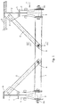
- Figs 1 and 2 illustrate a specific embodiment of the device for securing a wheel axle to the chassis of a vehicle.
- the chassis of the vehicle comprises two chassis beams 1 and 2 which are located on either side of the vehicle and in this case are I-shaped in cross section.
- the chassis beams 1, 2 inter alia support a loading platform 3 of the vehicle.
- a bearing bracket 6, 7 is secured to the bottom flange 4, 5 of each chassis beam 1, 2 by means of a welded joint or a threaded bolt connection.
- a carrier arm 8, 9 is secured to the underside of each bearing bracket 6, 7 in such a manner that it can pivot about a pivot pin 8a, 9a. When they are fitted to the vehicle, the carrier arms extend in the longitudinal direction of the vehicle.
- the wheel axle (not shown) is secured to the two carrier arms 8, 9, extending transversely with respect to the carrier arms.
- a shock absorber 10 will be mounted between a carrier arm 8, 9 and an associated bearing bracket.
- the connecting bar 11 is responsible for increasing the rigidity of the structure.
- the rigidity of the structure is further increased by two struts 12, 13 which are arranged between the connecting bar 11 and the chassis beams 1, 2.
- One end of the struts 12, 13 is connected to the connecting bar in the central region of the connecting bar 11 by means of a single threaded bolt 14, 15.
- the struts 12, 13 are secured by means of bolts or by welding to a mounting plate 16, 17 which is welded to the corresponding chassis beam 1, 2.
- the connecting bar 11 and/or the strut 12, 13 is provided with a recess 18, 18', and furthermore there is an element 19, 20, which is coupled to the strut 12, 13 and/or the connecting bar 11 at least in the transverse direction of the threaded bolt 15 and which with respect to the strut 12, 13 and/or the connecting bar 11 forms an elevation which latches into the recess 18, 18'.
- the strut 13 is provided with an elevation 19 which latches into the recess 18.
- the struts 12 and 13 may be provided with a recess and the connecting bar 11 to be provided with elevations.
- the recesses 18 and elevations 19 in the connecting bar 11 and the struts 12 and 13 prefferably be formed by a plastically deformed (pressed) section of the connecting bar 11 or struts 12 and 13, as in the embodiment shown in Fig. 3. If appropriate, the elevation could also be applied by welding on a plug.
- both the connecting bar 11 and the strut 13 are provided with a recess 18 and 18', respectively, and the element which is coupled to the strut 13 and the connecting bar 11 is formed by a ring 20 which latches both into the recess 18 in the connecting bar 11 and into the recess 18' in the strut 13.
- the ring 20 is preferably bevelled at the outer edge on both sides, and the shape of the ring 20 and the shape of the recesses 18, 18' are matched to one another. The result is a very strong connection.
- connection between the connecting bar 11 and a strut 12, 13 at least partially positively locking, with the result that a relatively high force can be transmitted. Consequently, it is possible to make do with a single threaded bolt 14, 15, so that the angle between the connecting bar 11 and a strut 12, 13 can still be adjusted and can be matched to the height of the bearing brackets 6, 7, the height of the chassis beams 1, 2 and/or the track width of the vehicle, i.e. the distance between the chassis bars 1, 2.
- the depth of the recess 18 is preferably greater than the height of the elevation, so that there is a small space between the recess and the elevation. As a result, a strut 12, 13 can be clamped against the connecting bar 11 with prestress by the threaded bolt 14, 15, which is advantageous for the purpose of transmitting forces.
Landscapes
- Engineering & Computer Science (AREA)
- Mechanical Engineering (AREA)
- Vehicle Body Suspensions (AREA)
Applications Claiming Priority (2)
| Application Number | Priority Date | Filing Date | Title |
|---|---|---|---|
| NL1021052A NL1021052C2 (nl) | 2002-07-11 | 2002-07-11 | Inrichting voor het bevestigen van een wielas aan het chassis van een voertuig. |
| NL1021052 | 2002-07-11 |
Publications (1)
| Publication Number | Publication Date |
|---|---|
| EP1380448A1 true EP1380448A1 (fr) | 2004-01-14 |
Family
ID=29728920
Family Applications (1)
| Application Number | Title | Priority Date | Filing Date |
|---|---|---|---|
| EP03077187A Withdrawn EP1380448A1 (fr) | 2002-07-11 | 2003-07-10 | Dispositif pour connecter un essieu au châssis d'un véhicule |
Country Status (2)
| Country | Link |
|---|---|
| EP (1) | EP1380448A1 (fr) |
| NL (1) | NL1021052C2 (fr) |
Cited By (1)
| Publication number | Priority date | Publication date | Assignee | Title |
|---|---|---|---|---|
| WO2008074480A1 (fr) * | 2006-12-20 | 2008-06-26 | Saf-Holland Gmbh | Ensemble de châssis pour un véhicule |
Citations (8)
| Publication number | Priority date | Publication date | Assignee | Title |
|---|---|---|---|---|
| DE2313928A1 (de) * | 1973-03-21 | 1974-09-26 | Messerschmitt Boelkow Blohm | Zug- und druckverbindungselement |
| DE2607154A1 (de) * | 1976-02-21 | 1977-09-01 | Kober Manpar Ag | Flanschverbindung fuer rahmen o.dgl. |
| GB2004819A (en) * | 1977-09-27 | 1979-04-11 | Korber Kg Alois | Connection between a vehicle axle and a longitudinal member of a vehicle chassis |
| GB1562883A (en) * | 1977-01-20 | 1980-03-19 | Kober Kg A | Chassis for a trailer |
| FR2474988A1 (fr) * | 1980-02-01 | 1981-08-07 | Ftf | Chassis modulaire, notamment pour les caravanes ou autres remorques routieres |
| GB2109501A (en) * | 1981-09-24 | 1983-06-02 | Ftf Achsen Gmbh | Sheet metal connectors |
| EP0421556A1 (fr) | 1989-10-06 | 1991-04-10 | Weweler N.V. | Système à ressort pneumatique pour un véhicule |
| EP0890501A1 (fr) * | 1997-07-11 | 1999-01-13 | Weweler Nederland B.V. | Système à ressort pneumatique avec barres précontraintes |
-
2002
- 2002-07-11 NL NL1021052A patent/NL1021052C2/nl not_active IP Right Cessation
-
2003
- 2003-07-10 EP EP03077187A patent/EP1380448A1/fr not_active Withdrawn
Patent Citations (8)
| Publication number | Priority date | Publication date | Assignee | Title |
|---|---|---|---|---|
| DE2313928A1 (de) * | 1973-03-21 | 1974-09-26 | Messerschmitt Boelkow Blohm | Zug- und druckverbindungselement |
| DE2607154A1 (de) * | 1976-02-21 | 1977-09-01 | Kober Manpar Ag | Flanschverbindung fuer rahmen o.dgl. |
| GB1562883A (en) * | 1977-01-20 | 1980-03-19 | Kober Kg A | Chassis for a trailer |
| GB2004819A (en) * | 1977-09-27 | 1979-04-11 | Korber Kg Alois | Connection between a vehicle axle and a longitudinal member of a vehicle chassis |
| FR2474988A1 (fr) * | 1980-02-01 | 1981-08-07 | Ftf | Chassis modulaire, notamment pour les caravanes ou autres remorques routieres |
| GB2109501A (en) * | 1981-09-24 | 1983-06-02 | Ftf Achsen Gmbh | Sheet metal connectors |
| EP0421556A1 (fr) | 1989-10-06 | 1991-04-10 | Weweler N.V. | Système à ressort pneumatique pour un véhicule |
| EP0890501A1 (fr) * | 1997-07-11 | 1999-01-13 | Weweler Nederland B.V. | Système à ressort pneumatique avec barres précontraintes |
Cited By (2)
| Publication number | Priority date | Publication date | Assignee | Title |
|---|---|---|---|---|
| WO2008074480A1 (fr) * | 2006-12-20 | 2008-06-26 | Saf-Holland Gmbh | Ensemble de châssis pour un véhicule |
| US8276981B2 (en) | 2006-12-20 | 2012-10-02 | Saf-Holland Gmbh | Frame arrangement for a vehicle |
Also Published As
| Publication number | Publication date |
|---|---|
| NL1021052C2 (nl) | 2004-01-13 |
Similar Documents
| Publication | Publication Date | Title |
|---|---|---|
| US8371596B2 (en) | Suspension system for heavy and vocational vehicles | |
| US7328908B2 (en) | Steer axle and method of making the same | |
| CN100355613C (zh) | 车辆用悬架支撑部结构 | |
| AU9672798A (en) | Trailing arm axle/suspension system | |
| EP2006129A1 (fr) | Main de ressort | |
| CN110325382B (zh) | 车辆悬架布置 | |
| US6702309B2 (en) | Rear suspension for vehicles | |
| US4714269A (en) | Wide base type suspension assembly with parallelogram torque beams and four air springs | |
| US7540514B2 (en) | Vehicle suspensions | |
| EP1481824A1 (fr) | Suspension d'essieu | |
| EP1380448A1 (fr) | Dispositif pour connecter un essieu au châssis d'un véhicule | |
| EP2429839B1 (fr) | Support de montage d'un bras oscillant | |
| CN106427520B (zh) | 汽车及其发动机支承结构 | |
| EP1284208B1 (fr) | Dispositif de fixation pour un support de palier d'un ensemble-essieu au châssis du véhicule | |
| US6626454B1 (en) | Trailer suspension | |
| US6659481B2 (en) | Attachment of a vehicle axle to an axle suspension | |
| EP1086836A1 (fr) | Main de suspension pour la fixation d'un ensemble essieu au chassis de véhicule | |
| AU653876B2 (en) | Shuttlecar equaliser | |
| KR20200086568A (ko) | 트레일링암 마운팅브래킷 | |
| EP4087742B1 (fr) | Unité de montage de châssis | |
| US5791743A (en) | Beam to axle weld stiffener | |
| EP1459914A1 (fr) | Fixation d'un support de palier d'un ensemble-essieu au châssis d'un véhicule | |
| CN219487576U (zh) | 前轮罩总成及车辆 | |
| CN106585543A (zh) | 自卸车车身侧防护装置 | |
| KR200206928Y1 (ko) | 자동차 현가장치의 로워 컨트롤 아암 |
Legal Events
| Date | Code | Title | Description |
|---|---|---|---|
| PUAI | Public reference made under article 153(3) epc to a published international application that has entered the european phase |
Free format text: ORIGINAL CODE: 0009012 |
|
| AK | Designated contracting states |
Kind code of ref document: A1 Designated state(s): AT BE BG CH CY CZ DE DK EE ES FI FR GB GR HU IE IT LI LU MC NL PT RO SE SI SK TR |
|
| AX | Request for extension of the european patent |
Extension state: AL LT LV MK |
|
| AKX | Designation fees paid | ||
| REG | Reference to a national code |
Ref country code: DE Ref legal event code: 8566 |
|
| STAA | Information on the status of an ep patent application or granted ep patent |
Free format text: STATUS: THE APPLICATION IS DEEMED TO BE WITHDRAWN |
|
| 18D | Application deemed to be withdrawn |
Effective date: 20040715 |