EP1481744A1 - Verfahren und Vorrichtung zur Herstellung eines Formteiles, sowie Formteil, insbesondere ein Behälterboden - Google Patents
Verfahren und Vorrichtung zur Herstellung eines Formteiles, sowie Formteil, insbesondere ein Behälterboden Download PDFInfo
- Publication number
- EP1481744A1 EP1481744A1 EP04003037A EP04003037A EP1481744A1 EP 1481744 A1 EP1481744 A1 EP 1481744A1 EP 04003037 A EP04003037 A EP 04003037A EP 04003037 A EP04003037 A EP 04003037A EP 1481744 A1 EP1481744 A1 EP 1481744A1
- Authority
- EP
- European Patent Office
- Prior art keywords
- brim
- heat supply
- calotte
- radius
- transition region
- Prior art date
- Legal status (The legal status is an assumption and is not a legal conclusion. Google has not performed a legal analysis and makes no representation as to the accuracy of the status listed.)
- Granted
Links
- 238000000034 method Methods 0.000 title claims abstract description 42
- 238000003825 pressing Methods 0.000 claims abstract description 23
- 238000010438 heat treatment Methods 0.000 claims abstract description 12
- 229910052751 metal Inorganic materials 0.000 claims abstract description 12
- 239000002184 metal Substances 0.000 claims abstract description 12
- 238000009987 spinning Methods 0.000 claims abstract description 10
- 229910052782 aluminium Inorganic materials 0.000 claims abstract description 6
- XAGFODPZIPBFFR-UHFFFAOYSA-N aluminium Chemical compound [Al] XAGFODPZIPBFFR-UHFFFAOYSA-N 0.000 claims abstract description 6
- 230000007704 transition Effects 0.000 claims description 42
- 238000004519 manufacturing process Methods 0.000 claims description 8
- 239000000463 material Substances 0.000 claims description 7
- 238000002788 crimping Methods 0.000 claims description 6
- 235000014443 Pyrus communis Nutrition 0.000 claims 1
- 239000004411 aluminium Substances 0.000 abstract 1
- 238000007493 shaping process Methods 0.000 description 12
- 239000011324 bead Substances 0.000 description 6
- 238000000137 annealing Methods 0.000 description 4
- 238000000465 moulding Methods 0.000 description 4
- 230000015572 biosynthetic process Effects 0.000 description 3
- 230000003247 decreasing effect Effects 0.000 description 2
- 229910000838 Al alloy Inorganic materials 0.000 description 1
- 241001156002 Anthonomus pomorum Species 0.000 description 1
- 229910045601 alloy Inorganic materials 0.000 description 1
- 239000000956 alloy Substances 0.000 description 1
- 230000002146 bilateral effect Effects 0.000 description 1
- 230000005489 elastic deformation Effects 0.000 description 1
- 239000010410 layer Substances 0.000 description 1
- 239000002344 surface layer Substances 0.000 description 1
Images



Classifications
-
- B—PERFORMING OPERATIONS; TRANSPORTING
- B21—MECHANICAL METAL-WORKING WITHOUT ESSENTIALLY REMOVING MATERIAL; PUNCHING METAL
- B21D—WORKING OR PROCESSING OF SHEET METAL OR METAL TUBES, RODS OR PROFILES WITHOUT ESSENTIALLY REMOVING MATERIAL; PUNCHING METAL
- B21D22/00—Shaping without cutting, by stamping, spinning, or deep-drawing
- B21D22/14—Spinning
- B21D22/18—Spinning using tools guided to produce the required profile
- B21D22/185—Spinning using tools guided to produce the required profile making domed objects
Definitions
- the invention relates to a method and a device for metal pressing Blanks, in particular made of aluminum, to form a curved molding, in particular a container bottom, with the in the preamble of claims 1, 13 and 22 features mentioned.
- a blank is available as a sheet blank or preform set in rotation and by an advanced and advanced pressing tool brought into the desired, rotationally symmetrical molded part.
- An overview about known spinning processes is in "Blech-Rohr-Profiles" 28 (1981) 11, Pages 514 - 517 removable.
- the blank is used in the known pressing processes centered in a pressure chuck, the outer contour of the inner contour of the desired molded part.
- the press tool in the form of a Press roller follows the outer contour of the desired molded part, see above that the blank is formed between the spinning roller and the spinning chuck can.
- the spinning roller is either over copy templates or motion-controlled via an NC control.
- Moldings that are particularly common in practice are container bottoms from Pressure vessels with a cylindrical jacket. According to the degree of curvature of the calotte A distinction is made between container bases, dished ends, arched bases, Hemispherical floors as well as plate floors and flat floors. With decreasing curvature or with increasing radius of curvature, the simplifies Manufacture so that especially bobbin and arched floors a one-piece blank.
- DE 100 47 491 A1 discloses a method for reshaping structures made of aluminum alloys, which reshapes a component to be reshaped by elastic shaping into a predetermined contour under the influence of external force and heating the elastically shaped component to a temperature higher than that for creep shaping and stress relaxation of the alloy required temperature, so that the component is deformed while maintaining the contour.
- This method is exemplary of methods in which forces first act in a first shaping step in order to achieve a predetermined contour of a component and in a second step a heat treatment is carried out, by means of which the stresses which have arisen are subsequently eliminated.
- This two-stage implementation of the shaping process is very complex and requires heating of the entire component in order to remove the existing stresses.
- the invention is therefore based on the object of a method and a device to propose which cost-effective a precise forming of Molded parts, in particular of container bottoms, allowed, in particular in the areas where the forming process can cause high stresses Tensions can be avoided during the forming process or occur only to a very small extent.
- a spherical cap with a definable radius of curvature rotates is held down and at the same time heat is supplied in one, by one Predeterminable diameter of the spherical cap determines a transition area Brim is formed with a predetermined radius, the formation of Tensions in the transition area between the calotte and the brim from the start avoided, so that subsequent annealing is generally dispensed with can.
- the dome is only in the transition area to reduce the stresses to warm up, so that heating up of the entire component can be dispensed with.
- a rotating device on which the rotating calotte by at least one stationary heat supply device and one stationary one Forming tool at least in the transition area of the predetermined Diameter can be heated and a brim can be shaped to a predefinable radius a device is formed which advantageously allows the calotte exactly in the specified transition area by means of the heat supply device to form and by an arranged stationary forming tool shape the brim tension-free to a predefinable radius.
- the at least one heat supply device becomes in the transition area positioned in front of the forming tool in the direction of rotation.
- the at least one heat supply device becomes in the transition area positioned in front of the forming tool in the direction of rotation.
- several heat supply devices at the transition area arranged between the calotte and brim, which in a first Version opposite or in a second version be arranged symmetrically on the calotte.
- An arrangement of the heat supply device from the outside is preferred the calotte, with an arrangement from the inside respectively from the outside and inside and thus a one-sided respectively bilateral effect on the transition area can be achieved.
- the heat supply device Transition area heated evenly, with a desired forming temperature is selectable for the molded part.
- the heating of the molded part at the given Temperature leads to a plastic under stress relaxation Forming the calotte in the transition area while shaping the brim.
- 120 ° C. can be specified as the preferred temperature, here depending on the material other temperatures can also be specified.
- the predeterminable temperature in the transition area between the calotte and the brim by controlling the heat supply device and / or spacing of the heat supply device from the surface the calotte or the brim is adjusted. Eventually by controlling and / or spacing the heat supply device Effective area of the heat supply device depending on the desired the area of the transition area to be heated.
- the device according to the invention for carrying out the method comprises a pressing tool for metal pressing a blank, a clamping device for Clamping the blank and a rotating device on which the rotating Calotte by at least one stationary heat supply device and one stationary forming tool is formable.
- the rotation device has a rotation table with a support element and a hold-down.
- the hold-down preferably engages in the center on an inside of the molded part, in particular the calotte.
- the pressing tool and the stationary forming tool can be carried out in a common device or in separate devices.
- the pressing tool engages on the inside of the calotte, the stationary one Forming tool in a preferred embodiment of the invention, a bead is, which is also on the inside of the calotte and a crimping roller, which on attacks an outside of the calotte.
- the calotte on the predeterminable diameter and trained transition area by the heat supply device such It is possible to heat the brim to a predeterminable radius by means of plastic Material forming can be trained.
- the heat supply device has a stand element, a base element, a first and a second fastening element and a media connection and a burner.
- the first and second fasteners are used to set an angle and a distance of the Brenners opposite the calotte or for adjusting a height of the burner towards the calotte.
- the burner is through the first and / or second
- the device can be arranged so that the burner flame is at right angles to the transition area hits, with the burner at all times before and during the procedure readjustable, i.e. also at different angles to the surface to be deformed is adjustable in the transition area.
- the process in which the forming of the molded part in the transition area and its heating can be carried out at the same time becomes more advantageous Way at the temperature suitable for the material to be formed, the is preferably only about 120 ° C and in any case below an annealing temperature lies, the formation of tensions in the strongly reshaped transition area avoided from the outset between the calotte and the brim.
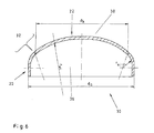
- FIG. 6 shows schematically a container base 30, in particular a basket arch base.
- the container bottom 30 has a cap 22 and a brim 20.
- the calotte 22 has a radius of curvature r wi and the brim 20 has a radius r ki .
- the cap 22 itself is determined by the diameter d k and the brim 20 and the cap 22 by a nominal diameter d a .
- FIG. 6 shows a transition area 32 between brim 20 and cap 22.
- FIG. 1 shows a device 10 according to the invention, which holds the container bottom 30, in particular the spherical cap 22, in a clamping means 12, so that a pressing tool 14 is used to deform the blank to form the spherical cap 22.
- the clamping means 12 can be designed in different ways, it is essential that the clamping means 12 hold the spherical cap 22 rotating in a clamped position.
- the pressing tool 14 permits, in addition to the fixing of the spherical cap 22, rotation within the tools of the clamping means 12.
- the blank, in particular the spherical cap 22, is given the radius of curvature r wi by the shaping by means of the pressing tool 14.
- FIG 2 shows essentially a heat supply device 18 for training the brim 20 on the - as described in Figure 1 - shaped dome 22.
- the heat supply device 18 has a stand element 18A, a base element 18B, a media port 18E and a burner 18F on the adjustable in length by a first fastening element 18C and by a second fastener 18D adjustable in height and angle is arranged.
- the heat supply device 18, in particular the Burner 18F acts on the transition area 32 between the brim 20 and the calotte 22, in the exemplary embodiment from an outer side 38 of the container bottom 30th
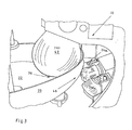
- Figure 3 shows the device 10, in particular a forming tool 16, which is designed in the form of a bead 42 and from an inside 36 acts on the container bottom 30.
- the forming tool 16 forms the bead 42 opposite at least one crimping roller 24 from the bottom of the container 30 leads and holds in the area of the brim 20 to be trained.
- Figure 3 shows in addition to the flanging roller 24 two pressure rollers 24a, which stabilize the workpiece.
- the rotary table 40 is shown in FIG. 4 and essentially has one Support element 28 and a hold-down 26.
- the container bottom 30 is in the forming tool 16 rotated on the rotary table 40 and in Area of the bead 42 and the rollers 24 (not visible in Figure 4) formed.
- the brim 20 is formed with a predetermined radius r ki , while at the same time supplying heat in the transition region 32, starting from the predetermined diameter d k of the calotte 22.
- FIG. 4 shows this process of shaping the brim 20, with the heat supply devices 18 symmetrical with respect to the bead 42 and the bead rolls 24 are arranged.
- the heat supply devices 18 are arranged so that heat supply via the burner 18F is precisely in the transition region 32 between brim 20 and calotte 22 is reached.
- acts the heat supply device 18 from the outside 38 on the calotte 22 or the brim 20 in the transition area 32 also a supply of heat from the inside 36 or inner side 36 and outer side 38 can be carried out on both sides.
- stress relaxation is achieved at the same time.
- a control unit 48 with a control system for controlling the entire device 10, consisting of the pressing tool 14 and the forming tool 16.
- the control device and the control system 48 can also be used for control purposes the heat supply device 18 (not shown) can be used.
- Another option is to set the temperature only over time.
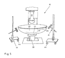
- FIG. 5 shows the container base 30 produced, in particular an arched base, after returning the hold-down 26 of the forming tool 16.
- the forming tools 18 are also for removing the container bottom 30 can be moved easily via rollers 44, as shown in FIG. 5.
- the method and the device are particularly suitable for the production of bobbin-case bases and wicker-arch bases made of aluminum.
- the production of larger container bottoms usually leads to a decrease in the radii r ki of the brim 20 so that the calotte 22 and brim 20 are produced separately and are later joined together again, in particular by welded connections. This procedure is carried out in particular because tensions can usually be insufficiently avoided in a one-piece production.
- the new method and the associated device now allow container bottoms 30 to be produced in one piece with the supply of heat in the transition region 32 and to achieve stress relaxation, in particular also when a decreasing radius r ki is to be formed into a particularly strongly shaped brim 22.
Landscapes
- Engineering & Computer Science (AREA)
- Mechanical Engineering (AREA)
- Shaping Metal By Deep-Drawing, Or The Like (AREA)
- Processing And Handling Of Plastics And Other Materials For Molding In General (AREA)
- Encapsulation Of And Coatings For Semiconductor Or Solid State Devices (AREA)
Abstract
Description
Diese zweistufige Durchführung des Formgebungsverfahrens ist sehr aufwendig und erfordert die Erwärmung des gesamten Bauteils zur Beseitigung der vorhandenen Spannungen.
- Figur 1
- eine Vorrichtung zum Metalldrücken als Drückwerkzeug eines Formteiles mit zugehörigem Einspannmittel;
- Figur 2
- das Formteil und eine Wärmezuführungseinrichtung;
- Figur 3
- das Formteil und eine Vorrichtung zum Umformen als ein Umformwerkzeug;
- Figur 4
- das Umformwerkzeug mit angeordneten Wärmezuführungseinrichtungen während der Umformung;
- Figur 5
- das Umformwerkzeug mit Wärmezuführungseinrichtung nach der Umformung und
- Figur 6
- eine schematische Darstellung des Formteiles, insbesondere ein Korbbodenbogen.
- 10
- Vorrichtung
- 12
- Einspannmittel
- 14
- Drückwerkzeug
- 16
- Umformwerkzeug (Bördelrolle/Bördelbirne)
- 18
- Wärmezuführungseinrichtung
- 18A
- Ständerelement
- 18B
- Basiselement
- 18C
- erstes Befestigungselement (Winkel, Länge)
- 18D
- zweites Befestigungselement (Höhe)
- 18E
- Medienanschluss
- 18F
- Brenner
- 20
- Krempe
- 22
- Kalotte
- 24
- Bördelrolle
- 24a
- Druckrolle
- 26
- Niederhalter
- 28
- Auflageelement
- 30
- Behälterboden
- 32
- Übergangsbereich
- 46
- Mittelpunkt
- 36
- Innenseite
- 38
- Außenseite
- 46
- Rotationstisch
- 42
- Bördelbirne
- 44
- Rolle
- 46
- Rotationsrichtung
- 48
- Steuersystem/Steuergerät
- rwi
- Wölbungsradius Kalotte
- rki
- Radius Krempe
- dk
- Durchmesser Kalotte
- da
- Nenndurchmesser
Claims (22)
- Verfahren zum Metalldrücken eines Rohlings, insbesondere aus Aluminium, zu einem gewölbten Formteil, insbesondere Behälterboden, bei dem der Rohling umfangsseitig eingespannt wird und in einen Freiraum eine Kalotte (22) auf einen vorgebbaren Wölbungsradius (rwi) hineingewölbt (gekümpelt) wird, dadurch gekennzeichnet, dass die Kalotte (22) anschließend rotierend niedergehalten wird, wobei unter gleichzeitiger Wärmezufuhr in einem, von einem vorgebbaren Durchmesser (dk) der Kalotte (22) bestimmten Übergangsbereich (32) eine Krempe (20) mit einem vorgebbaren Radius (rki) ausgeformt wird.
- Verfahren nach Anspruch 1, dadurch gekennzeichnet, dass der Übergangsbereich (32) zwischen dem vorgebbaren Wölbungsradius (rwi) der Kalotte (22) und dem Bereich des auszuformenden Radius (rki) der Krempe (22) ausgebildet und erwärmt wird.
- Verfahren nach Anspruch 1 und 2, dadurch gekennzeichnet, dass mindestens eine Wärmezuführungseinrichtung (18) im Übergangsbereich (32) in Rotationsrichtung (46) vor einem Umformwerkzeug (16) positioniert wird.
- Verfahren nach Anspruch 1 und 2, dadurch gekennzeichnet, dass mehrere Wärmezuführungseinrichtungen (18) am Übergangsbereich (32) zwischen Kalotte (22) und Krempe (22) positioniert werden.
- Verfahren nach Anspruch 4, dadurch gekennzeichnet, dass die Wärmezuführungseinrichtungen (18) an der rotierenden Kalotte (22) gegenüberliegend positioniert werden.
- Verfahren nach Anspruch 4, dadurch gekennzeichnet, dass die Wärmezuführungseinrichtungen (18) symmetrisch an der rotierenden Kalotte (22) positioniert werden.
- Verfahren nach Anspruch 1 bis 6, dadurch gekennzeichnet, dass die mindestens eine Wärmezuführungseinrichtung (18) von einer Außenseite (38) und/oder einer Innenseite (36) der Kalotte (22) auf den Übergangsbereich (32) einwirkt.
- Verfahren nach Anspruch 1 bis 7, dadurch gekennzeichnet, dass die mindestens eine Wärmezuführungseinrichtung (18) den Übergangsbereich (32) gleichmäßig erwärmt.
- Verfahren nach Anspruch 8, dadurch gekennzeichnet, dass bei einer vorgebbaren Temperatur unter Spannungsrelaxation eine plastische Umformung der Kalotte (22) unter Ausformung der Krempe (22) im Übergangsbereich (32) vorgenommen wird.
- Verfahren nach Anspruch 9, dadurch gekennzeichnet, dass die vorgebbare Temperatur ca. 120 °C beträgt.
- Verfahren nach Anspruch 1 bis 10, dadurch gekennzeichnet, dass die vorgebbare Temperatur im Übergangsbereich (32) zwischen Kalotte (22) und Krempe (22) durch Steuerung der mindestens einen Wärmezuführungseinrichtung (18) und/oder Beabstandung der Wärmezuführungseinrichtung (18) zur Oberfläche der Kalotte (22) beziehungsweise der Krempe (20) eingestellt wird.
- Verfahren nach Anspruch 11, dadurch gekennzeichnet, dass eine Wirkfläche der Wärmezuführungseinrichtung (18) in Abhängigkeit der zu erwärmenden Fläche des Übergangsbereiches (32) eingestellt wird.
- Vorrichtung zum Metalldrücken eines Rohlings, insbesondere aus Aluminium, zu einem gewölbten Formteil, insbesondere einem Behälterboden, welche mindestens ein Einspannmittel (12) zum Einspannen des Rohlings und ein bewegungsgesteuertes Drückwerkzeug (14) zur Herstellung einer Kalotte mit einem Wölbungsradius (rwi) aufweist, gekennzeichnet durch eine Rotationseinrichtung (40), auf der die rotierende Kalotte (22) durch mindestens eine stationäre Wärmezuführungseinrichtung (18) und ein stationäres Umformwerkzeug (16) zumindest im Übergangsbereich (32) eines vorgebbaren Durchmessers (dk) erwärmbar und eine Krempe (20) auf einen vorgebbaren Radius (rki) ausformbar ist.
- Vorrichtung nach Anspruch 13, dadurch gekennzeichnet, dass die Rotationseinrichtung (46) einen Rotationstisch (40) mit einem Auflageelement (28) und einen Niederhalter (26) aufweist, wobei das Auflageelement (28) und der Niederhalter (26) vorzugsweise im Mittelpunkt (34) der Kalotte (22) angreifen.
- Vorrichtung nach Anspruch 13, dadurch gekennzeichnet, dass das stationäre Umformwerkzeug (16) eine Bördelbirne (42), die an einer Innenseite (36) der Kalotte (22) und eine Bördelrolle (44), die an einer Außenseite der Kalotte (22) angreift, aufweist.
- Vorrichtung nach Anspruch 15, dadurch gekennzeichnet, dass die Kalotte (22) auf dem vorgebbaren Durchmesser (dk) und dem ausgebildeten Übergangsbereich (32) durch die Wärmezuführungseinrichtung (18) derart erwärmbar ist, dass die Krempe (20) mit einem Radius (rki) durch plastische Materialumformung ausbildbar ist.
- Vorrichtung nach Anspruch 13 und 16, dadurch gekennzeichnet, dass die Wärmezuführungseinrichtung (18) ein Ständerelement (18A), ein Basiselement (18B), ein erstes und zweites Befestigungselement (18C, 18D) und einen Medienanschluss (18E) sowie einen Brenner (18F) aufweist.
- Vorrichtung nach Anspruch 17, dadurch gekennzeichnet, dass das erste Befestigungselement (18C) eine erste Einrichtung zur Einstellung eines Winkels und eines Abstandes des Brenners (18F) gegenüber der Kalotte (22) aufweist.
- Vorrichtung nach Anspruch 17, dadurch gekennzeichnet, dass das zweite Befestigungselement (18D) eine zweite Einrichtung zur Verstellung einer Höhe des Brenners (18F) aufweist.
- Vorrichtung nach Anspruch 16 bis 19, dadurch gekennzeichnet, dass mit Hilfe der ersten und/oder zweiten Einrichtung jede Anordnung, vorzugsweise eine rechtwinklige Anordnung, des Brenners (18F) gegenüber dem Übergangsbereich (32) nachjustierbar einstellbar ist.
- Vorrichtung nach Anspruch 13, 16 und 17, dadurch gekennzeichnet, dass die Wärmezuführungseinrichtung (18), insbesondere der Brenner (18F), mit einem brennbaren Medium (Gas, Öl) betreibbar ist.
- Formteil, insbesondere ein Behälterboden aus Aluminium, gekennzeichnet durch eine Kalotte (22) mit einem Wölbungsradius (rwi) und eine Krempe (20) mit einem reduzierten Radius (rki), wobei ein auf einem vorgebbaren Durchmesser (dk) ausgebildeter Übergangsbereich (32) zwischen Kalotte (22) und Krempe (20) durch eine während der Herstellung der Krempe (20) durchgeführte Wärmebehandlung spannungsfrei ist.
Applications Claiming Priority (2)
| Application Number | Priority Date | Filing Date | Title |
|---|---|---|---|
| DE10324366A DE10324366A1 (de) | 2003-05-27 | 2003-05-27 | Verfahren und Vorrichtung zur Herstellung eines Formteiles, sowie Formteil, insbesondere ein Behälterboden |
| DE10324366 | 2003-05-27 |
Publications (2)
| Publication Number | Publication Date |
|---|---|
| EP1481744A1 true EP1481744A1 (de) | 2004-12-01 |
| EP1481744B1 EP1481744B1 (de) | 2006-10-18 |
Family
ID=32309087
Family Applications (1)
| Application Number | Title | Priority Date | Filing Date |
|---|---|---|---|
| EP04003037A Expired - Lifetime EP1481744B1 (de) | 2003-05-27 | 2004-02-11 | Verfahren und Vorrichtung zur Herstellung eines Formteiles |
Country Status (4)
| Country | Link |
|---|---|
| EP (1) | EP1481744B1 (de) |
| AT (1) | ATE342780T1 (de) |
| DE (3) | DE10324366A1 (de) |
| ES (1) | ES2274332T3 (de) |
Cited By (8)
| Publication number | Priority date | Publication date | Assignee | Title |
|---|---|---|---|---|
| CN101391372B (zh) * | 2008-10-22 | 2010-06-02 | 中材科技(苏州)有限公司 | 气瓶碟形封头成型工艺 |
| EP2789466A1 (de) | 2005-12-26 | 2014-10-15 | Seiko Epson Corporation | Druckmaterialbehälter und auf dem Druckmaterial montierte Platte |
| EP2883629A1 (de) | 2012-08-10 | 2015-06-17 | Kawasaki Jukogyo Kabushiki Kaisha | Spinnformvorrichtung und formverfahren |
| CN104837575A (zh) * | 2012-12-18 | 2015-08-12 | 川崎重工业株式会社 | 旋压成型装置 |
| CN108161230A (zh) * | 2018-01-30 | 2018-06-15 | 苏州德龙激光股份有限公司 | 一种准3d加工球冠栅网的装置及其方法 |
| CN109622714A (zh) * | 2019-01-23 | 2019-04-16 | 西安深瞳智控技术有限公司 | 一种导引头的头罩旋压成形装置及其成形方法 |
| US10549468B2 (en) * | 2012-09-03 | 2020-02-04 | Kawasaki Jukogyo Kabushiki Kaisha | Spinning forming method and spinning forming apparatus |
| CN116062441A (zh) * | 2023-01-19 | 2023-05-05 | 广州红尚机械制造有限公司 | 一种封头加工设备 |
Families Citing this family (8)
| Publication number | Priority date | Publication date | Assignee | Title |
|---|---|---|---|---|
| CN102172701B (zh) * | 2011-01-27 | 2016-05-04 | 温岭市旭日滚塑科技有限公司 | 一种滚塑模具的旋压快速成型工艺 |
| JP6291230B2 (ja) * | 2013-11-29 | 2018-03-14 | 川崎重工業株式会社 | スピニング成形装置およびスピニング成形方法 |
| CN105583321A (zh) * | 2015-12-23 | 2016-05-18 | 常州旷达威德机械有限公司 | 一种封头的收口装置及收口方法 |
| CN105537356A (zh) * | 2015-12-25 | 2016-05-04 | 中国航空工业集团公司北京航空制造工程研究所 | 感应加热旋压成形系统及方法 |
| DE102018220265A1 (de) * | 2018-11-26 | 2020-05-28 | Thyssenkrupp Ag | Endboden |
| CN112872140B (zh) * | 2020-12-22 | 2022-11-29 | 池州赛唯特电子科技有限公司 | 一种蜂鸣器塑壳自动折边装置 |
| CN113732150B (zh) * | 2021-10-13 | 2024-03-15 | 广东科欣电气有限公司 | 一种旋压机用夹紧机构 |
| CN116786672B (zh) * | 2023-08-24 | 2023-10-31 | 河南神州精工制造股份有限公司 | 一种大直径瓜瓣封头旋压成型设备 |
Citations (8)
| Publication number | Priority date | Publication date | Assignee | Title |
|---|---|---|---|---|
| FR597734A (fr) * | 1925-01-29 | 1925-11-27 | Perfectionnements apportés à la fabrication de récipients ou d'éléments de récipients en tôle d'aluminium ou en matière analogue | |
| US2300527A (en) * | 1940-04-20 | 1942-11-03 | Charles E Scheuring | Peripheral flange formation apparatus |
| DE1286495B (de) * | 1963-08-05 | 1969-01-09 | Schleifenbaum & Steinmetz Ohg | Boerdelmaschine zur Formung des Bordrandes an Behaelterboeden |
| US3815395A (en) * | 1971-09-29 | 1974-06-11 | Ottensener Eisenwerk Gmbh | Method and device for heating and flanging circular discs |
| DE3534796A1 (de) * | 1985-09-30 | 1987-04-02 | Reiner Prof Dr Ing Kopp | Verfahren und vorrichtung zur formgebung von blechen und tafeln |
| DE4016097A1 (de) * | 1990-05-18 | 1991-11-28 | Zeppelin Metallwerke Gmbh | Verfahren und vorrichtung zum metalldruecken |
| US5235837A (en) * | 1991-04-19 | 1993-08-17 | Compression Technologies, Inc. | Fabrication of pressure vessels |
| DE10047491A1 (de) * | 2000-09-26 | 2002-04-18 | Eads Deutschland Gmbh | Verfahren zum Umformen von Strukturen aus Aluminium-Legierungen |
-
2003
- 2003-05-27 DE DE10324366A patent/DE10324366A1/de not_active Withdrawn
-
2004
- 2004-02-11 DE DE502004001766T patent/DE502004001766D1/de not_active Expired - Lifetime
- 2004-02-11 AT AT04003037T patent/ATE342780T1/de not_active IP Right Cessation
- 2004-02-11 DE DE202004002115U patent/DE202004002115U1/de not_active Expired - Lifetime
- 2004-02-11 ES ES04003037T patent/ES2274332T3/es not_active Expired - Lifetime
- 2004-02-11 EP EP04003037A patent/EP1481744B1/de not_active Expired - Lifetime
Patent Citations (8)
| Publication number | Priority date | Publication date | Assignee | Title |
|---|---|---|---|---|
| FR597734A (fr) * | 1925-01-29 | 1925-11-27 | Perfectionnements apportés à la fabrication de récipients ou d'éléments de récipients en tôle d'aluminium ou en matière analogue | |
| US2300527A (en) * | 1940-04-20 | 1942-11-03 | Charles E Scheuring | Peripheral flange formation apparatus |
| DE1286495B (de) * | 1963-08-05 | 1969-01-09 | Schleifenbaum & Steinmetz Ohg | Boerdelmaschine zur Formung des Bordrandes an Behaelterboeden |
| US3815395A (en) * | 1971-09-29 | 1974-06-11 | Ottensener Eisenwerk Gmbh | Method and device for heating and flanging circular discs |
| DE3534796A1 (de) * | 1985-09-30 | 1987-04-02 | Reiner Prof Dr Ing Kopp | Verfahren und vorrichtung zur formgebung von blechen und tafeln |
| DE4016097A1 (de) * | 1990-05-18 | 1991-11-28 | Zeppelin Metallwerke Gmbh | Verfahren und vorrichtung zum metalldruecken |
| US5235837A (en) * | 1991-04-19 | 1993-08-17 | Compression Technologies, Inc. | Fabrication of pressure vessels |
| DE10047491A1 (de) * | 2000-09-26 | 2002-04-18 | Eads Deutschland Gmbh | Verfahren zum Umformen von Strukturen aus Aluminium-Legierungen |
Cited By (11)
| Publication number | Priority date | Publication date | Assignee | Title |
|---|---|---|---|---|
| EP2789466A1 (de) | 2005-12-26 | 2014-10-15 | Seiko Epson Corporation | Druckmaterialbehälter und auf dem Druckmaterial montierte Platte |
| CN101391372B (zh) * | 2008-10-22 | 2010-06-02 | 中材科技(苏州)有限公司 | 气瓶碟形封头成型工艺 |
| EP2883629A1 (de) | 2012-08-10 | 2015-06-17 | Kawasaki Jukogyo Kabushiki Kaisha | Spinnformvorrichtung und formverfahren |
| EP2883629A4 (de) * | 2012-08-10 | 2016-01-06 | Kawasaki Heavy Ind Ltd | Spinnformvorrichtung und formverfahren |
| US10092941B2 (en) | 2012-08-10 | 2018-10-09 | Kawasaki Jukogyo Kabushiki Kaisha | Spinning forming apparatus and forming method |
| US10549468B2 (en) * | 2012-09-03 | 2020-02-04 | Kawasaki Jukogyo Kabushiki Kaisha | Spinning forming method and spinning forming apparatus |
| CN104837575A (zh) * | 2012-12-18 | 2015-08-12 | 川崎重工业株式会社 | 旋压成型装置 |
| CN108161230A (zh) * | 2018-01-30 | 2018-06-15 | 苏州德龙激光股份有限公司 | 一种准3d加工球冠栅网的装置及其方法 |
| CN108161230B (zh) * | 2018-01-30 | 2023-07-21 | 苏州德龙激光股份有限公司 | 一种准3d加工球冠栅网的装置及其方法 |
| CN109622714A (zh) * | 2019-01-23 | 2019-04-16 | 西安深瞳智控技术有限公司 | 一种导引头的头罩旋压成形装置及其成形方法 |
| CN116062441A (zh) * | 2023-01-19 | 2023-05-05 | 广州红尚机械制造有限公司 | 一种封头加工设备 |
Also Published As
| Publication number | Publication date |
|---|---|
| DE202004002115U1 (de) | 2004-05-06 |
| ES2274332T3 (es) | 2007-05-16 |
| ATE342780T1 (de) | 2006-11-15 |
| EP1481744B1 (de) | 2006-10-18 |
| DE10324366A1 (de) | 2004-12-16 |
| DE502004001766D1 (de) | 2006-11-30 |
Similar Documents
| Publication | Publication Date | Title |
|---|---|---|
| EP1481744B1 (de) | Verfahren und Vorrichtung zur Herstellung eines Formteiles | |
| DE102006039656B4 (de) | Vorrichtung und Verfahren zum Herstellen eines Hohlkörpers aus einem rondenförmigen Werkstück | |
| DE102013103751B4 (de) | Verfahren zur Herstellung von hochmaßhaltigen Halbschalen und Vorrichtung zur Herstellung einer Halbschale | |
| EP0457358B1 (de) | Verfahren und Vorrichtung zum Metalldrücken | |
| DE4425033A1 (de) | Verfahren und Vorrichtung zum Drückumformen von Werkstücken | |
| DE19513828A1 (de) | Verfahren und Vorrichtung zur Herstellung von Zahnrädern | |
| DE10316854A1 (de) | Verfahren und Vorrichtung zum Verformen eines Werkstücks aus einem Werkstoff mit exponentiellem Zuspannungs-Dehnungsverhalten zu einer dünnwandigen, hohlen Schale | |
| DE102018101832A1 (de) | Verfahren und Vorrichtung zur Heißformgebung von Glasbehältnissen | |
| EP0593799B1 (de) | Verfahren und Vorrichtung zum Verformen eines Blechrohlings | |
| EP2419547B1 (de) | Verfahren zur herstellung eines formteils | |
| DE112009000645B4 (de) | Verfahren zum progressiven Verformen eines polykristallinen Blechwerkstückes sowie eines Verfahren zum progressiven Verformen eines polykristallinen Blechwerkstückes | |
| DE102014213196A1 (de) | Formwerkzeug zur Herstellung von warmumgeformten Bauteilen | |
| EP0530383A1 (de) | Verfahren und Vorrichtung zur Formgebung von Werkstücken | |
| DE19617826C2 (de) | Verfahren und Drückeinrichtung zum Herstellen eines Maschinenelementes mit Außenverzahnung | |
| EP2203264B1 (de) | Verfahren und vorrichtung zur umformung eines stangenmaterials, stangenmaterial | |
| DE4403897C2 (de) | Verfahren zum Warmeinziehen der Enden von hohlen Werkstücken mittels Rollieren | |
| WO2000062956A1 (de) | Verfahren zur massivumformung von axial-symmetrischen metallischen bauteilen | |
| DE19801491A1 (de) | Verfahren und Vorrichtung zur Herstellung von Hohlkörpern durch Querwalzen | |
| DE102011014463A1 (de) | Rollfalzverfahren zum randseitigen Verbinden von Blechen, insbesondere von Karosserieblechen | |
| DE10308849A1 (de) | Verfahren zur umformenden Herstellung form- und maßgenauer, rotationssymmetrischer Hohlkörper | |
| DE102015121664B4 (de) | Vorrichtung zur umformenden Herstellung von Blechteilen und Verfahren zur Herstellung eines Blechformteils | |
| DE102008043401B4 (de) | Verfahren und Vorrichtung zur Herstellung von Blechbauteilen mittels Warmumformung sowie dadurch hergestellte Blechbauteile | |
| EP2888064A1 (de) | Umformverfahren und ein nach diesem umformverfahren hergestelltes verzahnungsbauteil | |
| DE10335453A1 (de) | Verfahren zum Biegen von Flachglas und hierzu geeigneter Werkstückhalter, Presswerkzeug und zugehörige Biegevorrichtung | |
| DE102008006206B4 (de) | Verfahren zum Herstellen von Bauteilen durch Rotationswalzen |
Legal Events
| Date | Code | Title | Description |
|---|---|---|---|
| PUAI | Public reference made under article 153(3) epc to a published international application that has entered the european phase |
Free format text: ORIGINAL CODE: 0009012 |
|
| AK | Designated contracting states |
Kind code of ref document: A1 Designated state(s): AT BE BG CH CY CZ DE DK EE ES FI FR GB GR HU IE IT LI LU MC NL PT RO SE SI SK TR |
|
| AX | Request for extension of the european patent |
Extension state: AL LT LV MK |
|
| 17P | Request for examination filed |
Effective date: 20041112 |
|
| AKX | Designation fees paid |
Designated state(s): AT BE BG CH CY CZ DE DK EE ES FI FR GB GR HU IE IT LI LU MC NL PT RO SE SI SK TR |
|
| GRAP | Despatch of communication of intention to grant a patent |
Free format text: ORIGINAL CODE: EPIDOSNIGR1 |
|
| RTI1 | Title (correction) |
Free format text: PROCESS AND APPARATUS FOR PRODUCING A SHAPED ARTICLE |
|
| GRAS | Grant fee paid |
Free format text: ORIGINAL CODE: EPIDOSNIGR3 |
|
| GRAA | (expected) grant |
Free format text: ORIGINAL CODE: 0009210 |
|
| AK | Designated contracting states |
Kind code of ref document: B1 Designated state(s): AT BE BG CH CY CZ DE DK EE ES FI FR GB GR HU IE IT LI LU MC NL PT RO SE SI SK TR |
|
| PG25 | Lapsed in a contracting state [announced via postgrant information from national office to epo] |
Ref country code: FI Free format text: LAPSE BECAUSE OF FAILURE TO SUBMIT A TRANSLATION OF THE DESCRIPTION OR TO PAY THE FEE WITHIN THE PRESCRIBED TIME-LIMIT Effective date: 20061018 Ref country code: RO Free format text: LAPSE BECAUSE OF FAILURE TO SUBMIT A TRANSLATION OF THE DESCRIPTION OR TO PAY THE FEE WITHIN THE PRESCRIBED TIME-LIMIT Effective date: 20061018 Ref country code: IE Free format text: LAPSE BECAUSE OF FAILURE TO SUBMIT A TRANSLATION OF THE DESCRIPTION OR TO PAY THE FEE WITHIN THE PRESCRIBED TIME-LIMIT Effective date: 20061018 Ref country code: SK Free format text: LAPSE BECAUSE OF FAILURE TO SUBMIT A TRANSLATION OF THE DESCRIPTION OR TO PAY THE FEE WITHIN THE PRESCRIBED TIME-LIMIT Effective date: 20061018 Ref country code: SI Free format text: LAPSE BECAUSE OF FAILURE TO SUBMIT A TRANSLATION OF THE DESCRIPTION OR TO PAY THE FEE WITHIN THE PRESCRIBED TIME-LIMIT Effective date: 20061018 |
|
| REG | Reference to a national code |
Ref country code: GB Ref legal event code: FG4D Free format text: NOT ENGLISH |
|
| REG | Reference to a national code |
Ref country code: CH Ref legal event code: EP Ref country code: IE Ref legal event code: FG4D Free format text: LANGUAGE OF EP DOCUMENT: GERMAN |
|
| REF | Corresponds to: |
Ref document number: 502004001766 Country of ref document: DE Date of ref document: 20061130 Kind code of ref document: P |
|
| GBT | Gb: translation of ep patent filed (gb section 77(6)(a)/1977) |
Effective date: 20061213 |
|
| PG25 | Lapsed in a contracting state [announced via postgrant information from national office to epo] |
Ref country code: SE Free format text: LAPSE BECAUSE OF FAILURE TO SUBMIT A TRANSLATION OF THE DESCRIPTION OR TO PAY THE FEE WITHIN THE PRESCRIBED TIME-LIMIT Effective date: 20070118 Ref country code: BG Free format text: LAPSE BECAUSE OF FAILURE TO SUBMIT A TRANSLATION OF THE DESCRIPTION OR TO PAY THE FEE WITHIN THE PRESCRIBED TIME-LIMIT Effective date: 20070118 Ref country code: DK Free format text: LAPSE BECAUSE OF FAILURE TO SUBMIT A TRANSLATION OF THE DESCRIPTION OR TO PAY THE FEE WITHIN THE PRESCRIBED TIME-LIMIT Effective date: 20070118 |
|
| PG25 | Lapsed in a contracting state [announced via postgrant information from national office to epo] |
Ref country code: MC Free format text: LAPSE BECAUSE OF NON-PAYMENT OF DUE FEES Effective date: 20070228 |
|
| PG25 | Lapsed in a contracting state [announced via postgrant information from national office to epo] |
Ref country code: PT Free format text: LAPSE BECAUSE OF FAILURE TO SUBMIT A TRANSLATION OF THE DESCRIPTION OR TO PAY THE FEE WITHIN THE PRESCRIBED TIME-LIMIT Effective date: 20070319 |
|
| REG | Reference to a national code |
Ref country code: HU Ref legal event code: AG4A Ref document number: E001114 Country of ref document: HU |
|
| REG | Reference to a national code |
Ref country code: IE Ref legal event code: FD4D Ref country code: ES Ref legal event code: FG2A Ref document number: 2274332 Country of ref document: ES Kind code of ref document: T3 |
|
| ET | Fr: translation filed | ||
| PLBE | No opposition filed within time limit |
Free format text: ORIGINAL CODE: 0009261 |
|
| STAA | Information on the status of an ep patent application or granted ep patent |
Free format text: STATUS: NO OPPOSITION FILED WITHIN TIME LIMIT |
|
| 26N | No opposition filed |
Effective date: 20070719 |
|
| PG25 | Lapsed in a contracting state [announced via postgrant information from national office to epo] |
Ref country code: GR Free format text: LAPSE BECAUSE OF FAILURE TO SUBMIT A TRANSLATION OF THE DESCRIPTION OR TO PAY THE FEE WITHIN THE PRESCRIBED TIME-LIMIT Effective date: 20070119 |
|
| REG | Reference to a national code |
Ref country code: CH Ref legal event code: PL |
|
| PG25 | Lapsed in a contracting state [announced via postgrant information from national office to epo] |
Ref country code: CH Free format text: LAPSE BECAUSE OF NON-PAYMENT OF DUE FEES Effective date: 20080229 Ref country code: LI Free format text: LAPSE BECAUSE OF NON-PAYMENT OF DUE FEES Effective date: 20080229 |
|
| PG25 | Lapsed in a contracting state [announced via postgrant information from national office to epo] |
Ref country code: EE Free format text: LAPSE BECAUSE OF FAILURE TO SUBMIT A TRANSLATION OF THE DESCRIPTION OR TO PAY THE FEE WITHIN THE PRESCRIBED TIME-LIMIT Effective date: 20061018 |
|
| PGFP | Annual fee paid to national office [announced via postgrant information from national office to epo] |
Ref country code: AT Payment date: 20090219 Year of fee payment: 6 Ref country code: ES Payment date: 20090225 Year of fee payment: 6 Ref country code: HU Payment date: 20090211 Year of fee payment: 6 |
|
| PGFP | Annual fee paid to national office [announced via postgrant information from national office to epo] |
Ref country code: CZ Payment date: 20090120 Year of fee payment: 6 Ref country code: NL Payment date: 20090223 Year of fee payment: 6 |
|
| PGFP | Annual fee paid to national office [announced via postgrant information from national office to epo] |
Ref country code: GB Payment date: 20090223 Year of fee payment: 6 |
|
| PGFP | Annual fee paid to national office [announced via postgrant information from national office to epo] |
Ref country code: BE Payment date: 20090227 Year of fee payment: 6 |
|
| PG25 | Lapsed in a contracting state [announced via postgrant information from national office to epo] |
Ref country code: CY Free format text: LAPSE BECAUSE OF FAILURE TO SUBMIT A TRANSLATION OF THE DESCRIPTION OR TO PAY THE FEE WITHIN THE PRESCRIBED TIME-LIMIT Effective date: 20061018 Ref country code: LU Free format text: LAPSE BECAUSE OF NON-PAYMENT OF DUE FEES Effective date: 20070211 |
|
| PGFP | Annual fee paid to national office [announced via postgrant information from national office to epo] |
Ref country code: IT Payment date: 20090225 Year of fee payment: 6 |
|
| PG25 | Lapsed in a contracting state [announced via postgrant information from national office to epo] |
Ref country code: TR Free format text: LAPSE BECAUSE OF FAILURE TO SUBMIT A TRANSLATION OF THE DESCRIPTION OR TO PAY THE FEE WITHIN THE PRESCRIBED TIME-LIMIT Effective date: 20061018 |
|
| PGFP | Annual fee paid to national office [announced via postgrant information from national office to epo] |
Ref country code: FR Payment date: 20090217 Year of fee payment: 6 |
|
| BERE | Be: lapsed |
Owner name: *FELDBINDER & BECKMANN FAHRZEUGBAU G.M.B.H. & CO. Effective date: 20100228 |
|
| REG | Reference to a national code |
Ref country code: NL Ref legal event code: V1 Effective date: 20100901 |
|
| GBPC | Gb: european patent ceased through non-payment of renewal fee |
Effective date: 20100211 |
|
| PG25 | Lapsed in a contracting state [announced via postgrant information from national office to epo] |
Ref country code: HU Free format text: LAPSE BECAUSE OF NON-PAYMENT OF DUE FEES Effective date: 20100212 |
|
| REG | Reference to a national code |
Ref country code: FR Ref legal event code: ST Effective date: 20101029 |
|
| PG25 | Lapsed in a contracting state [announced via postgrant information from national office to epo] |
Ref country code: AT Free format text: LAPSE BECAUSE OF NON-PAYMENT OF DUE FEES Effective date: 20100211 Ref country code: CZ Free format text: LAPSE BECAUSE OF NON-PAYMENT OF DUE FEES Effective date: 20100211 |
|
| PG25 | Lapsed in a contracting state [announced via postgrant information from national office to epo] |
Ref country code: NL Free format text: LAPSE BECAUSE OF NON-PAYMENT OF DUE FEES Effective date: 20100901 Ref country code: FR Free format text: LAPSE BECAUSE OF NON-PAYMENT OF DUE FEES Effective date: 20100301 |
|
| PG25 | Lapsed in a contracting state [announced via postgrant information from national office to epo] |
Ref country code: BE Free format text: LAPSE BECAUSE OF NON-PAYMENT OF DUE FEES Effective date: 20100228 |
|
| REG | Reference to a national code |
Ref country code: ES Ref legal event code: FD2A Effective date: 20110328 |
|
| PG25 | Lapsed in a contracting state [announced via postgrant information from national office to epo] |
Ref country code: GB Free format text: LAPSE BECAUSE OF NON-PAYMENT OF DUE FEES Effective date: 20100211 Ref country code: IT Free format text: LAPSE BECAUSE OF NON-PAYMENT OF DUE FEES Effective date: 20100211 |
|
| PG25 | Lapsed in a contracting state [announced via postgrant information from national office to epo] |
Ref country code: ES Free format text: LAPSE BECAUSE OF NON-PAYMENT OF DUE FEES Effective date: 20110315 |
|
| PG25 | Lapsed in a contracting state [announced via postgrant information from national office to epo] |
Ref country code: ES Free format text: LAPSE BECAUSE OF NON-PAYMENT OF DUE FEES Effective date: 20100212 |
|
| PGFP | Annual fee paid to national office [announced via postgrant information from national office to epo] |
Ref country code: DE Payment date: 20210419 Year of fee payment: 18 |
|
| REG | Reference to a national code |
Ref country code: DE Ref legal event code: R119 Ref document number: 502004001766 Country of ref document: DE |
|
| PG25 | Lapsed in a contracting state [announced via postgrant information from national office to epo] |
Ref country code: DE Free format text: LAPSE BECAUSE OF NON-PAYMENT OF DUE FEES Effective date: 20220901 |