EP1480841B1 - Markierungsmaschine für metallurgische erzeugnisse - Google Patents
Markierungsmaschine für metallurgische erzeugnisse Download PDFInfo
- Publication number
- EP1480841B1 EP1480841B1 EP03718675A EP03718675A EP1480841B1 EP 1480841 B1 EP1480841 B1 EP 1480841B1 EP 03718675 A EP03718675 A EP 03718675A EP 03718675 A EP03718675 A EP 03718675A EP 1480841 B1 EP1480841 B1 EP 1480841B1
- Authority
- EP
- European Patent Office
- Prior art keywords
- striking
- marking
- spring
- marking machine
- machine according
- Prior art date
- Legal status (The legal status is an assumption and is not a legal conclusion. Google has not performed a legal analysis and makes no representation as to the accuracy of the status listed.)
- Expired - Lifetime
Links
- 230000007246 mechanism Effects 0.000 claims description 3
- 238000010304 firing Methods 0.000 description 15
- 239000003550 marker Substances 0.000 description 4
- 238000000034 method Methods 0.000 description 3
- 238000009749 continuous casting Methods 0.000 description 2
- 238000009527 percussion Methods 0.000 description 2
- 238000006073 displacement reaction Methods 0.000 description 1
- 239000002023 wood Substances 0.000 description 1
Images

Classifications
-
- B—PERFORMING OPERATIONS; TRANSPORTING
- B44—DECORATIVE ARTS
- B44B—MACHINES, APPARATUS OR TOOLS FOR ARTISTIC WORK, e.g. FOR SCULPTURING, GUILLOCHING, CARVING, BRANDING, INLAYING
- B44B5/00—Machines or apparatus for embossing decorations or marks, e.g. embossing coins
-
- B—PERFORMING OPERATIONS; TRANSPORTING
- B44—DECORATIVE ARTS
- B44B—MACHINES, APPARATUS OR TOOLS FOR ARTISTIC WORK, e.g. FOR SCULPTURING, GUILLOCHING, CARVING, BRANDING, INLAYING
- B44B5/00—Machines or apparatus for embossing decorations or marks, e.g. embossing coins
- B44B5/0004—Machines or apparatus for embossing decorations or marks, e.g. embossing coins characterised by the movement of the embossing tool(s), or the movement of the work, during the embossing operation
- B44B5/0019—Rectilinearly moving embossing tools
Definitions
- the invention relates to a marking machine for metallurgical products, in particular continuous casting products, with at least one marking punch and a percussion device for driving the marking punch into the product to be marked.
- Such machines are known to provide metallurgical products, in particular continuous casting products such as billets, slabs and the like, with a marking, which is composed of one or more juxtaposed marks.
- the stamp provided with the marker is brought into striking position and then hammered into the product to be marked with the aid of the impact device.
- the aim is to achieve the greatest possible and uniform impact depth and the fastest possible repetition rate of the marking. This also applies in particular to markings with several stamps coming into use one after the other.
- the impact device is equipped with a hydraulic drive (EP 0094369 A2 ). Because of the required cylinder, valves, connecting lines and other equipment both the overall structure and the overall control is complex. In addition, their relatively slow and less precise operation is disadvantageous.
- a marking device for raw wood pieces which has a striking device for driving a punch.
- a firing pin which is provided with a toothed rack, is moved by means of a toothed wheel, thereby tensioning a striking spring. After a disengagement of the gear from the rack, the tension of the striker spring can be transferred to the firing pin and a punch attached to the impact device punch are smashed into the product.
- This portable light impact device is suitable to attach by means of the stamp an identification example on a tree trunk. For attaching a Sum of identifications by different stamp within a limited time frame, this marking device is not suitable.
- the invention has for its object to avoid these disadvantages and to provide a marking machine of the type mentioned, the impact device is characterized by a simple and easy to maintain design and a fast, accurate and reliable operation.
- the inventive spring action of the marking stamp gives this a uniformly high kinetic energy and thus causes a large and uniform impact depth of the marker.
- the electromotive drive it enables a fast, precise and easily controllable sequence of the individual work steps of the machine, and reliably contributes to ensuring that it can operate faultlessly even in rough operation.
- the actuating element can be driven by an electric motor, by which the striking spring can be tensioned, then held in the tensioned state, and subsequently controlled in a controlled manner.
- the striker spring on the firing pin between a stationary support bearing and a support collar of the firing pin is arranged, and actuated by a against the support collar in the clamping direction of the striker spring-pressing cam member.
- the cam element according to the invention has a cam carrier rotatable by the electric motor and provided with two diametrically arranged cams. This makes it possible to tighten by turning the cam carrier, the striker with the one cam and then relax abruptly.
- one of the guide bearing is provided as a stationary support bearing the striker.
- the in the FIGS. 1 to 4 illustrated marking machine has a machine frame 1 with a support housing 2 mounted thereon, in which a percussion device 3 and a punch carrier 4 are installed.
- the impact device 3 a support frame 5 with a firing pin 6, which is guided axially in two guide bushes 7a, 7b and acted upon by a seated on it striking spring 8. This is installed between a fixed support bearing 9 and provided in the firing pin 6 support collar 10. The support bearing 9 is screwed into the guide bushing 7a. In the support frame 5, a guide element 11 is arranged for the support collar 10 of the firing pin 6.
- the striking spring 8 can be actuated by an actuating element in the form of a cam element 12, which is formed by a cam carrier 13 with two diametrically arranged cams 14a, 14b.
- the cam member 12 is driven by an electric motor 15 via a worm gear 16 through which the seated on its output shaft 17 cam carrier 13 is rotatable. Between it and the servo motor 15, a clutch 18 is arranged.
- the punch carrier 4 a turret 19 with a rotation axis 20 and two guide discs 21 a, 21 b.
- the axis of rotation 20 is mounted in a housing 23 which is fixed on a support plate 24.
- the turret 19 carries ring-shaped marking punch 25 with punch pin 26, each having a return spring 27 and a frontal marker 28 and are guided in the guide plates 21 a, 21 b of the turret 19 axially parallel to its axis of rotation 20.
- the turret 19 can be driven by an electric servomotor 29 via a toothed gear 30 with a toothed rim 31 fastened to the turret 19 and a pinion 33 seated on the drive shaft 32 of the servomotor 29.
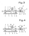
- the impact device 3 and the turret 19 with the marking punches 25 are located first in the in Fig. 3 shown working position in which the to be actuated marking punch 25 assumes the desired impact position relative to the product 34 to be marked.
- the firing pin 6 is aligned coaxially with the marking die 25.
- the pressing on the support collar 10 cam 14a holds by means of the servo motor 15, the firing pin 6 in the initial position shown, in which the striking spring 8 is tensioned and the firing pin 6 is slightly removed from the marking punch 25.
- the cam member 12 is rotated by the servo motor 15 so that the cam 14a pivots out of the support collar 10.
- the striking spring 8 relaxes abruptly and drives the firing pin 6 in the direction of the product to be marked.
- the firing pin 6 strikes the marking die 25 and gives it thereby a high kinetic energy, which causes the stamp can strike with a correspondingly high impact force in the product to be marked. This ensures the achievement of the prescribed standard depth.
- the turret 19 is rotated in advance until the marking stamp with the desired marker in the FIG. 3 has reached impact position shown. Subsequently, the marking process is carried out as described above. Accordingly, markings with several markings are used.
- the electromotive drive facilitates the programming of the overall control.
- the impact force of the striking spring 8 is finely adjusted by screwing in or unscrewing the support bearing 9 in the guide bushing 7a.
- the marking machine described is equipped with the rotatable turret 19 as a punch carrier, so that the individual marking punches 25 can be brought by turning the punch carrier in the desired impact position.
- a displacement device as a punch carrier, so that in this case the individual punches can be brought into striking position by displacing the punch carrier.
- a drive motor for the inventive impact device is any electrically powered motor in question, which can hold the striker 8 in the tensioned state, be it for example in conjunction with a suitable holding mechanism, either because he can exercise a corresponding moment in the dormant state.
Landscapes
- Shaping Metal By Deep-Drawing, Or The Like (AREA)
- Camera Data Copying Or Recording (AREA)
Description
- Die Erfindung betrifft eine Markierungsmaschine für metallurgische Erzeugnisse, insbesondere Stranggusserzeugnisse, mit mindestens einem Markierungsstempel sowie einer Schlagvorrichtung zum Einschlagen des Markierungsstempels in das zu markierende Erzeugnis.
- Derartige Maschinen dienen bekanntlich dazu, metallurgische Erzeugnisse, insbesondere Stranggusserzeugnisse wie Knüppel, Brammen u.ä., mit einer Markierung zu versehen, die sich aus einem oder mehreren aneinandergereihten Markierungszeichen zusammensetzt. Um die Markierung vorzunehmen, wird der mit dem Markierungszeichen versehene Stempel in Schlagstellung gebracht und anschliessend mit Hilfe der Schlagvorrichtung in das zu markierende Erzeugnis eingeschlagen. Hierbei wird eine möglichst grosse und gleichmässige Einschlagtiefe sowie eine möglichst schnelle Wiederholrate der Markierung angestrebt. Dies gilt auch insbesondere für Markierungen mit mehreren nacheinander in Einsatz kommenden Stempeln.
- Bei den bekannten Markierungsmaschinen der eingangs genannten Art ist die Schlagvorrichtung mit einem hydraulischen Antrieb ausgerüstet (
EP 0094369 A2 ). Wegen der hierfür erforderlichen Zylinder, Ventile, Verbindungsleitungen und sonstiger Ausrüstung ist sowohl der Gesamtaufbau als auch die Gesamtsteuerung aufwendig. Ausserdem ist ihre relativ langsame und wenig präzise Arbeitsweise von Nachteil. - Aus
US-A-1 743 840 , die den Oberbegriff bildet, ist eine Markierungsvorrichtung für Rohholzstücke bekannt, die eine Schlagvorrichtung zum Einschlagen eines Stempels aufweist. Mittels einer Handkurbel wird über ein Zahnrad ein Schlagbolzen, der mit einer Zahnstange versehen ist bewegt und dabei eine Schlagfeder spannt. Nach einem Auskuppeln des Zahnrades von der Zahnstange kann die Spannkraft der Schlagfeder auf den Schlagbolzen übertragen und ein an der Schlagvorrichtung befestigter Stempel in das Produkt eingeschlagen werden. Diese tragbar leichte Schlagvorrichtung ist geeignet, mittels des Stempels eine Identifikation z.B. an einem Baumstamm anzubringen. Für das Anbringen einer Summe von Identifikationen durch unterschiedliche Stempel innerhalb einer limitierten Zeitvorgabe ist diese Markierungsvorrichtung nicht geeignet. - Der Erfindung liegt die Aufgabe zugrunde, diese Nachteile zu vermeiden und eine Markierungsmaschine der eingangs genannten Art zu schaffen, deren Schlagvorrichtung sich durch einen einfachen und wartungsfreundlichen Aufbau sowie eine schnelle, präzise und betriebssichere Arbeitsweise auszeichnet.
- Diese Aufgabe wird erfindungsgemäss durch eine Markierungsmachine gemäß Anspruch 1 gelöst.
- Die erfindungsgemässe Federbeaufschlagung des Markierungsstempels verleiht diesem eine gleichmässig hohe kinetische Energie und bewirkt somit eine grosse und gleichmässige Einschlagtiefe der Markierung. In Verbindung mit dem elektromotorischen Antrieb ermöglicht sie einen schnellen, präzisen und leicht steuerbaren Ablauf der einzelnen Arbeitsschritte der Maschine, und trägt zuverlässig dazu bei, dass diese auch im rauhen Betrieb fehlerfrei arbeiten kann.
- Gemäss der Erfindung ist das Betätigungselement mit einem Elektromotor antreibbar, durch welchen die Schlagfeder spannbar ist, dann in gespanntem Zustand haltbar ist, und anschliessend gesteuert entspannbar ist.
- Zweckmässigerweise ist die Schlagfeder auf dem Schlagbolzen zwischen einem ortsfesten Stützlager und einem Stützbund des Schlagbolzens angeordnet, und durch ein gegen den Stützbund in Spannrichtung der Schlagfeder drückendes Nockenelement betätigbar.
- Um die Schlagfrequenz der Schlagvorrichtung zu erhöhen, weist das Nokkenelement erfindungsgemäss einen durch den Elektromotor drehbaren Nockenträger auf, der mit zwei diametral angeordneten Nocken versehen ist. Dadurch ist es möglich, durch Drehen des Nockenträgers die Schlagfeder mit dem einen Nocken zu spannen und sie danach schlagartig zu entspannen.
- Es ist im Sinne einer robusten und präzisen Axialführung des Schlagbolzens vorteilhaft, wenn die Schlagvorrichtung ein Traggestell mit Führungslagern für den Schlagbolzen aufweist und dessen Stützbund auf einem im Traggestell angeordneten Führungselement entlang gleitet.
- Zweckmässigerweise ist eines der Führungslager als ortsfestes Stützlager der Schlagfeder vorgesehen.
- Die Erfindung wird nachfolgend anhand eines Ausführungsbeispiels unter Bezugnahme auf die Zeichnung näher erläutert.
- Es zeigen:
- Fig. 1
- die Schlagvorrichtung der erfindungsgemässen Markierungsmaschine mit mehreren in einem Revolverkopf angeordneten Stempeln,
- Fig. 2
- einen Schnitt entlang der Linie II-II in
Fig. 1 , - Fig. 3
- die Schlagvorrichtung aus
Fig. 1 in gespannter Stellung, schematisch und etwas vergrössert dargestellt, und - Fig. 4
- die Schlagvorrichtung aus
Fig. 1 in entspannter Stellung, ebenfalls sche- matisch und etwas vergrössert dargestellt. - Die in den
Figuren 1 bis 4 dargestellte Markierungsmaschine weist ein Maschinengestell 1 mit einem darauf befestigten Traggehäuse 2 auf, in dem eine Schlagvorrichtung 3 und ein Stempelträger 4 eingebaut sind. - Wie aus den
Figuren 1 bis 4 ersichtlich, weist die Schlagvorrichtung 3 ein Traggestell 5 mit einem Schlagbolzen 6 auf, der axial in zwei Führungsbüchsen 7a, 7b geführt ist und durch eine auf ihm sitzende Schlagfeder 8 beaufschlagbar ist. Diese ist zwischen einem ortsfesten Stützlager 9 und einem im Schlagbolzen 6 vorgesehenen Stützbund 10 eingebaut. Das Stützlager 9 ist in der Führungsbüchse 7a eingeschraubt. Im Traggestell 5 ist ein Führungselement 11 für den Stützbund 10 des Schlagbolzens 6 angeordnet. - Die Schlagfeder 8 ist durch ein Betätigungselement in Gestalt eines Nockenelements 12 betätigbar, das durch einen Nockenträger 13 mit zwei diametral angeordneten Nocken 14a, 14b gebildet ist.
- Das Nockenelement 12 ist mit einem elektrischen Motor 15 über ein Schneckengetriebe 16 antreibbar, durch welches der auf seiner Abtriebswelle 17 sitzende Nockenträger 13 drehbar ist. Zwischen ihm und dem Servomotor 15 ist eine Kupplung 18 angeordnet.
- Wie aus der
Figur 1 ersichtlich, weist der Stempelträger 4 einen Revolverkopf 19 mit einer Drehachse 20 und zwei Führungsscheiben 21 a, 21 b auf. Die Drehachse 20 ist in einem Gehäuse 23 gelagert, das auf einer Tragplatte 24 befestigt ist. - Der Revolverkopf 19 trägt kranzförmig angeordnete Markierungsstempel 25 mit Stempelbolzen 26, die je eine Rückstellfeder 27 sowie ein stirnseitiges Markierungszeichen 28 aufweisen und in den Führungsscheiben 21 a, 21 b des Revolverkopfes 19 achsparallel zu dessen Drehachse 20 geführt sind.
- Der Revolverkopf 19 ist durch einen elektrischen Servomotor 29 über ein Zahnradgetriebe 30 mit einem am Revolverkopf 19 befestigten Zahnkranz 31 und einem auf der Antriebswelle 32 des Servomotors 29 sitzenden Ritzel 33 antreibbar.
- Die Arbeitsweise der vorstehend beschriebenen Markierungsmaschine ist wie folgt:
- Die Schlagvorrichtung 3 und der Revolverkopf 19 mit den Markierungsstempeln 25 befinden sich zunächst in der in
Fig. 3 dargestellten Arbeitsstellung, in welcher der zu betätigende Markierungsstempel 25 die gewünschte Einschlagstellung gegenüber dem zu markierenden Erzeugnis 34 einnimmt. Der Schlagbolzen 6 ist koaxial zum Markierungsstempel 25 ausgerichtet. Der auf den Stützbund 10 drückende Nocken 14a hält mit Hilfe des Servomotors 15 den Schlagbolzen 6 in der gezeigten Ausgangslage, in welcher die Schlagfeder 8 gespannt ist und der Schlagbolzen 6 etwas vom Markierungsstempel 25 entfernt ist. - Um den Markierungsvorgang auszulösen, wird das Nockenelement 12 durch den Servomotor 15 so gedreht, dass der Nocken 14a aus dem Stützbund 10 herausschwenkt. Dadurch entspannt sich die Schlagfeder 8 schlagartig und treibt den Schlagbolzen 6 in Richtung des zu markierenden Erzeugnisses. Der Schlagbolzen 6 schlägt auf den Markierungsstempel 25 und verleiht diesem dabei eine hohe kinetische Energie, die bewirkt, dass der Stempel mit entsprechend hoher Einschlagkraft in das zu markierende Erzeugnis einschlagen kann. Dies gewährleistet die Erzielung der vorgeschriebenen Normtiefe.
- Zur Wiederholung der Markierung wird nunmehr das Nockenelement 12 mit dem Servomotor 15 weitergedreht, bis der Nocken 14b auf den Stützbund 10 drückt und den Schlagbolzen 6 mit der Schlagfeder 8 in die in
Figur 3 gezeigte Stellung zurückführt. Danach wird der Vorgang wie vorstehend beschrieben fortgesetzt. - Um einen Markierungswechsel vorzunehmen, wird vorab der Revolverkopf 19 soweit gedreht bis der Markierungsstempel mit dem gewünschten Markierungszeichen die in der
Figur 3 gezeigte Einschlagstellung erreicht hat. Anschliessend wird der Markierungsvorgang wie vorstehend beschrieben durchgeführt. Dementsprechend wird bei Markierungen mit mehreren Markierungszeichen vorgegangen. - Durch den elektromotorischen Antrieb wird die Programmierung der Gesamtsteuerung erleichtert. Die Schlagkraft der Schlagfeder 8 ist durch Ein- oder Ausschrauben des Stützlagers 9 in der Führungsbüchse 7a fein einstellbar.
- Die beschriebene Markierungsmaschine ist mit dem drehbaren Revolverkopf 19 als Stempelträger ausgestattet, so dass die einzelnen Markierungsstempel 25 durch Drehen des Stempelträgers in die gewünschte Schlagstellung bringbar sind. Es ist aber auch im Rahmen der Erfindung ohne weiteres möglich, als Stempelträger beispielsweise eine Verschiebevorrichtung vorzusehen, so dass in diesem Fall die einzelnen Stempel durch Verschieben des Stempelträgers in Schlagstellung bringbar sind.
- Selbstverständlich ist es ebenfalls im Rahmen der Erfindung möglich, einen Stempelträger mit nur einem Markierungsstempel vorzusehen.
- Als Antriebsmotor für die erfindungsgemässe Schlagvorrichtung kommt jeder elektrisch betriebene Motor in Frage, der die Schlagfeder 8 im gespannten Zustand halten kann, sei es beispielsweise in Verbindung mit einem geeigneten Haltemechanismus, sei es weil er im ruhenden Zustand ein entsprechendes Moment ausüben kann.
Claims (8)
- Markierungsmaschine für metallurgische Erzeugnisse, insbesondere Stranggusserzeugnisse, bestehend aus einem Markierungsstempel (25) und einer Schlagvorrichtung (3) zum Einschlagen des Markierungsstempels (25) in das zu markierende Erzeugnis, wobei die Schlagvorrichtung (3) aus einem Schlagbolzen (6), einer den Schlagbolzen treibenden Schlagfeder (8) und Betätigungsvorrichtungen für das Spannen der Schlagfeder, für das Festhalten der gespannten Schlagfeder und für das Freigeben der gespannten Schlagfeder besteht, dadurch gekennzeichnet, dass eine gemeinsame Betätigungsvorrichtung, bestehend aus einem mittels Elektromotor angetriebenen Nockenelement (12) für das Spannen der Schlagfeder (8), für das Festhalten der gespannten Schlagfeder (8) und für das gesteuerte Freigeben der gespannten Schlagfeder (8) vorgesehen ist, wobei die Schlagvorrichtung (3) mit einem Stempelträger (4) mit mehreren Markierungsstempeln (25) zusammenwirkt und jeweils durch Verschieben oder Drehen des Stempelträgers ein vorbestimmter Stempel in eine koaxiale Schlagstellung mit dem Schlagbolzen bringbar ist und durch die gesteuerte Freigabe der Spannkraft der Schlagfeder (8) der vorbestimmte Markierungsstempel (25) das Erzeugnis markiert.
- Markierungsmaschine nach Anspruch 1, dadurch gekennzeichnet, dass die Schlagfeder (8) auf dem Schlagbolzen (6) zwischen einem ortsfesten Stützlager (9) und einem am Schlagbolzen (6) vorgesehenen Stützbund (10) angeordnet ist, und durch ein gegen den Stützbund (10) in Spannrichtung der Schlagfeder (8) drückendes Nockenelement (12) betätigbar ist.
- Markierungsmaschine nach Anspruch 1 oder 2, dadurch gekennzeichnet, dass das Nockenelement (12) einen durch den Elektromotor (15) drehbaren Nockenträger (13) aufweist, der mit zwei diametral angeordneten Nocken (14a, 14b) versehen ist.
- Markierungsmaschine nach einem der Ansprüche 1 - 3, dadurch gekennzeichnet, dass das Nockenelement (12) über ein Schneckengetriebe (16) antreibbar ist.
- Markierungsmaschine nach einem der Ansprüche 2 - 4, dadurch gekennzeichnet, dass die Schlagvorrichtung (3) ein Traggestell (5) mit Führungsbüchsen (7a, 7b) für den Schlagbolzen (6) aufweist und der Stützbund (10) auf einem im Traggehäuse (5) angeordneten Führungselement (11) entlanggleitet.
- Markierungsmaschine nach Anspruch 5, dadurch gekennzeichnet, dass die eine Führungsbüchse (7a) als ortsfestes Stützlager (9) für die Schlagfeder (8) dient.
- Markierungsmaschine nach einem der Ansprüche 1 - 6, dadurch gekennzeichnet, dass der Stempelträger (4) mit mehreren Markierungsstempeln (25) als drehbarer Revolverkopf (19) ausgebildet ist.
- Markierungsmaschine nach einem der Ansprüche 5 - 7, dadurch gekennzeichnet, dass die Schlagkraft der Schlagfeder (8) durch Ein- oder Ausschrauben des Stützlagers (9) in der Führungsbüchse (7a) einstellbar ist.
Applications Claiming Priority (3)
| Application Number | Priority Date | Filing Date | Title |
|---|---|---|---|
| CH384022002 | 2002-03-05 | ||
| CH3842002 | 2002-03-05 | ||
| PCT/EP2003/001884 WO2003074295A1 (de) | 2002-03-05 | 2003-02-25 | Markierungsmaschine für metallurgische erzeugnisse |
Publications (2)
| Publication Number | Publication Date |
|---|---|
| EP1480841A1 EP1480841A1 (de) | 2004-12-01 |
| EP1480841B1 true EP1480841B1 (de) | 2010-09-01 |
Family
ID=27768324
Family Applications (1)
| Application Number | Title | Priority Date | Filing Date |
|---|---|---|---|
| EP03718675A Expired - Lifetime EP1480841B1 (de) | 2002-03-05 | 2003-02-25 | Markierungsmaschine für metallurgische erzeugnisse |
Country Status (9)
| Country | Link |
|---|---|
| US (1) | US7421876B2 (de) |
| EP (1) | EP1480841B1 (de) |
| JP (1) | JP4411081B2 (de) |
| KR (1) | KR100941114B1 (de) |
| AT (1) | ATE479559T1 (de) |
| BR (1) | BR0308150B1 (de) |
| DE (1) | DE50313036D1 (de) |
| ES (1) | ES2351964T3 (de) |
| WO (1) | WO2003074295A1 (de) |
Families Citing this family (2)
| Publication number | Priority date | Publication date | Assignee | Title |
|---|---|---|---|---|
| EP1972930B1 (de) | 2007-03-19 | 2019-11-13 | Concast Ag | Verfahren zur Erkennung von Oberflächenmerkmalen metallurgischer Erzeugnisse, insbesondere Strangguss- und Walzerzeugnisse, sowie eine Einrichtung zur Durchführung des Verfahrens |
| EP2781364B1 (de) * | 2013-03-18 | 2015-05-06 | schoen + sandt machinery GmbH | Prägevorrichtung |
Family Cites Families (14)
| Publication number | Priority date | Publication date | Assignee | Title |
|---|---|---|---|---|
| US580580A (en) * | 1897-04-13 | Island | ||
| US1284100A (en) * | 1918-02-12 | 1918-11-05 | William R Hart | Riveting-machine. |
| US1518549A (en) * | 1920-07-30 | 1924-12-09 | Edward Ogden J | Spring hammer |
| US1491285A (en) * | 1923-04-19 | 1924-04-22 | Said Said Blake | Automatic hammer |
| US1747842A (en) * | 1927-12-09 | 1930-02-18 | John E Phillips | Calking or tamping tool |
| US1743840A (en) * | 1928-10-16 | 1930-01-14 | Jas H Matthews & Company | Power-driven hammer |
| US2455270A (en) * | 1943-02-26 | 1948-11-30 | Sarl Mermet & Virthner | Automatic striking tool |
| US2475398A (en) * | 1947-06-24 | 1949-07-05 | Montoya Carlos | Mechanical hammer |
| FR2343531A1 (fr) * | 1976-03-10 | 1977-10-07 | Laffay Gilbert | Dispositif a frappe automatique pour le marquage, poinconnage, rivetage ou similaire |
| AT373511B (de) | 1982-05-10 | 1984-01-25 | Stangl Kurt Dipl Ing | Vorrichtung zum einschlagen verschiedener praegezeichen in huetten- oder walzprodukte |
| NL8921208A (nl) * | 1988-11-18 | 1990-11-01 | Amada Co Ltd | Revolverponsmachine. |
| JPH074129Y2 (ja) * | 1990-05-28 | 1995-02-01 | レジター・パワー・トゥールズ・カンパニー・リミテッド | 電動釘打ち機 |
| JPH07144233A (ja) * | 1993-11-22 | 1995-06-06 | Akira Taniura | 加工装置 |
| US20010042453A1 (en) * | 1999-10-14 | 2001-11-22 | Albrecht Schneider | Method and apparatus for marking workpieces |
-
2003
- 2003-02-25 EP EP03718675A patent/EP1480841B1/de not_active Expired - Lifetime
- 2003-02-25 US US10/505,704 patent/US7421876B2/en not_active Expired - Fee Related
- 2003-02-25 DE DE50313036T patent/DE50313036D1/de not_active Expired - Lifetime
- 2003-02-25 KR KR1020047013683A patent/KR100941114B1/ko not_active Expired - Fee Related
- 2003-02-25 JP JP2003572782A patent/JP4411081B2/ja not_active Expired - Fee Related
- 2003-02-25 BR BRPI0308150-8B1A patent/BR0308150B1/pt not_active IP Right Cessation
- 2003-02-25 WO PCT/EP2003/001884 patent/WO2003074295A1/de not_active Ceased
- 2003-02-25 ES ES03718675T patent/ES2351964T3/es not_active Expired - Lifetime
- 2003-02-25 AT AT03718675T patent/ATE479559T1/de active
Also Published As
| Publication number | Publication date |
|---|---|
| KR20040089697A (ko) | 2004-10-21 |
| BR0308150A (pt) | 2005-01-11 |
| JP2005518968A (ja) | 2005-06-30 |
| ATE479559T1 (de) | 2010-09-15 |
| ES2351964T3 (es) | 2011-02-14 |
| US7421876B2 (en) | 2008-09-09 |
| KR100941114B1 (ko) | 2010-02-10 |
| EP1480841A1 (de) | 2004-12-01 |
| BR0308150B1 (pt) | 2013-09-10 |
| JP4411081B2 (ja) | 2010-02-10 |
| WO2003074295A1 (de) | 2003-09-12 |
| DE50313036D1 (de) | 2010-10-14 |
| US20050061053A1 (en) | 2005-03-24 |
Similar Documents
| Publication | Publication Date | Title |
|---|---|---|
| EP3025358B1 (de) | Elektromagnetische stellvorrichtung und system zur verstellung einer funktionalität eines kraftfahrzeugaggregats | |
| DE69907611T2 (de) | Anordnung zur befestigung eines stanzwerkzeuges in einer rotationsstanzmaschine für laminiertes material | |
| EP1993335B1 (de) | Stanzeinrichtung mit Wechselstempel und variablem Stanzmuster | |
| DE2725526A1 (de) | Verfahren zur herstellung eines dosendeckels mit schwaechungsritze zum aufreissen desselben, vorrichtung zur durchfuehrung dieses verfahrens und nach diesem verfahren hergestellter dosendeckel | |
| CH647699A5 (de) | Antriebseinrichtung fuer biegeschlitten von stanz-biegeautomaten. | |
| EP2082867A2 (de) | Tablettenpresse | |
| DE4494432B4 (de) | Stanzpresse mit einem Werkzeugmagazin | |
| DE1577246C3 (de) | Sicherungseinrichtung für Arbeitsmaschinen | |
| DE3121188A1 (de) | "markierungsvorrichtung" | |
| EP0519865A1 (de) | Vorrichtung zum Biegen von Draht oder dergleichen | |
| DE3402010C2 (de) | Vorrichtung zum Entrosten von Eisenteilen | |
| EP1497066B1 (de) | Getriebemittel für eine schneideinrichtung | |
| EP1480841A1 (de) | Markierungsmaschine f r metallurgische erzeugnisse | |
| DE2728058C3 (de) | Stempelmaschine zur Kennzeichnung von Hütten- und Walzprodukten | |
| DE3144397C2 (de) | Einzeltypenprägevorrrichtung | |
| DE10359879A1 (de) | Hydraulische Bearbeitungszange | |
| DE1952036A1 (de) | Praegeverfahren und -vorrichtung | |
| DE3030910C2 (de) | ||
| DE961925C (de) | Einrichtung an Vorsatzgeraeten fuer tragbare, durch elektrischen Handmotor angetriebene Werkzeuge | |
| DE3522251C1 (en) | Machine for engraving alphanumeric or other characters into workpieces | |
| EP0980818A2 (de) | Spannvorrichtung | |
| DE1652401B2 (de) | Markierungsvorrichtung fuer walzgut | |
| DE60001110T2 (de) | Vorrichtung zum entkernen von gussstücken | |
| DE1652327A1 (de) | Vorrichtung zum wahlweisen Aufbringen von Praegezeichen auf ein Werkstueck | |
| DE929782C (de) | Lochstanze, insbesondere zur Herstellung von gelochten Blechen |
Legal Events
| Date | Code | Title | Description |
|---|---|---|---|
| PUAI | Public reference made under article 153(3) epc to a published international application that has entered the european phase |
Free format text: ORIGINAL CODE: 0009012 |
|
| 17P | Request for examination filed |
Effective date: 20040809 |
|
| AK | Designated contracting states |
Kind code of ref document: A1 Designated state(s): AT BE BG CH CY CZ DE DK EE ES FI FR GB GR HU IE IT LI LU MC NL PT SE SI SK TR |
|
| 17Q | First examination report despatched |
Effective date: 20080520 |
|
| GRAP | Despatch of communication of intention to grant a patent |
Free format text: ORIGINAL CODE: EPIDOSNIGR1 |
|
| GRAS | Grant fee paid |
Free format text: ORIGINAL CODE: EPIDOSNIGR3 |
|
| GRAA | (expected) grant |
Free format text: ORIGINAL CODE: 0009210 |
|
| AK | Designated contracting states |
Kind code of ref document: B1 Designated state(s): AT BE BG CH CY CZ DE DK EE ES FI FR GB GR HU IE IT LI LU MC NL PT SE SI SK TR |
|
| REG | Reference to a national code |
Ref country code: GB Ref legal event code: FG4D Free format text: NOT ENGLISH |
|
| REG | Reference to a national code |
Ref country code: CH Ref legal event code: EP |
|
| REG | Reference to a national code |
Ref country code: IE Ref legal event code: FG4D Free format text: LANGUAGE OF EP DOCUMENT: GERMAN |
|
| REF | Corresponds to: |
Ref document number: 50313036 Country of ref document: DE Date of ref document: 20101014 Kind code of ref document: P |
|
| REG | Reference to a national code |
Ref country code: CH Ref legal event code: NV Representative=s name: LUCHS & PARTNER AG PATENTANWAELTE |
|
| REG | Reference to a national code |
Ref country code: PT Ref legal event code: SC4A Free format text: AVAILABILITY OF NATIONAL TRANSLATION Effective date: 20101103 |
|
| REG | Reference to a national code |
Ref country code: NL Ref legal event code: T3 |
|
| REG | Reference to a national code |
Ref country code: SE Ref legal event code: TRGR |
|
| REG | Reference to a national code |
Ref country code: SK Ref legal event code: T3 Ref document number: E 8203 Country of ref document: SK |
|
| REG | Reference to a national code |
Ref country code: ES Ref legal event code: FG2A Effective date: 20110202 |
|
| PG25 | Lapsed in a contracting state [announced via postgrant information from national office to epo] |
Ref country code: CY Free format text: LAPSE BECAUSE OF FAILURE TO SUBMIT A TRANSLATION OF THE DESCRIPTION OR TO PAY THE FEE WITHIN THE PRESCRIBED TIME-LIMIT Effective date: 20100901 Ref country code: SI Free format text: LAPSE BECAUSE OF FAILURE TO SUBMIT A TRANSLATION OF THE DESCRIPTION OR TO PAY THE FEE WITHIN THE PRESCRIBED TIME-LIMIT Effective date: 20100901 |
|
| REG | Reference to a national code |
Ref country code: IE Ref legal event code: FD4D |
|
| PG25 | Lapsed in a contracting state [announced via postgrant information from national office to epo] |
Ref country code: GR Free format text: LAPSE BECAUSE OF FAILURE TO SUBMIT A TRANSLATION OF THE DESCRIPTION OR TO PAY THE FEE WITHIN THE PRESCRIBED TIME-LIMIT Effective date: 20101202 |
|
| PG25 | Lapsed in a contracting state [announced via postgrant information from national office to epo] |
Ref country code: IE Free format text: LAPSE BECAUSE OF FAILURE TO SUBMIT A TRANSLATION OF THE DESCRIPTION OR TO PAY THE FEE WITHIN THE PRESCRIBED TIME-LIMIT Effective date: 20100901 |
|
| PG25 | Lapsed in a contracting state [announced via postgrant information from national office to epo] |
Ref country code: EE Free format text: LAPSE BECAUSE OF FAILURE TO SUBMIT A TRANSLATION OF THE DESCRIPTION OR TO PAY THE FEE WITHIN THE PRESCRIBED TIME-LIMIT Effective date: 20100901 |
|
| PLBE | No opposition filed within time limit |
Free format text: ORIGINAL CODE: 0009261 |
|
| STAA | Information on the status of an ep patent application or granted ep patent |
Free format text: STATUS: NO OPPOSITION FILED WITHIN TIME LIMIT |
|
| 26N | No opposition filed |
Effective date: 20110606 |
|
| PG25 | Lapsed in a contracting state [announced via postgrant information from national office to epo] |
Ref country code: DK Free format text: LAPSE BECAUSE OF FAILURE TO SUBMIT A TRANSLATION OF THE DESCRIPTION OR TO PAY THE FEE WITHIN THE PRESCRIBED TIME-LIMIT Effective date: 20100901 |
|
| PG25 | Lapsed in a contracting state [announced via postgrant information from national office to epo] |
Ref country code: MC Free format text: LAPSE BECAUSE OF NON-PAYMENT OF DUE FEES Effective date: 20110228 |
|
| REG | Reference to a national code |
Ref country code: DE Ref legal event code: R097 Ref document number: 50313036 Country of ref document: DE Effective date: 20110606 |
|
| PGFP | Annual fee paid to national office [announced via postgrant information from national office to epo] |
Ref country code: LU Payment date: 20130221 Year of fee payment: 11 |
|
| PGFP | Annual fee paid to national office [announced via postgrant information from national office to epo] |
Ref country code: SE Payment date: 20130219 Year of fee payment: 11 Ref country code: FR Payment date: 20130301 Year of fee payment: 11 Ref country code: GB Payment date: 20130218 Year of fee payment: 11 Ref country code: FI Payment date: 20130213 Year of fee payment: 11 |
|
| PGFP | Annual fee paid to national office [announced via postgrant information from national office to epo] |
Ref country code: NL Payment date: 20130219 Year of fee payment: 11 Ref country code: SK Payment date: 20130222 Year of fee payment: 11 |
|
| PGFP | Annual fee paid to national office [announced via postgrant information from national office to epo] |
Ref country code: PT Payment date: 20130218 Year of fee payment: 11 |
|
| PG25 | Lapsed in a contracting state [announced via postgrant information from national office to epo] |
Ref country code: BG Free format text: LAPSE BECAUSE OF FAILURE TO SUBMIT A TRANSLATION OF THE DESCRIPTION OR TO PAY THE FEE WITHIN THE PRESCRIBED TIME-LIMIT Effective date: 20101201 |
|
| PG25 | Lapsed in a contracting state [announced via postgrant information from national office to epo] |
Ref country code: HU Free format text: LAPSE BECAUSE OF FAILURE TO SUBMIT A TRANSLATION OF THE DESCRIPTION OR TO PAY THE FEE WITHIN THE PRESCRIBED TIME-LIMIT Effective date: 20100901 |
|
| PGFP | Annual fee paid to national office [announced via postgrant information from national office to epo] |
Ref country code: CH Payment date: 20140226 Year of fee payment: 12 |
|
| PGFP | Annual fee paid to national office [announced via postgrant information from national office to epo] |
Ref country code: BE Payment date: 20140218 Year of fee payment: 12 |
|
| REG | Reference to a national code |
Ref country code: PT Ref legal event code: MM4A Free format text: LAPSE DUE TO NON-PAYMENT OF FEES Effective date: 20140825 |
|
| REG | Reference to a national code |
Ref country code: NL Ref legal event code: V1 Effective date: 20140901 |
|
| PG25 | Lapsed in a contracting state [announced via postgrant information from national office to epo] |
Ref country code: LU Free format text: LAPSE BECAUSE OF NON-PAYMENT OF DUE FEES Effective date: 20140225 |
|
| REG | Reference to a national code |
Ref country code: SE Ref legal event code: EUG |
|
| GBPC | Gb: european patent ceased through non-payment of renewal fee |
Effective date: 20140225 |
|
| PG25 | Lapsed in a contracting state [announced via postgrant information from national office to epo] |
Ref country code: FI Free format text: LAPSE BECAUSE OF NON-PAYMENT OF DUE FEES Effective date: 20140225 Ref country code: NL Free format text: LAPSE BECAUSE OF NON-PAYMENT OF DUE FEES Effective date: 20140901 |
|
| REG | Reference to a national code |
Ref country code: SK Ref legal event code: MM4A Ref document number: E 8203 Country of ref document: SK Effective date: 20140225 |
|
| REG | Reference to a national code |
Ref country code: FR Ref legal event code: ST Effective date: 20141031 |
|
| PG25 | Lapsed in a contracting state [announced via postgrant information from national office to epo] |
Ref country code: SE Free format text: LAPSE BECAUSE OF NON-PAYMENT OF DUE FEES Effective date: 20140226 Ref country code: SK Free format text: LAPSE BECAUSE OF NON-PAYMENT OF DUE FEES Effective date: 20140225 |
|
| PG25 | Lapsed in a contracting state [announced via postgrant information from national office to epo] |
Ref country code: PT Free format text: LAPSE BECAUSE OF NON-PAYMENT OF DUE FEES Effective date: 20140825 |
|
| PG25 | Lapsed in a contracting state [announced via postgrant information from national office to epo] |
Ref country code: FR Free format text: LAPSE BECAUSE OF NON-PAYMENT OF DUE FEES Effective date: 20140228 Ref country code: GB Free format text: LAPSE BECAUSE OF NON-PAYMENT OF DUE FEES Effective date: 20140225 |
|
| PG25 | Lapsed in a contracting state [announced via postgrant information from national office to epo] |
Ref country code: BE Free format text: LAPSE BECAUSE OF NON-PAYMENT OF DUE FEES Effective date: 20150228 |
|
| REG | Reference to a national code |
Ref country code: CH Ref legal event code: PL |
|
| PG25 | Lapsed in a contracting state [announced via postgrant information from national office to epo] |
Ref country code: LI Free format text: LAPSE BECAUSE OF NON-PAYMENT OF DUE FEES Effective date: 20150228 Ref country code: CH Free format text: LAPSE BECAUSE OF NON-PAYMENT OF DUE FEES Effective date: 20150228 |
|
| PGFP | Annual fee paid to national office [announced via postgrant information from national office to epo] |
Ref country code: CZ Payment date: 20170123 Year of fee payment: 15 |
|
| PGFP | Annual fee paid to national office [announced via postgrant information from national office to epo] |
Ref country code: TR Payment date: 20170213 Year of fee payment: 15 Ref country code: ES Payment date: 20170213 Year of fee payment: 15 |
|
| PG25 | Lapsed in a contracting state [announced via postgrant information from national office to epo] |
Ref country code: CZ Free format text: LAPSE BECAUSE OF NON-PAYMENT OF DUE FEES Effective date: 20180225 |
|
| REG | Reference to a national code |
Ref country code: ES Ref legal event code: FD2A Effective date: 20190801 |
|
| PG25 | Lapsed in a contracting state [announced via postgrant information from national office to epo] |
Ref country code: ES Free format text: LAPSE BECAUSE OF NON-PAYMENT OF DUE FEES Effective date: 20180226 |
|
| PGFP | Annual fee paid to national office [announced via postgrant information from national office to epo] |
Ref country code: DE Payment date: 20220217 Year of fee payment: 20 Ref country code: AT Payment date: 20220217 Year of fee payment: 20 |
|
| PGFP | Annual fee paid to national office [announced via postgrant information from national office to epo] |
Ref country code: IT Payment date: 20220217 Year of fee payment: 20 |
|
| PG25 | Lapsed in a contracting state [announced via postgrant information from national office to epo] |
Ref country code: TR Free format text: LAPSE BECAUSE OF NON-PAYMENT OF DUE FEES Effective date: 20180225 |
|
| REG | Reference to a national code |
Ref country code: DE Ref legal event code: R071 Ref document number: 50313036 Country of ref document: DE |
|
| REG | Reference to a national code |
Ref country code: AT Ref legal event code: MK07 Ref document number: 479559 Country of ref document: AT Kind code of ref document: T Effective date: 20230225 |