EP1479934A2 - Train d'entraínement - Google Patents
Train d'entraínement Download PDFInfo
- Publication number
- EP1479934A2 EP1479934A2 EP04010615A EP04010615A EP1479934A2 EP 1479934 A2 EP1479934 A2 EP 1479934A2 EP 04010615 A EP04010615 A EP 04010615A EP 04010615 A EP04010615 A EP 04010615A EP 1479934 A2 EP1479934 A2 EP 1479934A2
- Authority
- EP
- European Patent Office
- Prior art keywords
- drive train
- transmission
- clutch
- train according
- actuating mechanism
- Prior art date
- Legal status (The legal status is an assumption and is not a legal conclusion. Google has not performed a legal analysis and makes no representation as to the accuracy of the status listed.)
- Granted
Links
Images

Classifications
-
- F—MECHANICAL ENGINEERING; LIGHTING; HEATING; WEAPONS; BLASTING
- F16—ENGINEERING ELEMENTS AND UNITS; GENERAL MEASURES FOR PRODUCING AND MAINTAINING EFFECTIVE FUNCTIONING OF MACHINES OR INSTALLATIONS; THERMAL INSULATION IN GENERAL
- F16D—COUPLINGS FOR TRANSMITTING ROTATION; CLUTCHES; BRAKES
- F16D21/00—Systems comprising a plurality of actuated clutches
- F16D21/02—Systems comprising a plurality of actuated clutches for interconnecting three or more shafts or other transmission members in different ways
- F16D21/06—Systems comprising a plurality of actuated clutches for interconnecting three or more shafts or other transmission members in different ways at least two driving shafts or two driven shafts being concentric
-
- A—HUMAN NECESSITIES
- A21—BAKING; EDIBLE DOUGHS
- A21C—MACHINES OR EQUIPMENT FOR MAKING OR PROCESSING DOUGHS; HANDLING BAKED ARTICLES MADE FROM DOUGH
- A21C11/00—Other machines for forming the dough into its final shape before cooking or baking
- A21C11/16—Extruding machines
- A21C11/20—Extruding machines with worms
-
- A—HUMAN NECESSITIES
- A21—BAKING; EDIBLE DOUGHS
- A21C—MACHINES OR EQUIPMENT FOR MAKING OR PROCESSING DOUGHS; HANDLING BAKED ARTICLES MADE FROM DOUGH
- A21C1/00—Mixing or kneading machines for the preparation of dough
- A21C1/06—Mixing or kneading machines for the preparation of dough with horizontally-mounted mixing or kneading tools; Worm or screw mixers
- A21C1/065—Worm or screw mixers, e.g. with consecutive mixing receptacles
-
- A—HUMAN NECESSITIES
- A21—BAKING; EDIBLE DOUGHS
- A21C—MACHINES OR EQUIPMENT FOR MAKING OR PROCESSING DOUGHS; HANDLING BAKED ARTICLES MADE FROM DOUGH
- A21C1/00—Mixing or kneading machines for the preparation of dough
- A21C1/14—Structural elements of mixing or kneading machines; Parts; Accessories
- A21C1/1405—Tools
- A21C1/141—Tools having mixing or cutting elements essentially perpendicular to their axes
-
- A—HUMAN NECESSITIES
- A21—BAKING; EDIBLE DOUGHS
- A21C—MACHINES OR EQUIPMENT FOR MAKING OR PROCESSING DOUGHS; HANDLING BAKED ARTICLES MADE FROM DOUGH
- A21C11/00—Other machines for forming the dough into its final shape before cooking or baking
- A21C11/10—Other machines for forming the dough into its final shape before cooking or baking combined with cutting apparatus
-
- B—PERFORMING OPERATIONS; TRANSPORTING
- B60—VEHICLES IN GENERAL
- B60K—ARRANGEMENT OR MOUNTING OF PROPULSION UNITS OR OF TRANSMISSIONS IN VEHICLES; ARRANGEMENT OR MOUNTING OF PLURAL DIVERSE PRIME-MOVERS IN VEHICLES; AUXILIARY DRIVES FOR VEHICLES; INSTRUMENTATION OR DASHBOARDS FOR VEHICLES; ARRANGEMENTS IN CONNECTION WITH COOLING, AIR INTAKE, GAS EXHAUST OR FUEL SUPPLY OF PROPULSION UNITS IN VEHICLES
- B60K23/00—Arrangement or mounting of control devices for vehicle transmissions, or parts thereof, not otherwise provided for
- B60K23/02—Arrangement or mounting of control devices for vehicle transmissions, or parts thereof, not otherwise provided for for main transmission clutches
-
- F—MECHANICAL ENGINEERING; LIGHTING; HEATING; WEAPONS; BLASTING
- F16—ENGINEERING ELEMENTS AND UNITS; GENERAL MEASURES FOR PRODUCING AND MAINTAINING EFFECTIVE FUNCTIONING OF MACHINES OR INSTALLATIONS; THERMAL INSULATION IN GENERAL
- F16D—COUPLINGS FOR TRANSMITTING ROTATION; CLUTCHES; BRAKES
- F16D21/00—Systems comprising a plurality of actuated clutches
- F16D21/02—Systems comprising a plurality of actuated clutches for interconnecting three or more shafts or other transmission members in different ways
- F16D21/06—Systems comprising a plurality of actuated clutches for interconnecting three or more shafts or other transmission members in different ways at least two driving shafts or two driven shafts being concentric
- F16D2021/0684—Mechanically actuated clutches with two clutch plates
Definitions
- the invention relates to a drive train with a clutch unit for torque transmission between an engine and a transmission.
- clutch units which include at least one friction clutch, via which the engine and the gearbox drivingly connected to each other and from each other can be coupled.
- the present invention has for its object to provide a drive train of the above called type to create an improved function and a simple structure has and ensures a cost-effective production. Furthermore, the inventive Driveline be particularly easy to use, so that a relatively inexpensive actuation system can be used. Also should by the particular embodiment and mode of action of an inventively designed Clutch unit whose assembly between the engine and transmission improved or be optimized and the originating from the engine axial and tumbling vibrations be isolated ..
- the invention for a drive train with a Double clutch can be used.
- the double clutch can have two clutch discs, each with a Transmission input shaft are connectable.
- the transmission can be in an advantageous manner form a so-called power shift transmission.
- one of the clutches can also for a power take-off over which, for example, auxiliary units are driven used become.
- the coupling unit via an actuating mechanism be engaged and disengaged, which is integrated in this coupling unit.
- the Actuating mechanism can be arranged in the coupling unit or be supported that the clutch actuation forces or clutch closing forces be intercepted within the coupling unit; that means in that the components forming the coupling unit are the actuating mechanism in such a way supported, that the power flow generated by these forces within these components closes.
- the actuating mechanism via a bearing supported on a housing of the coupling unit.
- the actuating mechanism in both the axial and in the radial Direction be positioned within the coupling unit.
- At least one component of the actuating mechanism can also be used for the transmission side centered pre-assembly of the coupling unit can be used.
- This component can by a non-rotatable component of the Betuschistsmechanismusses be formed.
- At least one clutch disc of the clutch unit in a pre-centered position be kept centered within the corresponding friction clutch, so that at the transmission-side pre-assembly of the corresponding sub-module via the on a transmission input shaft slidable hub of the clutch disc at least one centering support can be guaranteed.
- the clutch unit can be a so-called two-mass system form, wherein the two masses on the torsional vibration damper torsionally are coupled.
- the connectable to the output shaft of the engine components of the Torsional vibration damper can thereby form at least part of a primary mass.
- both clutches are forcibly closable, that is, that for torque transmission required contact pressure for the individual friction clutches over the Actuating system is initiated.
- at least one or even both friction clutches constructed in such a way are that they have an energy storage - such as a diaphragm spring - which at least required for torque transmission contact force partially, preferably completely, applies. If the energy storage only a part the application of the required contact force, the must for a slip-free torque transmission necessary additional part of the contact pressure on the actuation system of appropriate coupling can be applied.
- the couplings can be pulled as or depressed couplings may be formed.
- a combination of two is different Coupling types possible.
- the coupling unit find a pulled and a depressed clutch use.
- Farther can act on the release means, such as the diaphragm spring tongues, acting Actuating systems be designed so that they both on this release means Force in the closing direction and in the opening direction of the corresponding friction clutch exercise.
- a first disc part be axially flexible to compensate for axial and / or tumbling vibration can be designed.
- This first disc part can be used in conjunction with a second axially flexible disc part, the motor side receives the clutch unit, a damping unit form, with the two stiffnesses of the disc parts matched. It has been found that it can be particularly advantageous if the axial stiffness of the second disc part is larger than that of the first disc part.
- the first disc part can be configured in this way be that an overall substantially neutral support of the clutch unit can be done in such a way that at locations where the gear housing wall Has axial elevations, for example, on the bearing eyes of the gearbox and - Output shaft, the first disc part can be cut out, so that it from the axial Surveys is penetrated.
- the attachment of the first disc part in the region of Be outside circumference allowing for axial flexibility between the connection points of the clutch unit and the transmission housing an optimal radius available stands. Furthermore, the attachment radially outward on the transmission housing in areas take place, in which an attachment from the outside is easily accessible.
- the actuating device for example the first disc part, positioning means for fixing the rotational position between disc part and gear housing before and / or have in the assembly of the engine housing and gear housing.
- the actuating mechanism may be a mechanically or electrically operated from the outside Lever mechanism or ramp mechanism be, by means of pulling or rotating movements an axially directed along the transmission input shaft lifting movement for actuating one or more couplings performs.
- These include, for example, the patent application DE 103 13 739, WO00 / 15971 and DE 44 31 641 mentioned.
- the actuating mechanism concentric about the transmission input shaft arranged slave cylinder the one or more, for example radially superposed ring cylinder has.
- the actuating mechanism concentric about the transmission input shaft arranged slave cylinder the one or more, for example radially superposed ring cylinder has.
- hydraulic actuated ring cylinders or via externally operated release units can be distributed over the circumference around the transmission input shaft distributed piston / cylinder units be provided in the case of two clutches on the same or different radius can be arranged.
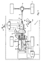
- Figure 1 shows schematically a motor vehicle 1 with a drive train, the one as Engine formed drive motor 2, a clutch unit 3 and a transmission 4 contains. About a drive shaft 5 and a differential 6, the wheels 7 of the Vehicle 1 powered. Naturally, it can also be a vehicle to act with one or more other driven axles.
- the control device 10,11 can as a unit or be formed in structurally and / or functionally separate subareas. if the Control device 10,11 formed in structurally and / or functionally separate sub-areas These can, for example, via a CAN bus 12 or another electrical Connection to communicate with each other.
- the control device For example, 10,11 controls the automated operation of the transmission 4 and / or the to the clutch unit 3 belonging clutches 13, 14 or the engine 2, for example the engine torque, the choice of gear ratio, a parking position or a Neutral position of the transmission 4 or the transferable from the clutches 13, 14 torque.
- the clutches 13, 14 are preferably automatically actuated by means of an actuator 15, wherein the clutches 13, 14 can be operated independently of each other.
- the actuators 15 for the clutch actuation of the clutches 13, 14 may be in a structural and / or functional unit or in example, the individual clutches 13, 14 assigned Subareas are executed.
- the means for changing the transmission ratio of the transmission comprises at least transmission actuators 16, 17, wherein each of the transmission actuators 16, 17 for actuating a group of translation stages may be provided, each associated with one of the clutches 13, 14.
- the groups of translation stages may be formed such that the Translation stages in terms of their translation form an order, so that adjacent translation stages each assigned to different clutches 13, 14 can be.
- the clutch unit 3 thus enables one for one Lastschaltenburg necessary actuation of the clutches 13, 14 in passing Change to traction interruption or traction interruption-free shifting.
- the translation of the transmission 4 is by a control of the actuators 16, 17 changeable.
- the actuators 16, 17 can for example, two drives each for generating a switching or selection movement include.
- the clutch unit 3 is by the control device 10 by means of the actuator 15 automated actuated.
- the controller 44 receives signals indicating the transmission state of the Clutches 13 and / or 14 and the transmission ratios set in the transmission 4 at least represent, as well as, if necessary, signals from a sensor 18 for the Output speed and a sensor 9 on the Rahs stress 8. This Signals are detected by sensors, such as from a gear detection sensor or a clutch travel sensor.
- Area 11 of the control device controls the engine 2 via an adjustment the throttle and / or the injection 19.
- the invention of course with all kinds of Drive motors are used.
- the transmission actuators 16, 17 include, for example, two each Electric motors, wherein a first electric motor for actuating the election process is controlled and a second electric motor for actuating the switching operation is controlled. For this purpose, by means of the electric motors along the Wählplex or the Switching path an adjustment of at least one transmission-side switching element actuated.
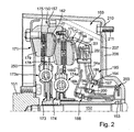
- the clutch unit 103 shown in Figure 2 comprises a coupling unit with a dual clutch 150, which is a driving shaft, in particular the crankshaft 151 an internal combustion engine with two drivable waves, in particular transmission input shafts 152, 153 connect and can separate from these.
- the double clutch 150 may be via a vibration damper such as by means of a dual mass flywheel be connected to the engine, in the illustrated embodiment, this is However, axially elastic means of the disc part 250 on the crankshaft in the circumferential direction rigidly received.
- the disk part 250 is over radially inner portions with the Crankshaft 151 - here by means of screws 156 - firmly connected and is through a sheet metal part formed, which radially outwardly carries the flywheel 157.
- the clutch unit or dual clutch 150 has two friction clutches 171, 172, each having a clutch disc 173, 174 with integrated torsional vibration damper 173a, 174a, which are at least substantially the ones registered by the engine Filter torsional vibrations, so that at least not fully on the transmission shafts 152, 153.
- the clutch disc 173 is on the inner Shaft 152 and the clutch plate 174 on the hollow outer, coaxial Wave 153 added. Radially outside have the clutch plates 173, 174th Friction areas, which in the illustrated embodiment by annular friction linings 175, 176 are formed. That is the pressure plate 162 for the friction clutch 171 forming annular member 162 is connected to a further annular member 177, which forms the counter-pressure plate for the friction clutch 172. pressure plate 162 and counter-pressure plate 177 are rotationally connected to each other via toothing regions 178 connected.
- the friction clutch 172 has a pressure plate 180, the counter pressure plate 179 of the friction clutch 171 is formed by the flywheel 157
- the flywheel 157 is the clutch housing 184, which consists of sheet metal here, solid connected.
- the clutch housing 184 also serves to center an actuating mechanism 185, over which the two friction clutches 171, 172 selectively are operable.
- the actuating mechanism 185 has the Coupling housing 184 transmission side a receptacle in the form of an annular projection 186 receiving a bearing 187 facing the release mechanism 185 the clutch unit 103 centered or supported.
- the friction clutch 172 is actuated via the actuating means 194, which at accesses the Verspannelement 194a the illustrated embodiment.
- both friction clutches 171, 172 are configured such that they are forcibly closed via the actuating means 188, 194.
- the axial forces required for closing the friction clutches 171, 172 become thus applied via the actuating mechanism 185.
- This operating mechanism 185 comprises two of the two actuator units 188, 194, in the illustrated Embodiment arranged coaxially and at least partially axially nested could be. These actuators comprise an axially displaceable Release bearing 199, 200.
- the release bearing 199, 200 have a rotatable ring, the to the respective associated tongue tips of Verspannetti 188a and 194a means the lifting elements 188b, 194b act axially to those for the torque to be transmitted required contact forces on the pressure plates 162, 180 initiate.
- the actuating mechanism 185 may have two nested piston-cylinder units, which may preferably be acted upon hydraulically and / or pneumatically.
- the two cylinders can have a common housing part.
- the actuating mechanism may also be designed such that at least one of the actuating units is designed as an electromechanical actuator.
- an electromechanical actuator With regard to the configuration and mode of operation of such an electromechanical actuator, reference is made in particular to the German patent application 100 33 649 or to the parallel French patent application 0008975.
- the principle disclosed in these applications of converting a rotational movement into an axial movement by means of an axially wound band can advantageously be applied to the actuating unit 197 and / or 198.
- an actuating mechanism or actuator 1120 which has two coaxially arranged and at least partially axially nested actuator units 1120a and 1120b.
- the relevant content of these applications should also be considered integrated into the present application, so that the design and operation of such operating mechanisms in the present application need not be described in detail.
- Adjusting devices 201, 202 are provided between the bracing elements 188a, 194a and the clutch housing 184, which at least partially compensates for the wear occurring on the friction linings 175, 176. For some applications, however, it may also be particularly advantageous if no such adjusting devices are present or only one of the two clutches 171, 172 has such an adjusting device.
- the actuating mechanism 185 has a support member 203, which in the illustrated embodiment of several individual sheets is shaped.
- the bearing 187 which in the illustrated embodiment by a rolling bearing in the form of a ball bearing, which however can also be a plain bearing, is formed, is between the outer clutch housing 184 and the support member 203rd of the actuating mechanism 185 arranged such that the of the operating units on the actuating means 188, 194 forces exerted by this bearing 187th be caught so that within the coupling unit 150 is a closed Power flow forms. This avoids that the clutch actuation forces of the crankshaft bearing must be intercepted.
- the transmission side 206 for example, gear housing
- a non-rotating component of the actuating mechanism 185 here the housing part 203
- the disc part 207 is formed by an axially elastic disc part 207.
- This disc part can be provided under bias in such a way that the double clutch 150 with a defined force is axially clamped in the direction of the engine output shaft 151.
- the disc part 207 may be designed with respect to its axial rigidity such that in FIG Connection to the disc part 250 an effective damping of axial and / or tumbling vibrations of the engine are damped.
- this is the axial Stiffness of the disk part 207 smaller read that of the disk part 250th
- the actuating mechanism 185 supports the disc member 207 via the rolling bearing 187 the entire clutch unit 103 from so that natural oscillations and from Motor-induced resonant vibrations can be largely prevented.
- the Disk part 207 is fixed radially on the outside of the transmission housing wall 207.
- the disc part after the assembly of engine and transmission through openings 210 of fastened externally like screwed or riveted or has the disk part 207 - As shown here - on attached pins or welded screws 211, the Penetrate openings and be countered from the outside.
- the gear housing 206 may be provided corresponding indentations.
- Positioning the disc member on the openings 210 may have corresponding positioning means be provided, which the crankshaft 151 in the corresponding angular position bring or a rotation, in particular in a Betuschistsmechanismusses 185 on the basis of one or more slave cylinders, in which pistons and housing against each other are rotatable, the support member against the part carried by him with subsequent Fixation in the position aligned with the openings 210.
- FIG. 3 shows an installation situation of an actuating mechanism 285 for this purpose concentric about the - not shown - transmission input shaft arranged slave cylinder for a dual clutch with two annular pistons 215, 216, each having a clutch actuate, wherein they each have a supply line 218, 2219 from a master cylinder be operated.
- the clutch bell 220 can guide means such as grooves 221, which corresponds to the actuating means 285 arranged, cooperating with these complementary guide means 222, provided be during the assembly of engine and transmission the actuating mechanism 285 Centering that assembly by aligning the fasteners 211a between transmission and disc part 207a, 207b is facilitated.
- the guide means 221, 222 are gear-type dependent and for each transmission advantageously designed differently using as few components as possible can and must be.
- the fastening means 211a are in the in Fig.
- Figures 4 to 6 each show an axially elastic disc part 307, 407, 507 with a in the individual embodiments, different annular component 304, 405, 505, in the opening 303 of the actuating mechanism, to which a complementary Receiving surface is formed, is recorded.
- FIGS. 4 and 5 are the annular members 304, 405 for forming a sliding fit with the actuating mechanism formed while the annular member via an adjustable
- the circumference has, after installation, with the receiving surface of the actuating mechanism is strained.
- means 506 corresponding to the function of a Hose clamp such as the circumference narrowing screws are used.
- the annular components can as shown in Figure 5 via corresponding chamfers 408 for the actuating mechanism.
- the axially elastic disc parts 307, 407, 507 may be made in one piece or in several pieces and by means of punching, Tiefzieh-, and / or Querf frypressvertahren and the like to be made, it being advantageous may be, the wings 311 individually or via an outer ring 311 a to a single component connected to the ring 304, for example by means of riveting, Welding such as spot welding, laser welding and the like.
- the wings 411, 511 may alternatively be made in one piece with the annular member, wherein plan Material used and the ring part 405, 505 can be formed according to or Round material with subsequent flipping the wings 411, 511 can be used.
- the elastic disc part 307, 407, 507 is from the outside or inside of the clutch bell fastened by means of screwing, renting or pinning and during assembly of engine and transmission connected to the actuating mechanism.
- An alignment the angular positions between the clutch unit mounted on the motor side with flange-mounted Release mechanism and the transmission-side attachment eliminates it.
- the orientation of the wings 311, 411, 511 can advantageously evenly over distributed circumferentially or irregular, the wings can be diametrically opposed be.
- the required axial rigidity is determined by means of the material thickness, the blade width and length and / or reinforcing elements such as the ring 311a.
Landscapes
- Engineering & Computer Science (AREA)
- General Engineering & Computer Science (AREA)
- Mechanical Engineering (AREA)
- Life Sciences & Earth Sciences (AREA)
- Food Science & Technology (AREA)
- Combustion & Propulsion (AREA)
- Chemical & Material Sciences (AREA)
- Transportation (AREA)
- Mechanical Operated Clutches (AREA)
- Hydraulic Clutches, Magnetic Clutches, Fluid Clutches, And Fluid Joints (AREA)
- Arrangement Of Transmissions (AREA)
- Noodles (AREA)
- Control Of Eletrric Generators (AREA)
- Centrifugal Separators (AREA)
- Supercharger (AREA)
Applications Claiming Priority (4)
| Application Number | Priority Date | Filing Date | Title |
|---|---|---|---|
| DE10322618 | 2003-05-20 | ||
| DE10322618 | 2003-05-20 | ||
| DE10326599 | 2003-06-13 | ||
| DE10326599 | 2003-06-13 |
Publications (3)
| Publication Number | Publication Date |
|---|---|
| EP1479934A2 true EP1479934A2 (fr) | 2004-11-24 |
| EP1479934A3 EP1479934A3 (fr) | 2006-02-15 |
| EP1479934B1 EP1479934B1 (fr) | 2008-01-16 |
Family
ID=33099316
Family Applications (1)
| Application Number | Title | Priority Date | Filing Date |
|---|---|---|---|
| EP04010615A Expired - Lifetime EP1479934B1 (fr) | 2003-05-20 | 2004-05-05 | Système de transmission |
Country Status (7)
| Country | Link |
|---|---|
| US (2) | US20050034955A1 (fr) |
| EP (1) | EP1479934B1 (fr) |
| JP (1) | JP4520762B2 (fr) |
| KR (1) | KR101164233B1 (fr) |
| AT (1) | ATE384204T1 (fr) |
| BR (1) | BRPI0401787A (fr) |
| DE (2) | DE502004005941D1 (fr) |
Cited By (5)
| Publication number | Priority date | Publication date | Assignee | Title |
|---|---|---|---|---|
| FR2879700A1 (fr) * | 2004-12-20 | 2006-06-23 | Snr Roulements Sa | Roulement de reprise d'effort de traction comprenant une bride associee a la bague interieure |
| WO2011124199A1 (fr) * | 2010-04-08 | 2011-10-13 | Schaeffler Technologies Gmbh & Co. Kg | Double embrayage |
| WO2011124203A1 (fr) * | 2010-04-08 | 2011-10-13 | Schaeffler Technologies Gmbh & Co. Kg | Double embrayage |
| WO2011116746A3 (fr) * | 2010-03-25 | 2015-06-25 | Schaeffler Technologies AG & Co. KG | Double embrayage |
| US20230193963A1 (en) * | 2018-02-27 | 2023-06-22 | Schaeffler Technologies AG & Co. KG | Clutch assembly with additional support bearing; and drive unit |
Families Citing this family (22)
| Publication number | Priority date | Publication date | Assignee | Title |
|---|---|---|---|---|
| ITBO20040540A1 (it) * | 2004-09-03 | 2004-12-03 | Ferrari Spa | Gruppo integrato frizione-cambio per un veicolo stradale |
| JP4599155B2 (ja) * | 2004-12-22 | 2010-12-15 | 株式会社エクセディ | 複式クラッチ装置 |
| DE602005019056D1 (de) * | 2005-10-18 | 2010-03-11 | Ford Global Tech Llc | Betätigungsanordnung für zwei Kupplungen eines Fahrzeuggetriebes |
| US20080296120A1 (en) * | 2007-05-31 | 2008-12-04 | Probell Racing Products, Co. | Bell housing |
| JP2009281570A (ja) * | 2008-05-26 | 2009-12-03 | Aisin Ai Co Ltd | デュアルクラッチの操作装置 |
| CN102227573B (zh) * | 2009-01-19 | 2014-04-23 | 舍弗勒技术股份两合公司 | 多离合器装置 |
| DE102010051447A1 (de) * | 2009-11-20 | 2011-05-26 | Schaeffler Technologies Gmbh & Co. Kg | Kupplungseinrichtung |
| JP4999918B2 (ja) * | 2009-12-25 | 2012-08-15 | 株式会社エクセディ | クラッチ装置 |
| WO2011077936A1 (fr) * | 2009-12-25 | 2011-06-30 | 株式会社エクセディ | Dispositif d'embrayage |
| GB2476983A (en) * | 2010-01-19 | 2011-07-20 | Gm Global Tech Operations Inc | Double clutch for vehicles |
| GB2478354A (en) * | 2010-03-05 | 2011-09-07 | Gm Global Tech Operations Inc | Double clutch wear adjuster having a differentiator |
| JP4975847B2 (ja) * | 2010-04-07 | 2012-07-11 | 株式会社エクセディ | クラッチ装置 |
| DE102011102329A1 (de) * | 2010-06-07 | 2011-12-08 | Schaeffler Technologies Gmbh & Co. Kg | Doppelkupplung und Verfahren zu deren Steuerung |
| DE112011103535T5 (de) * | 2010-10-22 | 2013-08-01 | Exedy Corporation | Kuplungsvorrichtung |
| US9657784B2 (en) | 2014-02-26 | 2017-05-23 | Schaeffler Technologies AG & Co. KG | Double clutch mounting assembly |
| JP6281356B2 (ja) * | 2014-03-20 | 2018-02-21 | アイシン精機株式会社 | クラッチ装置 |
| US9494201B2 (en) * | 2014-04-23 | 2016-11-15 | Schaeffler Technologies AG & Co. KG | Double clutch with nested levers |
| DE102015208385A1 (de) * | 2014-05-21 | 2015-11-26 | Schaeffler Technologies AG & Co. KG | Nasse Mehrfachkupplungseinrichtung für ein Fahrzeug sowie Drehmomentübertragungseinrichtung, Kupplung und/oder Getriebe |
| DE102014114730B4 (de) * | 2014-10-10 | 2021-08-05 | Knorr-Bremse Systeme für Nutzfahrzeuge GmbH | Modulare Steuereinrichtung für ein Schaltgetriebe eines Nutzfahrzeuges |
| JP5748086B1 (ja) * | 2014-11-28 | 2015-07-15 | 昌克 ▲高▼野 | デュアルクラッチの係脱機構 |
| DE102015002157A1 (de) * | 2014-12-23 | 2016-06-23 | Daimler Ag | Antriebseinrichtung für einen Antriebsstrang eines Kraftwagens, insbesondere eines Personenkraftwagens |
| FR3060680B1 (fr) * | 2016-12-21 | 2019-11-08 | Valeo Embrayages | Module de transmission de couple destine a equiper une transmission de vehicule automobile |
Citations (5)
| Publication number | Priority date | Publication date | Assignee | Title |
|---|---|---|---|---|
| DE2830659A1 (de) | 1977-07-13 | 1979-01-25 | Ferodo Sa | Kupplung |
| DE4431641A1 (de) | 1993-09-13 | 1995-03-16 | Luk Lamellen & Kupplungsbau | Ausrückvorrichtung |
| WO2000015971A1 (fr) | 1998-09-15 | 2000-03-23 | Daimlerchrysler Corporation | Systeme double embrayage pour transmission electromecanique automatique avec deux arbres primaires |
| WO2001003984A2 (fr) | 1999-07-12 | 2001-01-18 | Luk Lamellen Und Kupplungsbau Beteiligungs Kg | Entrainement |
| DE10313739A1 (de) | 2002-04-06 | 2003-10-16 | Luk Lamellen & Kupplungsbau | Kupplungsbetätigungen |
Family Cites Families (15)
| Publication number | Priority date | Publication date | Assignee | Title |
|---|---|---|---|---|
| FR10504E (fr) | 1909-07-23 | Luigi Mascelli | Appareil pour la teinture des matières filamenteuses | |
| JPS63184225U (fr) * | 1987-05-19 | 1988-11-28 | ||
| IT1229120B (it) * | 1987-08-14 | 1991-07-22 | Zahnradfabrik Friedrichshafen | Disco di trascinamento cedevole disposo fra un albero motore di un autoveicolo e di un organo di entrata di un cambio di velocita' |
| JP3556056B2 (ja) * | 1996-09-04 | 2004-08-18 | 株式会社エクセディ | フレキシブルプレート及びそれを使用したフライホイール組立体 |
| DE10190520D2 (de) * | 2000-02-15 | 2003-01-30 | Luk Lamellen & Kupplungsbau | Drehmomentübertragungseinrichtung |
| JP3907372B2 (ja) * | 2000-03-22 | 2007-04-18 | 株式会社エクセディ | クラッチ装置 |
| DE10115453B4 (de) * | 2001-03-29 | 2014-08-07 | Zf Friedrichshafen Ag | Mehrfach-Kupplungseinrichtung, ggf. in Kombination mit einer Torsionsschwingungsdämpferanordnung oder/und einer Elektromaschine |
| EP1195537B1 (fr) * | 2000-10-05 | 2003-03-12 | Ford Global Technologies, Inc., A subsidiary of Ford Motor Company | Double embrayage pour une transmission avec deux arbres d'entrée |
| JP5023372B2 (ja) * | 2000-11-22 | 2012-09-12 | シェフラー テクノロジーズ アクチエンゲゼルシャフト ウント コンパニー コマンディートゲゼルシャフト | クラッチ装置 |
| DE10134118B4 (de) * | 2001-07-13 | 2013-02-21 | Volkswagen Ag | Doppelkupplung |
| EP1302688A3 (fr) * | 2001-10-09 | 2004-07-28 | ZF Sachs AG | Dispositif d'actionnement pour embrayage à friction, éventuellement pour un ensemble d'embrayage à friction double ou multiple |
| ATE344890T1 (de) * | 2001-10-09 | 2006-11-15 | Zf Sachs Ag | Mehrfach-kupplungsanordnung |
| US6830139B2 (en) * | 2001-10-09 | 2004-12-14 | Zf Sachs Ag | Multi-clutch arrangement |
| GB2387209A (en) | 2002-04-06 | 2003-10-08 | Luk Lamellen & Kupplungsbau | A clutch operated by an electric motor having leadscrew and nut mechanism |
| GB2392967A (en) | 2002-09-14 | 2004-03-17 | Luk Lamellen & Kupplungsbau | Motor driven leadscrew clutch actuator |
-
2004
- 2004-03-23 JP JP2004085325A patent/JP4520762B2/ja not_active Expired - Lifetime
- 2004-05-05 DE DE502004005941T patent/DE502004005941D1/de not_active Expired - Lifetime
- 2004-05-05 EP EP04010615A patent/EP1479934B1/fr not_active Expired - Lifetime
- 2004-05-05 DE DE102004022165A patent/DE102004022165A1/de not_active Withdrawn
- 2004-05-05 AT AT04010615T patent/ATE384204T1/de not_active IP Right Cessation
- 2004-05-18 US US10/847,748 patent/US20050034955A1/en not_active Abandoned
- 2004-05-19 BR BR0401787-0A patent/BRPI0401787A/pt not_active IP Right Cessation
- 2004-05-19 KR KR1020040035448A patent/KR101164233B1/ko not_active Expired - Fee Related
-
2008
- 2008-02-12 US US12/069,697 patent/US7493997B2/en not_active Expired - Lifetime
Patent Citations (5)
| Publication number | Priority date | Publication date | Assignee | Title |
|---|---|---|---|---|
| DE2830659A1 (de) | 1977-07-13 | 1979-01-25 | Ferodo Sa | Kupplung |
| DE4431641A1 (de) | 1993-09-13 | 1995-03-16 | Luk Lamellen & Kupplungsbau | Ausrückvorrichtung |
| WO2000015971A1 (fr) | 1998-09-15 | 2000-03-23 | Daimlerchrysler Corporation | Systeme double embrayage pour transmission electromecanique automatique avec deux arbres primaires |
| WO2001003984A2 (fr) | 1999-07-12 | 2001-01-18 | Luk Lamellen Und Kupplungsbau Beteiligungs Kg | Entrainement |
| DE10313739A1 (de) | 2002-04-06 | 2003-10-16 | Luk Lamellen & Kupplungsbau | Kupplungsbetätigungen |
Cited By (9)
| Publication number | Priority date | Publication date | Assignee | Title |
|---|---|---|---|---|
| FR2879700A1 (fr) * | 2004-12-20 | 2006-06-23 | Snr Roulements Sa | Roulement de reprise d'effort de traction comprenant une bride associee a la bague interieure |
| WO2006067353A1 (fr) * | 2004-12-20 | 2006-06-29 | S.N.R. Roulements | Roulement de reprise d'effort de traction comprenant une bride associee a la bague interieure |
| WO2011116746A3 (fr) * | 2010-03-25 | 2015-06-25 | Schaeffler Technologies AG & Co. KG | Double embrayage |
| WO2011124199A1 (fr) * | 2010-04-08 | 2011-10-13 | Schaeffler Technologies Gmbh & Co. Kg | Double embrayage |
| WO2011124203A1 (fr) * | 2010-04-08 | 2011-10-13 | Schaeffler Technologies Gmbh & Co. Kg | Double embrayage |
| US8607950B2 (en) | 2010-04-08 | 2013-12-17 | Schaeffler Technologies AG & Co. KG | Dual clutch |
| US8905209B2 (en) | 2010-04-08 | 2014-12-09 | Schaeffler Technologies Gmbh & Co. Kg | Dual clutch |
| DE112011101231B4 (de) * | 2010-04-08 | 2020-06-04 | Schaeffler Technologies AG & Co. KG | Doppelkupplung |
| US20230193963A1 (en) * | 2018-02-27 | 2023-06-22 | Schaeffler Technologies AG & Co. KG | Clutch assembly with additional support bearing; and drive unit |
Also Published As
| Publication number | Publication date |
|---|---|
| ATE384204T1 (de) | 2008-02-15 |
| EP1479934B1 (fr) | 2008-01-16 |
| KR20040100973A (ko) | 2004-12-02 |
| US20050034955A1 (en) | 2005-02-17 |
| KR101164233B1 (ko) | 2012-07-09 |
| JP2004347109A (ja) | 2004-12-09 |
| US20080202883A1 (en) | 2008-08-28 |
| BRPI0401787A (pt) | 2005-01-18 |
| JP4520762B2 (ja) | 2010-08-11 |
| DE102004022165A1 (de) | 2004-12-09 |
| US7493997B2 (en) | 2009-02-24 |
| EP1479934A3 (fr) | 2006-02-15 |
| DE502004005941D1 (de) | 2008-03-06 |
Similar Documents
| Publication | Publication Date | Title |
|---|---|---|
| EP1479934B1 (fr) | Système de transmission | |
| DE10155458B4 (de) | Kupplungsaggregat | |
| EP1275867B1 (fr) | Embrayage double | |
| DE102004047095B4 (de) | Kupplungsaggregat mit wenigstens zwei Reibungskupplungen | |
| EP2655113B1 (fr) | Module hybride pour un groupe motopropulseur d'un véhicule | |
| DE19981601B4 (de) | Antriebsstrang | |
| EP1306572B1 (fr) | Transmission pour véhicule automobile avec embrayage centralement fixé sur le vilebrequin | |
| WO2008092418A2 (fr) | Dispositif de transmission de couple | |
| WO2011072653A1 (fr) | Dispositif de transmission de couple de rotation | |
| DE102012206658A1 (de) | Doppelkupplung für Kraftfahrzeuge | |
| DE102022114608B3 (de) | Trockene Doppelkupplung für lastschaltbare Wendeschaltung | |
| EP2326852B1 (fr) | Ligne d'entraînement avec double embrayage | |
| WO2023241751A1 (fr) | Double embrayage sec avec sous-embrayages actionnables individuellement | |
| DE10013576B4 (de) | Kupplungsaggregat | |
| WO2012149924A1 (fr) | Module hybride pour une chaîne cinématique d'un véhicule | |
| EP2108859B1 (fr) | Procédé et système de réduction des vibrations dans le flux d'entraînement d'un véhicule automobile comprenant une boîte de vitesse | |
| DE10148175A1 (de) | Verfahren zur Beeinflussung und ggf. Beherrschung von Drehbewegungszuständen in einem eine Mehrfach-Kupplungseinrichtung aufweisenden Antriebsstrang | |
| DE102022122049B3 (de) | Trockene Doppelkupplung mit individuell betätigbaren Teilkupplungen | |
| WO2012097988A1 (fr) | Chaîne cinématique d'un véhicule automobile | |
| EP3966466B1 (fr) | Module d'entraînement à montage optimisé pour une chaîne cinématique d'un véhicule automobile ainsi que procédé pour le montage du module d'entraînement | |
| DE102016202540B3 (de) | Fahrzeugantriebsstrang mit Kupplungsanordnung und Schwingungsdämpfer | |
| DE10232440B4 (de) | Antriebssystem für ein Fahrzeug | |
| DE102012221515A1 (de) | Doppelkupplung | |
| WO2004003399A1 (fr) | Systeme d'entrainement pour vehicules | |
| EP1916146A2 (fr) | Système d'entraînement hybride pour un véhicule |
Legal Events
| Date | Code | Title | Description |
|---|---|---|---|
| PUAI | Public reference made under article 153(3) epc to a published international application that has entered the european phase |
Free format text: ORIGINAL CODE: 0009012 |
|
| AK | Designated contracting states |
Kind code of ref document: A2 Designated state(s): AT BE BG CH CY CZ DE DK EE ES FI FR GB GR HU IE IT LI LU MC NL PL PT RO SE SI SK TR |
|
| AX | Request for extension of the european patent |
Extension state: AL HR LT LV MK |
|
| PUAL | Search report despatched |
Free format text: ORIGINAL CODE: 0009013 |
|
| AK | Designated contracting states |
Kind code of ref document: A3 Designated state(s): AT BE BG CH CY CZ DE DK EE ES FI FR GB GR HU IE IT LI LU MC NL PL PT RO SE SI SK TR |
|
| AX | Request for extension of the european patent |
Extension state: AL HR LT LV MK |
|
| 17P | Request for examination filed |
Effective date: 20060816 |
|
| 17Q | First examination report despatched |
Effective date: 20060918 |
|
| AKX | Designation fees paid |
Designated state(s): AT BE BG CH CY CZ DE DK EE ES FI FR GB GR HU IE IT LI LU MC NL PL PT RO SE SI SK TR |
|
| GRAP | Despatch of communication of intention to grant a patent |
Free format text: ORIGINAL CODE: EPIDOSNIGR1 |
|
| GRAS | Grant fee paid |
Free format text: ORIGINAL CODE: EPIDOSNIGR3 |
|
| GRAA | (expected) grant |
Free format text: ORIGINAL CODE: 0009210 |
|
| AK | Designated contracting states |
Kind code of ref document: B1 Designated state(s): AT BE BG CH CY CZ DE DK EE ES FI FR GB GR HU IE IT LI LU MC NL PL PT RO SE SI SK TR |
|
| REG | Reference to a national code |
Ref country code: GB Ref legal event code: FG4D Free format text: NOT ENGLISH |
|
| REG | Reference to a national code |
Ref country code: CH Ref legal event code: EP |
|
| REG | Reference to a national code |
Ref country code: IE Ref legal event code: FG4D Free format text: LANGUAGE OF EP DOCUMENT: GERMAN |
|
| REF | Corresponds to: |
Ref document number: 502004005941 Country of ref document: DE Date of ref document: 20080306 Kind code of ref document: P |
|
| PG25 | Lapsed in a contracting state [announced via postgrant information from national office to epo] |
Ref country code: NL Free format text: LAPSE BECAUSE OF FAILURE TO SUBMIT A TRANSLATION OF THE DESCRIPTION OR TO PAY THE FEE WITHIN THE PRESCRIBED TIME-LIMIT Effective date: 20080116 |
|
| NLV1 | Nl: lapsed or annulled due to failure to fulfill the requirements of art. 29p and 29m of the patents act | ||
| PG25 | Lapsed in a contracting state [announced via postgrant information from national office to epo] |
Ref country code: FI Free format text: LAPSE BECAUSE OF FAILURE TO SUBMIT A TRANSLATION OF THE DESCRIPTION OR TO PAY THE FEE WITHIN THE PRESCRIBED TIME-LIMIT Effective date: 20080116 Ref country code: ES Free format text: LAPSE BECAUSE OF FAILURE TO SUBMIT A TRANSLATION OF THE DESCRIPTION OR TO PAY THE FEE WITHIN THE PRESCRIBED TIME-LIMIT Effective date: 20080427 |
|
| GBV | Gb: ep patent (uk) treated as always having been void in accordance with gb section 77(7)/1977 [no translation filed] | ||
| ET | Fr: translation filed | ||
| PG25 | Lapsed in a contracting state [announced via postgrant information from national office to epo] |
Ref country code: BG Free format text: LAPSE BECAUSE OF FAILURE TO SUBMIT A TRANSLATION OF THE DESCRIPTION OR TO PAY THE FEE WITHIN THE PRESCRIBED TIME-LIMIT Effective date: 20080416 |
|
| PG25 | Lapsed in a contracting state [announced via postgrant information from national office to epo] |
Ref country code: PT Free format text: LAPSE BECAUSE OF FAILURE TO SUBMIT A TRANSLATION OF THE DESCRIPTION OR TO PAY THE FEE WITHIN THE PRESCRIBED TIME-LIMIT Effective date: 20080616 Ref country code: SI Free format text: LAPSE BECAUSE OF FAILURE TO SUBMIT A TRANSLATION OF THE DESCRIPTION OR TO PAY THE FEE WITHIN THE PRESCRIBED TIME-LIMIT Effective date: 20080116 Ref country code: PL Free format text: LAPSE BECAUSE OF FAILURE TO SUBMIT A TRANSLATION OF THE DESCRIPTION OR TO PAY THE FEE WITHIN THE PRESCRIBED TIME-LIMIT Effective date: 20080116 |
|
| PGFP | Annual fee paid to national office [announced via postgrant information from national office to epo] |
Ref country code: IT Payment date: 20080520 Year of fee payment: 5 |
|
| REG | Reference to a national code |
Ref country code: IE Ref legal event code: FD4D |
|
| PG25 | Lapsed in a contracting state [announced via postgrant information from national office to epo] |
Ref country code: SE Free format text: LAPSE BECAUSE OF FAILURE TO SUBMIT A TRANSLATION OF THE DESCRIPTION OR TO PAY THE FEE WITHIN THE PRESCRIBED TIME-LIMIT Effective date: 20080416 Ref country code: IE Free format text: LAPSE BECAUSE OF FAILURE TO SUBMIT A TRANSLATION OF THE DESCRIPTION OR TO PAY THE FEE WITHIN THE PRESCRIBED TIME-LIMIT Effective date: 20080116 Ref country code: DK Free format text: LAPSE BECAUSE OF FAILURE TO SUBMIT A TRANSLATION OF THE DESCRIPTION OR TO PAY THE FEE WITHIN THE PRESCRIBED TIME-LIMIT Effective date: 20080116 Ref country code: CZ Free format text: LAPSE BECAUSE OF FAILURE TO SUBMIT A TRANSLATION OF THE DESCRIPTION OR TO PAY THE FEE WITHIN THE PRESCRIBED TIME-LIMIT Effective date: 20080116 Ref country code: SK Free format text: LAPSE BECAUSE OF FAILURE TO SUBMIT A TRANSLATION OF THE DESCRIPTION OR TO PAY THE FEE WITHIN THE PRESCRIBED TIME-LIMIT Effective date: 20080116 |
|
| PLBE | No opposition filed within time limit |
Free format text: ORIGINAL CODE: 0009261 |
|
| STAA | Information on the status of an ep patent application or granted ep patent |
Free format text: STATUS: NO OPPOSITION FILED WITHIN TIME LIMIT |
|
| PG25 | Lapsed in a contracting state [announced via postgrant information from national office to epo] |
Ref country code: RO Free format text: LAPSE BECAUSE OF FAILURE TO SUBMIT A TRANSLATION OF THE DESCRIPTION OR TO PAY THE FEE WITHIN THE PRESCRIBED TIME-LIMIT Effective date: 20080116 |
|
| BERE | Be: lapsed |
Owner name: LUK LAMELLEN UND KUPPLUNGSBAU BETEILIGUNGS K.G. Effective date: 20080531 |
|
| 26N | No opposition filed |
Effective date: 20081017 |
|
| PG25 | Lapsed in a contracting state [announced via postgrant information from national office to epo] |
Ref country code: GB Free format text: LAPSE BECAUSE OF FAILURE TO SUBMIT A TRANSLATION OF THE DESCRIPTION OR TO PAY THE FEE WITHIN THE PRESCRIBED TIME-LIMIT Effective date: 20080116 Ref country code: MC Free format text: LAPSE BECAUSE OF NON-PAYMENT OF DUE FEES Effective date: 20080531 |
|
| REG | Reference to a national code |
Ref country code: CH Ref legal event code: PL |
|
| PG25 | Lapsed in a contracting state [announced via postgrant information from national office to epo] |
Ref country code: LI Free format text: LAPSE BECAUSE OF NON-PAYMENT OF DUE FEES Effective date: 20080531 Ref country code: CH Free format text: LAPSE BECAUSE OF NON-PAYMENT OF DUE FEES Effective date: 20080531 Ref country code: EE Free format text: LAPSE BECAUSE OF FAILURE TO SUBMIT A TRANSLATION OF THE DESCRIPTION OR TO PAY THE FEE WITHIN THE PRESCRIBED TIME-LIMIT Effective date: 20080116 |
|
| PG25 | Lapsed in a contracting state [announced via postgrant information from national office to epo] |
Ref country code: BE Free format text: LAPSE BECAUSE OF NON-PAYMENT OF DUE FEES Effective date: 20080531 |
|
| PG25 | Lapsed in a contracting state [announced via postgrant information from national office to epo] |
Ref country code: CY Free format text: LAPSE BECAUSE OF FAILURE TO SUBMIT A TRANSLATION OF THE DESCRIPTION OR TO PAY THE FEE WITHIN THE PRESCRIBED TIME-LIMIT Effective date: 20080116 |
|
| PG25 | Lapsed in a contracting state [announced via postgrant information from national office to epo] |
Ref country code: AT Free format text: LAPSE BECAUSE OF NON-PAYMENT OF DUE FEES Effective date: 20080505 |
|
| PG25 | Lapsed in a contracting state [announced via postgrant information from national office to epo] |
Ref country code: HU Free format text: LAPSE BECAUSE OF FAILURE TO SUBMIT A TRANSLATION OF THE DESCRIPTION OR TO PAY THE FEE WITHIN THE PRESCRIBED TIME-LIMIT Effective date: 20080717 Ref country code: LU Free format text: LAPSE BECAUSE OF NON-PAYMENT OF DUE FEES Effective date: 20080505 |
|
| PG25 | Lapsed in a contracting state [announced via postgrant information from national office to epo] |
Ref country code: TR Free format text: LAPSE BECAUSE OF FAILURE TO SUBMIT A TRANSLATION OF THE DESCRIPTION OR TO PAY THE FEE WITHIN THE PRESCRIBED TIME-LIMIT Effective date: 20080116 |
|
| PG25 | Lapsed in a contracting state [announced via postgrant information from national office to epo] |
Ref country code: GR Free format text: LAPSE BECAUSE OF FAILURE TO SUBMIT A TRANSLATION OF THE DESCRIPTION OR TO PAY THE FEE WITHIN THE PRESCRIBED TIME-LIMIT Effective date: 20080417 |
|
| PG25 | Lapsed in a contracting state [announced via postgrant information from national office to epo] |
Ref country code: IT Free format text: LAPSE BECAUSE OF NON-PAYMENT OF DUE FEES Effective date: 20090505 |
|
| REG | Reference to a national code |
Ref country code: DE Ref legal event code: R081 Ref document number: 502004005941 Country of ref document: DE Owner name: SCHAEFFLER TECHNOLOGIES AG & CO. KG, DE Free format text: FORMER OWNER: SCHAEFFLER TECHNOLOGIES GMBH & CO. KG, 91074 HERZOGENAURACH, DE Effective date: 20120828 Ref country code: DE Ref legal event code: R081 Ref document number: 502004005941 Country of ref document: DE Owner name: SCHAEFFLER TECHNOLOGIES GMBH & CO. KG, DE Free format text: FORMER OWNER: SCHAEFFLER TECHNOLOGIES GMBH & CO. KG, 91074 HERZOGENAURACH, DE Effective date: 20120828 |
|
| REG | Reference to a national code |
Ref country code: FR Ref legal event code: TP Owner name: SCHAEFFLER TECHNOLOGIES AG & CO. KG, DE Effective date: 20130408 |
|
| REG | Reference to a national code |
Ref country code: DE Ref legal event code: R081 Ref document number: 502004005941 Country of ref document: DE Owner name: SCHAEFFLER TECHNOLOGIES GMBH & CO. KG, DE Free format text: FORMER OWNER: SCHAEFFLER TECHNOLOGIES AG & CO. KG, 91074 HERZOGENAURACH, DE Effective date: 20140213 Ref country code: DE Ref legal event code: R081 Ref document number: 502004005941 Country of ref document: DE Owner name: SCHAEFFLER TECHNOLOGIES AG & CO. KG, DE Free format text: FORMER OWNER: SCHAEFFLER TECHNOLOGIES AG & CO. KG, 91074 HERZOGENAURACH, DE Effective date: 20140213 |
|
| REG | Reference to a national code |
Ref country code: DE Ref legal event code: R081 Ref document number: 502004005941 Country of ref document: DE Owner name: SCHAEFFLER TECHNOLOGIES AG & CO. KG, DE Free format text: FORMER OWNER: SCHAEFFLER TECHNOLOGIES GMBH & CO. KG, 91074 HERZOGENAURACH, DE Effective date: 20150126 |
|
| REG | Reference to a national code |
Ref country code: FR Ref legal event code: PLFP Year of fee payment: 13 |
|
| REG | Reference to a national code |
Ref country code: FR Ref legal event code: PLFP Year of fee payment: 14 |
|
| REG | Reference to a national code |
Ref country code: FR Ref legal event code: PLFP Year of fee payment: 15 |
|
| PGFP | Annual fee paid to national office [announced via postgrant information from national office to epo] |
Ref country code: DE Payment date: 20220624 Year of fee payment: 19 |
|
| P01 | Opt-out of the competence of the unified patent court (upc) registered |
Effective date: 20230522 |
|
| PGFP | Annual fee paid to national office [announced via postgrant information from national office to epo] |
Ref country code: FR Payment date: 20230525 Year of fee payment: 20 |
|
| REG | Reference to a national code |
Ref country code: DE Ref legal event code: R119 Ref document number: 502004005941 Country of ref document: DE |
|
| PG25 | Lapsed in a contracting state [announced via postgrant information from national office to epo] |
Ref country code: DE Free format text: LAPSE BECAUSE OF NON-PAYMENT OF DUE FEES Effective date: 20231201 |