EP1479630A1 - Fördereinheit für flache Gegenstände - Google Patents
Fördereinheit für flache Gegenstände Download PDFInfo
- Publication number
- EP1479630A1 EP1479630A1 EP04101665A EP04101665A EP1479630A1 EP 1479630 A1 EP1479630 A1 EP 1479630A1 EP 04101665 A EP04101665 A EP 04101665A EP 04101665 A EP04101665 A EP 04101665A EP 1479630 A1 EP1479630 A1 EP 1479630A1
- Authority
- EP
- European Patent Office
- Prior art keywords
- endless belt
- cylinder
- speed
- unit according
- conveying
- Prior art date
- Legal status (The legal status is an assumption and is not a legal conclusion. Google has not performed a legal analysis and makes no representation as to the accuracy of the status listed.)
- Withdrawn
Links
- 230000005540 biological transmission Effects 0.000 claims abstract description 7
- 230000002093 peripheral effect Effects 0.000 claims description 8
- 230000006978 adaptation Effects 0.000 claims 1
- 230000006835 compression Effects 0.000 description 5
- 238000007906 compression Methods 0.000 description 5
- 239000000463 material Substances 0.000 description 4
- 230000007704 transition Effects 0.000 description 4
- 230000032258 transport Effects 0.000 description 3
- 230000008878 coupling Effects 0.000 description 2
- 238000010168 coupling process Methods 0.000 description 2
- 238000005859 coupling reaction Methods 0.000 description 2
- 230000001105 regulatory effect Effects 0.000 description 2
- 238000012546 transfer Methods 0.000 description 2
- 238000013519 translation Methods 0.000 description 2
- 238000010276 construction Methods 0.000 description 1
- 238000012937 correction Methods 0.000 description 1
- 230000001419 dependent effect Effects 0.000 description 1
- 239000000835 fiber Substances 0.000 description 1
- 238000005259 measurement Methods 0.000 description 1
- 230000007935 neutral effect Effects 0.000 description 1
- 238000012545 processing Methods 0.000 description 1
- 230000001737 promoting effect Effects 0.000 description 1
- 238000010008 shearing Methods 0.000 description 1
- 239000000758 substrate Substances 0.000 description 1
Images
Classifications
-
- B—PERFORMING OPERATIONS; TRANSPORTING
- B65—CONVEYING; PACKING; STORING; HANDLING THIN OR FILAMENTARY MATERIAL
- B65H—HANDLING THIN OR FILAMENTARY MATERIAL, e.g. SHEETS, WEBS, CABLES
- B65H29/00—Delivering or advancing articles from machines; Advancing articles to or into piles
- B65H29/68—Reducing the speed of articles as they advance
-
- B—PERFORMING OPERATIONS; TRANSPORTING
- B65—CONVEYING; PACKING; STORING; HANDLING THIN OR FILAMENTARY MATERIAL
- B65H—HANDLING THIN OR FILAMENTARY MATERIAL, e.g. SHEETS, WEBS, CABLES
- B65H29/00—Delivering or advancing articles from machines; Advancing articles to or into piles
- B65H29/12—Delivering or advancing articles from machines; Advancing articles to or into piles by means of the nip between two, or between two sets of, moving tapes or bands or rollers
-
- B—PERFORMING OPERATIONS; TRANSPORTING
- B65—CONVEYING; PACKING; STORING; HANDLING THIN OR FILAMENTARY MATERIAL
- B65H—HANDLING THIN OR FILAMENTARY MATERIAL, e.g. SHEETS, WEBS, CABLES
- B65H35/00—Delivering articles from cutting or line-perforating machines; Article or web delivery apparatus incorporating cutting or line-perforating devices, e.g. adhesive tape dispensers
- B65H35/0006—Article or web delivery apparatus incorporating cutting or line-perforating devices
-
- B—PERFORMING OPERATIONS; TRANSPORTING
- B65—CONVEYING; PACKING; STORING; HANDLING THIN OR FILAMENTARY MATERIAL
- B65H—HANDLING THIN OR FILAMENTARY MATERIAL, e.g. SHEETS, WEBS, CABLES
- B65H35/00—Delivering articles from cutting or line-perforating machines; Article or web delivery apparatus incorporating cutting or line-perforating devices, e.g. adhesive tape dispensers
- B65H35/04—Delivering articles from cutting or line-perforating machines; Article or web delivery apparatus incorporating cutting or line-perforating devices, e.g. adhesive tape dispensers from or with transverse cutters or perforators
- B65H35/08—Delivering articles from cutting or line-perforating machines; Article or web delivery apparatus incorporating cutting or line-perforating devices, e.g. adhesive tape dispensers from or with transverse cutters or perforators from or with revolving, e.g. cylinder, cutters or perforators
-
- B—PERFORMING OPERATIONS; TRANSPORTING
- B65—CONVEYING; PACKING; STORING; HANDLING THIN OR FILAMENTARY MATERIAL
- B65H—HANDLING THIN OR FILAMENTARY MATERIAL, e.g. SHEETS, WEBS, CABLES
- B65H45/00—Folding thin material
- B65H45/12—Folding articles or webs with application of pressure to define or form crease lines
- B65H45/28—Folding in combination with cutting
-
- B—PERFORMING OPERATIONS; TRANSPORTING
- B65—CONVEYING; PACKING; STORING; HANDLING THIN OR FILAMENTARY MATERIAL
- B65H—HANDLING THIN OR FILAMENTARY MATERIAL, e.g. SHEETS, WEBS, CABLES
- B65H2301/00—Handling processes for sheets or webs
- B65H2301/40—Type of handling process
- B65H2301/44—Moving, forwarding, guiding material
- B65H2301/443—Moving, forwarding, guiding material by acting on surface of handled material
- B65H2301/4431—Moving, forwarding, guiding material by acting on surface of handled material by means with operating surfaces contacting opposite faces of material
- B65H2301/44314—Moving, forwarding, guiding material by acting on surface of handled material by means with operating surfaces contacting opposite faces of material between belts and cylinder
-
- B—PERFORMING OPERATIONS; TRANSPORTING
- B65—CONVEYING; PACKING; STORING; HANDLING THIN OR FILAMENTARY MATERIAL
- B65H—HANDLING THIN OR FILAMENTARY MATERIAL, e.g. SHEETS, WEBS, CABLES
- B65H2301/00—Handling processes for sheets or webs
- B65H2301/40—Type of handling process
- B65H2301/44—Moving, forwarding, guiding material
- B65H2301/443—Moving, forwarding, guiding material by acting on surface of handled material
- B65H2301/4431—Moving, forwarding, guiding material by acting on surface of handled material by means with operating surfaces contacting opposite faces of material
- B65H2301/44316—Moving, forwarding, guiding material by acting on surface of handled material by means with operating surfaces contacting opposite faces of material between belts
-
- B—PERFORMING OPERATIONS; TRANSPORTING
- B65—CONVEYING; PACKING; STORING; HANDLING THIN OR FILAMENTARY MATERIAL
- B65H—HANDLING THIN OR FILAMENTARY MATERIAL, e.g. SHEETS, WEBS, CABLES
- B65H2404/00—Parts for transporting or guiding the handled material
- B65H2404/20—Belts
- B65H2404/25—Driving or guiding arrangements
-
- B—PERFORMING OPERATIONS; TRANSPORTING
- B65—CONVEYING; PACKING; STORING; HANDLING THIN OR FILAMENTARY MATERIAL
- B65H—HANDLING THIN OR FILAMENTARY MATERIAL, e.g. SHEETS, WEBS, CABLES
- B65H2513/00—Dynamic entities; Timing aspects
- B65H2513/10—Speed
-
- B—PERFORMING OPERATIONS; TRANSPORTING
- B65—CONVEYING; PACKING; STORING; HANDLING THIN OR FILAMENTARY MATERIAL
- B65H—HANDLING THIN OR FILAMENTARY MATERIAL, e.g. SHEETS, WEBS, CABLES
- B65H2701/00—Handled material; Storage means
- B65H2701/10—Handled articles or webs
- B65H2701/19—Specific article or web
- B65H2701/1932—Signatures, folded printed matter, newspapers or parts thereof and books
Definitions
- the invention relates to a conveyor unit for flat objects according to the preamble of claims 1 or 2.
- Such conveyor units are such.
- B. used in folders to signatures convey that have previously been cut from a web of a printing material.
- the signatures consist of a variable number of sheets, one below the other are disconnected. It is therefore of great importance in promoting signatures, that the two endless belts and the cylinder matched each other exactly Move speeds to avoid getting trapped between them Signatures act on shear forces that cause deformation and fanning out Signatures can lead in the course of the transport.
- the path speed corresponds to the first Volume of the peripheral speed of the cylinder, if none between the two Objects are promoted. If funded items are in the Wrapping area between the cylinder and the first band, so acts this is like an increase in the speed of the first tape Diameter of the cylinder. The speed of the first belt therefore increases the thickness of the objects to be conveyed.
- the movement of the second endless Band is fixed via a transmission gear with a fixed Gear ratio coupled to the rotation of the cylinder. The speed of the second volume is therefore constant. This dictates that the two tapes only with a certain thickness of the objects to be conveyed run exactly the same, so that the objects are not subjected to shear forces.
- US 5 405 126 A describes a folder with an electric motor driven belts.
- US 3 363 520 A discloses a collecting cylinder for sheets with several bands, a belt being driven by the collecting cylinder.
- the invention has for its object to a conveyor unit for flat objects create.
- the conveyor section of the conveyor unit in two successive sections is divided, with one section being a part of the The circumference of the cylinder and the first conveyor belt are opposite and in a second Part of a second and a third conveyor belt.
- the second and third endless belts are over a transmission gear coupled to the rotary movement of the cylinder, the Gear ratio of the transmission gear is set so that the Speeds of the two endless belts exactly with the peripheral speed of the Cylinders match.
- one drive device for the second and the third endless belt regardless of the rotation speed of the cylinder adjustable can be used to adjust the thickness of the product being conveyed and the resulting product resulting speed of the first endless belt adjusted speed of the second and third volumes are adjusted, here slight Deviations between one from the point of view of the deformation-free conveying of the products optimal speed of the second and third belt and their actual speed can be tolerated much sooner than at the above explained conveyor unit with two endless belts.
- Such a deviation only leads to a slight deviation Tensile stress or a temporary compression of the products in the course of their Transfer from one section of the conveyor to the other, depending on which of is the faster of both.
- shearing cannot occur because this is the case required tapes at different speeds to each other are opposite.
- the optimal speed must equal the speed of the first endless belt or the peripheral speed of the cylinder, or it must be between these both values.
- the mean value of the Speeds of the first belt and the cylinder are assumed. This corresponds to a layer of the neutral fiber of the product, i.e. H. a fictional line of Precise product that is neither stretched nor compressed on the cylinder in the middle of the product.
- This drive device is expediently assigned to a control device which to an approximation of the speeds of the second and the third endless Band works towards the optimal speed.
- This control device regulates preferably the speed of the second belt with a variable Proportionality factor proportional to the speed of rotation of the cylinder.
- control device can be connected to a sensor coupled to measure the speed of the first belt.
- Whose Speed varies linearly with the thickness of the objects being conveyed; by a simple adjustment of the speed of all belts is freedom from stretching or To achieve compression loads.
- Another option is to attach a sensor to detect a thickness of the objects to couple the control device.
- a sensor can in particular before Entrance of the conveyor unit to be arranged at the belt speeds of the To be able to adapt the conveyor unit to a changed thickness even before the object, at which the thickness measurement was carried out, the delivery unit reached.
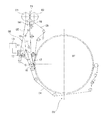
- the only drawing shows a schematic section through a conveyor unit.
- the feed unit is connected to a knife cylinder 02 and a opposite groove cylinder 03 formed cutting unit arranged with one in an overlying superstructure, not shown in the drawing, with the help several rotating slitting knives cut into strands and one above the other laid material web 01, z. B. a paper web 01, cut into individual signatures becomes.
- the signatures therefore consist of a different number of sheets of paper lying on top of each other, which are not firmly held together and therefore on are open to all four sides.
- the route along which the signatures are conveyed in the conveyor unit can be in two sections are subdivided, a first section 08, in which the signatures between two endless belts 06; 05, here as the second or third endless belt 06; 05 referred to, transported compressed, and a second section 09, in which they between a first endless belt 04 and a cylinder 07, z. B. one Collection cylinder 07 of a rotary printing press, are transported.
- a lower deflecting roller 18 of the third endless belt 05 is about an axis 19 while maintaining the tension of the third endless belt 05 pivotally mounted and thus allows access to the tongue 17 to this exchange or wait.
- the collecting cylinder 07 is by a motor, not shown in the drawing driven.
- the first endless belt 04, the collecting cylinder in the second section 09 07 wraps around an angular range of approximately 180 °, the collecting cylinder 07 driven by friction. If signatures are promoted in the second section 09, these transmit the driving force from the collecting cylinder 07 to the first endless belt 04.
- the outside of the signatures facing away from the collecting cylinder 07 due to their greater distance from the center of rotation of the collecting cylinder 07 a slightly higher web speed than the outer surface of the collecting cylinder 07 itself, the speed difference being proportional to the thickness of the signatures.
- the speed of the first endless belt 04 therefore adapts with changing thickness of the signatures automatically.
- the second endless belt 06 and the third endless belt 05 are the same Speed via an intermediate wheel 11 together from a drive device 12, z. B. driven a frequency-controlled motor 12. So it can also during the Transports of the signatures in the first section 08 do not result in any shear.
- the speed of the motor 12 is regulated by a control device 13, the task of which it is the path speeds of the two endless belts 05; 06 on a suitable, value adapted to the transport speed of the signatures in section 09 and thus to avoid that the sheets of the signatures during their transition from first section 08 in the second section 09 moved against each other or be compressed, and the signatures become unsightly or unusable.
- a first possibility to determine the web speeds of the three endless belts 04; 05; 06 to is to control the speed of the second and third endless belts 06 and 05 respectively of the first endless belt 04, so that a signature from the first Section 08 is passed into the second section 09 of the conveyor line, at least to their stretching side facing the third and first endless belts 05 and 04, respectively Is subjected to upsetting stress.
- the speed of the first endless belt 04 on the speed of the collecting cylinder 07 and the The thickness of the signatures to be funded is an active regulation of the Speed required for the various endless belts.
- the control device 13 for this purpose, the control device 13 according to a first embodiment of the Invention with two speed sensors for the web speed of the third and the second endless belt 05 and 06 connected and acts on an adjustment of these path speeds.
- the speed sensors can e.g. B. Angle of rotation encoder, each on a deflection roller 14 or 16 of the third or second endless belt 05; 06 and which are arranged every time the deflection roller 14; 16 has traveled a fixed angle of rotation, a pulse to the Deliver control device 13.
- These angle of rotation sensors are preferably identical in construction and are on deflection rollers 14; 16 mounted with the same radius.
- the Control device 13 an identical path speed of the endless belts 05; 06 thereby ensuring that they are constant, preferably disappearing Maintains phase offset between the pulses provided by the two sensors.
- the speed of the second and third endless belt 06; 05 is then proportional to the speed of the collecting cylinder 07, the proportionality factor being determined by the thickness of the between the collecting cylinder 07 and the first endless belt 04 funded signatures is determined.
- Another way of regulating the speed of the second endless belt 06 is the control device 13 on the one hand with a sensor for the speed of the first Endless belt 04 or the speed of rotation of the collecting cylinder 07 and on the other hand with a sensor for the thickness of the signatures to be transported connect, the control device 13 then a motor 12 to be observed Speed from the measured speed, corrected by one of the measured thickness dependent proportionality factor, calculated.
- a sensor for that Thickness of the signatures, or a size proportional to them, can vary greatly anywhere in the conveyor unit itself or better before the start of the Conveyor unit can be arranged on the material web 01.
- the intermediate wheel 11, which is the two Endless belts 05; 06 drives together via a gear (not shown) fixed translation coupled to the rotation of the collecting cylinder 07.
- the translation The gear is selected so that the path speed of the two endless belts 05; 06 is equal to the peripheral speed of the collecting cylinder 07.
- the third endless belt 05 runs slightly slower than the first Endless belt 04, which is then arranged in the conveyor line.
- the peripheral speed of the collecting cylinder 07 is a signature at the transition from Section 08 to section 09 at least on the second endless belt 06 and the Collective cylinder 07 facing side not exposed to any stretching or compression forces.
- a slight stretching stress can be on the opposite side of the Substrate in contact with the endless belts 05; 04 occur because the endless belt 04 itself moves slightly faster than the endless belt 05.
- the conveyor speed of the endless belts 05; 06 of the first Section 08 can in principle be set to any speed between the peripheral speed of the collecting cylinder 07 and the path speed of the first endless belt 04 lies. If you choose z. B. as the path speed of the first Section 08 the average of the peripheral speed of the collecting cylinder 07 and Path speed of the endless belt 04 acts on the collecting cylinder 07 facing surface of the signature when transferring to the second section 09 a slight compression, while the opposite, the endless belts 05, 04 facing surface of the signature is stretched.
Landscapes
- Engineering & Computer Science (AREA)
- Mechanical Engineering (AREA)
- Delivering By Means Of Belts And Rollers (AREA)
- Separation, Sorting, Adjustment, Or Bending Of Sheets To Be Conveyed (AREA)
- Attitude Control For Articles On Conveyors (AREA)
- Belt Conveyors (AREA)
- Folding Of Thin Sheet-Like Materials, Special Discharging Devices, And Others (AREA)
- Exhaust Gas After Treatment (AREA)
- Valve-Gear Or Valve Arrangements (AREA)
- Lubrication Details And Ventilation Of Internal Combustion Engines (AREA)
- Structure Of Belt Conveyors (AREA)
Abstract
Description
An einem solchen Regler kann eine Bedienungsperson auch nachträgliche Korrekturen vornehmen, wenn sie erkennt, dass die von der Fördereinheit geförderten Signaturen geschert sind.
- 01
- Materialbahn, Papierbahn
- 02
- Messerzylinder
- 03
- Nutenzylinder
- 04
- Endlosband, erstes
- 05
- Endlosband, drittes
- 06
- Endlosband, zweites
- 07
- Zylinder, Sammelzylinder
- 08
- Abschnitt, erster
- 09
- Abschnitt, zweiter
- 10
- -
- 11
- Zwischenrad
- 12
- Antriebseinrichtung, Motor
- 13
- Regeleinrichtung
- 14
- Umlenkwalze
- 15
- -
- 16
- Umlenkwalze
- 17
- Zunge
- 18
- Umlenkwalze
- 19
- Achse
Claims (16)
- Fördereinheit eines Falzapparates zum Fördern flacher Gegenstände mit wenigstens einem ersten und einem zweiten Endlosband (04; 06) und einem als Sammelzylinder (07) ausgebildeten Zylinder (07), wobei die Fördereinheit einer Schneideinrichtung nachgeordnet ist, wobei eine Förderstrecke für die Gegenstände einerseits wenigstens von dem ersten Endlosband (04) und andererseits von einem Teil des Umfangs des Zylinders (07) und dem zweiten Endlosband (06) begrenzt ist, wobei sich das erste Endlosband (04) entlang des Teils des Umfangs des Zylinders (07) erstreckt und die Förderstrecke gegenüber dem zweiten Endlosband (06) von einem dritten Endlosband (05) begrenzt ist, dadurch gekennzeichnet, dass eine von der Drehgeschwindigkeit des Zylinders (07) unabhängig regelbare Antriebseinrichtung (12) für das zweite und das dritte Endlosband (06; 05) angeordnet ist.
- Fördereinheit eines Falzapparates zum Fördern flacher Gegenstände mit wenigstens einem ersten und einem zweiten Endlosband (04; 06) und einem als Sammelzylinder (07) ausgebildeten Zylinder (07), wobei die Fördereinheit einer Schneideinrichtung nachgeordnet ist, wobei eine Förderstrecke für die Gegenstände einerseits wenigstens von dem ersten Endlosband (04) und andererseits von einem Teil des Umfangs des Zylinders (07) und dem zweiten Endlosband (06) begrenzt ist, wobei sich das erste Endlosband (04) entlang des Teils des Umfangs des Zylinders (07) erstreckt und die Förderstrecke gegenüber dem zweiten Endlosband (06) von einem dritten Endlosband (05) begrenzt ist, dadurch gekennzeichnet, dass das zweite und das dritte Endlosband (06; 05) durch ein Übersetzungsgetriebe an den Zylinder (07) gekoppelt sind, wobei das Übersetzungsverhältnis des Übersetzungsgetriebes so festgelegt ist, dass die Geschwindigkeit des zweiten und dritten Endlosbandes (06; 05) gleich der Umfangsgeschwindigkeit des Zylinders (07) ist.
- Fördereinheit nach Anspruch 1 oder 2, dadurch gekennzeichnet, dass das dritte Endlosband (05) an das zweite Endlosband (06) gekoppelt bewegt ist.
- Fördereinheit nach Anspruch 1, dadurch gekennzeichnet, dass das dritte Endlosband (05) mit der gleichen Geschwindigkeit wie das zweite Endlosband (06) antreibbar ist.
- Fördereinheit nach Anspruch 1, dadurch gekennzeichnet, dass eine Regeleinrichtung (13) angeordnet ist, die auf eine Angleichung der Geschwindigkeit des zweiten und dritten Endlosbandes (06; 05) an die Geschwindigkeit des ersten Endlosbandes (04) oder die Umfangsgeschwindigkeit des Zylinders (07) oder einen dazwischen liegenden Geschwindigkeitswert hinwirkt.
- Fördereinheit nach Anspruch 5, dadurch gekennzeichnet, dass die Regeleinrichtung die Geschwindigkeit des zweiten und dritten Endlosbandes (06; 05) mit einem variierbaren Proportionalitätsfaktor proportional zur Drehgeschwindigkeit des Zylinders (07) regelt.
- Fördereinheit nach Anspruch 5, dadurch gekennzeichnet, dass die Regeleinrichtung (13) an einen Sensor zum Messen der Geschwindigkeit des ersten Endlosbandes (04) gekoppelt ist.
- Fördereinheit nach Anspruch 5, dadurch gekennzeichnet, dass die Regeleinrichtung (13) an einen Sensor zum Erfassen einer Dicke der geförderten Gegenstände gekoppelt ist.
- Fördereinheit nach Anspruch 8, dadurch gekennzeichnet, dass der Sensor in Förderrichtung vor der Förderstrecke angeordnet ist.
- Fördereinheit nach Anspruch 1 oder 2, dadurch gekennzeichnet, dass das erste Endlosband (04) durch Reibkontakt mit dem Zylinder (07) angetrieben ist.
- Fördereinheit nach Anspruch 1, dadurch gekennzeichnet, dass die Antriebseinrichtung (12) einen frequenzgeregelten Motor (12) umfasst.
- Fördereinheit nach Anspruch 1 oder 2, dadurch gekennzeichnet, dass das zweite Endlosband (06) und das dritte Endlosband (05) mit gleicher Geschwindigkeit über ein Zwischenrad (11) gemeinsam von der Antriebseinrichtung (12) angetrieben sind.
- Fördereinheit nach Anspruch 1 oder 2, dadurch gekennzeichnet, dass das zweite Endlosband (06) und das dritte Endlosband (05) den Sammelzylinder (07) nicht berühren.
- Fördereinheit nach Anspruch 1 oder 2, dadurch gekennzeichnet, dass ein Anfang der Förderstrecke des ersten Endlosbandes (04) sich an ein Ende der Förderstrecke des dritten Endlosbandes (06) anschließt.
- Fördereinheit nach Anspruch 1 oder 2, dadurch gekennzeichnet, dass eine letzte Umlenkrolle (18) des dritten Endlosbandes (06) direkt benachbart zu einer ersten, zu der Umlenkrolle des dritten Endlosbandes (06) verschiedenen, Umlenkrolle des ersten Endlosbandes (04) angeordnet ist.
- Fördereinheit nach Anspruch 1 oder 2, dadurch gekennzeichnet, dass das erste Endlosband (04) Signaturen ausschließlich am Sammelzylinder transportierend angeordnet ist.
Applications Claiming Priority (3)
| Application Number | Priority Date | Filing Date | Title |
|---|---|---|---|
| DE10160754A DE10160754C2 (de) | 2001-11-14 | 2001-11-14 | Fördereinheit zum Fördern flacher Gegenstände |
| DE10160754 | 2001-11-14 | ||
| EP02776869A EP1446344B8 (de) | 2001-11-14 | 2002-11-06 | Fördereinheit für flache gegenstände |
Related Parent Applications (1)
| Application Number | Title | Priority Date | Filing Date |
|---|---|---|---|
| EP02776869A Division EP1446344B8 (de) | 2001-11-14 | 2002-11-06 | Fördereinheit für flache gegenstände |
Publications (1)
| Publication Number | Publication Date |
|---|---|
| EP1479630A1 true EP1479630A1 (de) | 2004-11-24 |
Family
ID=7708761
Family Applications (2)
| Application Number | Title | Priority Date | Filing Date |
|---|---|---|---|
| EP04101665A Withdrawn EP1479630A1 (de) | 2001-11-14 | 2002-11-06 | Fördereinheit für flache Gegenstände |
| EP02776869A Expired - Lifetime EP1446344B8 (de) | 2001-11-14 | 2002-11-06 | Fördereinheit für flache gegenstände |
Family Applications After (1)
| Application Number | Title | Priority Date | Filing Date |
|---|---|---|---|
| EP02776869A Expired - Lifetime EP1446344B8 (de) | 2001-11-14 | 2002-11-06 | Fördereinheit für flache gegenstände |
Country Status (8)
| Country | Link |
|---|---|
| US (3) | US7007603B2 (de) |
| EP (2) | EP1479630A1 (de) |
| CN (1) | CN1302972C (de) |
| AT (1) | ATE348775T1 (de) |
| AU (1) | AU2002339388A1 (de) |
| DE (2) | DE10160754C2 (de) |
| ES (1) | ES2275920T3 (de) |
| WO (1) | WO2003045826A1 (de) |
Families Citing this family (2)
| Publication number | Priority date | Publication date | Assignee | Title |
|---|---|---|---|---|
| US8210103B2 (en) | 2008-05-23 | 2012-07-03 | Goss International Americas, Inc. | Apparatus and method for supplying ribbons to a former |
| US8991694B2 (en) * | 2011-12-21 | 2015-03-31 | Ncr Corporation | Item removal |
Citations (5)
| Publication number | Priority date | Publication date | Assignee | Title |
|---|---|---|---|---|
| US3363520A (en) * | 1965-10-21 | 1968-01-16 | West Virginia Pulp & Paper Co | Means for collecting and transferring sheet material |
| US4094499A (en) * | 1975-11-06 | 1978-06-13 | Maschinenfabrik Goebel Gmbh | Device for controlling the actuation of gripping means in a sheet assembling apparatus |
| EP0205143A2 (de) * | 1985-06-14 | 1986-12-17 | OFFICINE MECCANICHE GIOVANNI CERUTTI S.p.A. | Vorrichtung zum kontinuierlichen Herstellen einer Zeitschrift, die einen Aussenumschlag aus staerkerem Papier aufweist |
| US5230268A (en) * | 1991-06-22 | 1993-07-27 | Man Roland Druckmaschinen Ag | Device for cross cutting and/or perforating of a web |
| DE9417127U1 (de) * | 1994-10-25 | 1994-12-22 | Maschinenfabrik Goebel Gmbh, 64293 Darmstadt | Einrichtung zum Verarbeiten von Material |
Family Cites Families (8)
| Publication number | Priority date | Publication date | Assignee | Title |
|---|---|---|---|---|
| US2278188A (en) * | 1940-08-03 | 1942-03-31 | Interchem Corp | Method of and apparatus for delivering sheets |
| US2788738A (en) * | 1950-08-03 | 1957-04-16 | Robert W Wood | Printing press for printing newspapers and the like |
| NL137201C (de) | 1965-05-27 | |||
| DE3321811C2 (de) * | 1983-06-16 | 1986-01-02 | M.A.N.- Roland Druckmaschinen AG, 6050 Offenbach | Falzapparat für Rollenrotationsdruckmaschinen |
| EP0575711A1 (de) | 1992-05-27 | 1993-12-29 | Mars, Incorporated | Kurzzeitspeicher für Banknoten |
| US5735516A (en) * | 1992-05-27 | 1998-04-07 | Mars Incorporated | Apparatus for handling sheets |
| DE4241810C2 (de) * | 1992-12-11 | 2001-01-04 | Heidelberger Druckmasch Ag | Formatvariabler Kombinationsfalzapparat |
| DE10107368A1 (de) * | 2001-02-16 | 2002-08-29 | Heidelberger Druckmasch Ag | Vorrichtung zum Führen flächiger Exemplare in Falzapparaten |
-
2001
- 2001-11-14 DE DE10160754A patent/DE10160754C2/de not_active Expired - Fee Related
-
2002
- 2002-11-06 CN CNB028223810A patent/CN1302972C/zh not_active Expired - Fee Related
- 2002-11-06 AU AU2002339388A patent/AU2002339388A1/en not_active Abandoned
- 2002-11-06 EP EP04101665A patent/EP1479630A1/de not_active Withdrawn
- 2002-11-06 WO PCT/DE2002/004106 patent/WO2003045826A1/de not_active Ceased
- 2002-11-06 US US10/494,045 patent/US7007603B2/en not_active Expired - Fee Related
- 2002-11-06 DE DE50209034T patent/DE50209034D1/de not_active Expired - Fee Related
- 2002-11-06 AT AT02776869T patent/ATE348775T1/de not_active IP Right Cessation
- 2002-11-06 ES ES02776869T patent/ES2275920T3/es not_active Expired - Lifetime
- 2002-11-06 EP EP02776869A patent/EP1446344B8/de not_active Expired - Lifetime
-
2005
- 2005-09-09 US US11/221,881 patent/US7191704B2/en not_active Expired - Fee Related
- 2005-09-09 US US11/221,880 patent/US7134392B2/en not_active Expired - Fee Related
Patent Citations (5)
| Publication number | Priority date | Publication date | Assignee | Title |
|---|---|---|---|---|
| US3363520A (en) * | 1965-10-21 | 1968-01-16 | West Virginia Pulp & Paper Co | Means for collecting and transferring sheet material |
| US4094499A (en) * | 1975-11-06 | 1978-06-13 | Maschinenfabrik Goebel Gmbh | Device for controlling the actuation of gripping means in a sheet assembling apparatus |
| EP0205143A2 (de) * | 1985-06-14 | 1986-12-17 | OFFICINE MECCANICHE GIOVANNI CERUTTI S.p.A. | Vorrichtung zum kontinuierlichen Herstellen einer Zeitschrift, die einen Aussenumschlag aus staerkerem Papier aufweist |
| US5230268A (en) * | 1991-06-22 | 1993-07-27 | Man Roland Druckmaschinen Ag | Device for cross cutting and/or perforating of a web |
| DE9417127U1 (de) * | 1994-10-25 | 1994-12-22 | Maschinenfabrik Goebel Gmbh, 64293 Darmstadt | Einrichtung zum Verarbeiten von Material |
Also Published As
| Publication number | Publication date |
|---|---|
| US20060065141A1 (en) | 2006-03-30 |
| US7007603B2 (en) | 2006-03-07 |
| WO2003045826A1 (de) | 2003-06-05 |
| ES2275920T3 (es) | 2007-06-16 |
| US20050017425A1 (en) | 2005-01-27 |
| US20060065140A1 (en) | 2006-03-30 |
| DE10160754A1 (de) | 2003-05-22 |
| EP1446344B8 (de) | 2007-03-14 |
| AU2002339388A1 (en) | 2003-06-10 |
| US7134392B2 (en) | 2006-11-14 |
| DE50209034D1 (de) | 2007-02-01 |
| US7191704B2 (en) | 2007-03-20 |
| EP1446344B1 (de) | 2006-12-20 |
| ATE348775T1 (de) | 2007-01-15 |
| CN1585720A (zh) | 2005-02-23 |
| EP1446344A1 (de) | 2004-08-18 |
| CN1302972C (zh) | 2007-03-07 |
| DE10160754C2 (de) | 2003-10-09 |
Similar Documents
| Publication | Publication Date | Title |
|---|---|---|
| DE69126911T2 (de) | Doppelte Zusammentragmaschine | |
| EP2164784B1 (de) | Ausrichten von lebensmittelprodukten | |
| EP2874888B1 (de) | Produktstapelvorrichtung | |
| EP0498068B1 (de) | Falzapparat, bei dem der Transport der Falzexemplare über Transportmittel, Bandrollen und Bänder erfolgt | |
| EP1686084B1 (de) | Einrichtung zum Zusammentragen von Druckbogen an einer Förderstrecke einer umlaufenden Fördervorrichtung | |
| DE3345191A1 (de) | Vorrichtung zum aufwickeln eines schuppenstroms aus papierbogen | |
| EP0658426B1 (de) | Falzapparat | |
| DE3816690C2 (de) | ||
| DE4345160C2 (de) | Vorrichtung zur Richtungsumkehr von flachen Sendungen | |
| DE10160754C2 (de) | Fördereinheit zum Fördern flacher Gegenstände | |
| EP2055660B1 (de) | Vorrichtung zum getakteten Umlenken von flächigen Gegenständen | |
| DE69504244T2 (de) | Verfahren zum gegenseitigen Repositionieren von Produkten, zum Beispiel zum Einstellen von der gegenseitigen Position von graphischen Produkten in einer Verpackungsvorrichtung, und eine Zufuhrvorrichtung zum Ausführen des Verfahren | |
| EP2583924A2 (de) | Bogenbearbeitungsmaschine mit Bogenanleger mit Saugbandmodul | |
| DE3812685C2 (de) | Verzögerungs-Vorrichtung für Bogenlagen | |
| EP1365983B1 (de) | Fördereinheit für flache gegenstände | |
| EP0908310A2 (de) | Bahnstrangantrieb oberhalb eines Falzapparates | |
| EP1504922B1 (de) | Ueberführungseinrichtung mit Dickenmessung eines Buchblocks | |
| EP2746204B1 (de) | Vorrichtung und Verfahren zum Drehen von flachen Gütern | |
| EP2583922A2 (de) | Bandanleger mit abklappbarer Vereinzelungsanordnung | |
| DE3744107C2 (de) | ||
| EP1110894B1 (de) | Verfahren und Vorrichtung zum Falzen von Materialbogen | |
| EP0852989A2 (de) | Vorrichtung und Verfahren zur Bereitstellung insbesondere eines Ladeträgers für Packungseinheiten | |
| WO1999035072A1 (de) | Vorrichtung zum verändern der lage von in einem schuppenstrom geförderten gegenständen | |
| DE4238386C1 (de) | Einrichtung zum Querschneiden kontinuierlich zugeführten Materials | |
| EP0916608B1 (de) | Falzbogenfördervorrichtung, insbesondere für Sammelhefter |
Legal Events
| Date | Code | Title | Description |
|---|---|---|---|
| PUAI | Public reference made under article 153(3) epc to a published international application that has entered the european phase |
Free format text: ORIGINAL CODE: 0009012 |
|
| AC | Divisional application: reference to earlier application |
Ref document number: 1446344 Country of ref document: EP Kind code of ref document: P |
|
| AK | Designated contracting states |
Kind code of ref document: A1 Designated state(s): AT BE BG CH CY CZ DE DK EE ES FI FR GB GR IE IT LI LU MC NL PT SE SK TR |
|
| AX | Request for extension of the european patent |
Extension state: AL LT LV MK |
|
| 17P | Request for examination filed |
Effective date: 20041020 |
|
| AKX | Designation fees paid |
Designated state(s): AT BE BG CH CY CZ DE DK EE ES FI FR GB GR IE IT LI LU MC NL PT SE SK TR |
|
| 17Q | First examination report despatched |
Effective date: 20060918 |
|
| STAA | Information on the status of an ep patent application or granted ep patent |
Free format text: STATUS: THE APPLICATION HAS BEEN WITHDRAWN |
|
| 18W | Application withdrawn |
Effective date: 20090220 |