EP1477666A1 - Pompe d'alimentation, en particulier pompe à combustible à haute pression pour moteurs à combustion interne - Google Patents
Pompe d'alimentation, en particulier pompe à combustible à haute pression pour moteurs à combustion interne Download PDFInfo
- Publication number
- EP1477666A1 EP1477666A1 EP04005089A EP04005089A EP1477666A1 EP 1477666 A1 EP1477666 A1 EP 1477666A1 EP 04005089 A EP04005089 A EP 04005089A EP 04005089 A EP04005089 A EP 04005089A EP 1477666 A1 EP1477666 A1 EP 1477666A1
- Authority
- EP
- European Patent Office
- Prior art keywords
- feed pump
- pump
- actuating device
- actuating
- actuator
- Prior art date
- Legal status (The legal status is an assumption and is not a legal conclusion. Google has not performed a legal analysis and makes no representation as to the accuracy of the status listed.)
- Granted
Links
Images


Classifications
-
- F—MECHANICAL ENGINEERING; LIGHTING; HEATING; WEAPONS; BLASTING
- F02—COMBUSTION ENGINES; HOT-GAS OR COMBUSTION-PRODUCT ENGINE PLANTS
- F02M—SUPPLYING COMBUSTION ENGINES IN GENERAL WITH COMBUSTIBLE MIXTURES OR CONSTITUENTS THEREOF
- F02M63/00—Other fuel-injection apparatus having pertinent characteristics not provided for in groups F02M39/00 - F02M57/00 or F02M67/00; Details, component parts, or accessories of fuel-injection apparatus, not provided for in, or of interest apart from, the apparatus of groups F02M39/00 - F02M61/00 or F02M67/00; Combination of fuel pump with other devices, e.g. lubricating oil pump
- F02M63/0012—Valves
- F02M63/0031—Valves characterized by the type of valves, e.g. special valve member details, valve seat details, valve housing details
-
- F—MECHANICAL ENGINEERING; LIGHTING; HEATING; WEAPONS; BLASTING
- F02—COMBUSTION ENGINES; HOT-GAS OR COMBUSTION-PRODUCT ENGINE PLANTS
- F02M—SUPPLYING COMBUSTION ENGINES IN GENERAL WITH COMBUSTIBLE MIXTURES OR CONSTITUENTS THEREOF
- F02M59/00—Pumps specially adapted for fuel-injection and not provided for in groups F02M39/00 -F02M57/00, e.g. rotary cylinder-block type of pumps
- F02M59/20—Varying fuel delivery in quantity or timing
- F02M59/36—Varying fuel delivery in quantity or timing by variably-timed valves controlling fuel passages to pumping elements or overflow passages
- F02M59/366—Valves being actuated electrically
- F02M59/367—Pump inlet valves of the check valve type being open when actuated
-
- F—MECHANICAL ENGINEERING; LIGHTING; HEATING; WEAPONS; BLASTING
- F02—COMBUSTION ENGINES; HOT-GAS OR COMBUSTION-PRODUCT ENGINE PLANTS
- F02M—SUPPLYING COMBUSTION ENGINES IN GENERAL WITH COMBUSTIBLE MIXTURES OR CONSTITUENTS THEREOF
- F02M63/00—Other fuel-injection apparatus having pertinent characteristics not provided for in groups F02M39/00 - F02M57/00 or F02M67/00; Details, component parts, or accessories of fuel-injection apparatus, not provided for in, or of interest apart from, the apparatus of groups F02M39/00 - F02M61/00 or F02M67/00; Combination of fuel pump with other devices, e.g. lubricating oil pump
- F02M63/0012—Valves
- F02M63/0014—Valves characterised by the valve actuating means
- F02M63/0015—Valves characterised by the valve actuating means electrical, e.g. using solenoid
-
- F—MECHANICAL ENGINEERING; LIGHTING; HEATING; WEAPONS; BLASTING
- F02—COMBUSTION ENGINES; HOT-GAS OR COMBUSTION-PRODUCT ENGINE PLANTS
- F02M—SUPPLYING COMBUSTION ENGINES IN GENERAL WITH COMBUSTIBLE MIXTURES OR CONSTITUENTS THEREOF
- F02M63/00—Other fuel-injection apparatus having pertinent characteristics not provided for in groups F02M39/00 - F02M57/00 or F02M67/00; Details, component parts, or accessories of fuel-injection apparatus, not provided for in, or of interest apart from, the apparatus of groups F02M39/00 - F02M61/00 or F02M67/00; Combination of fuel pump with other devices, e.g. lubricating oil pump
- F02M63/0012—Valves
- F02M63/0031—Valves characterized by the type of valves, e.g. special valve member details, valve seat details, valve housing details
- F02M63/004—Sliding valves, e.g. spool valves, i.e. whereby the closing member has a sliding movement along a seat for opening and closing
-
- F—MECHANICAL ENGINEERING; LIGHTING; HEATING; WEAPONS; BLASTING
- F02—COMBUSTION ENGINES; HOT-GAS OR COMBUSTION-PRODUCT ENGINE PLANTS
- F02M—SUPPLYING COMBUSTION ENGINES IN GENERAL WITH COMBUSTIBLE MIXTURES OR CONSTITUENTS THEREOF
- F02M63/00—Other fuel-injection apparatus having pertinent characteristics not provided for in groups F02M39/00 - F02M57/00 or F02M67/00; Details, component parts, or accessories of fuel-injection apparatus, not provided for in, or of interest apart from, the apparatus of groups F02M39/00 - F02M61/00 or F02M67/00; Combination of fuel pump with other devices, e.g. lubricating oil pump
- F02M63/0012—Valves
- F02M63/0031—Valves characterized by the type of valves, e.g. special valve member details, valve seat details, valve housing details
- F02M63/0043—Two-way valves
-
- F—MECHANICAL ENGINEERING; LIGHTING; HEATING; WEAPONS; BLASTING
- F02—COMBUSTION ENGINES; HOT-GAS OR COMBUSTION-PRODUCT ENGINE PLANTS
- F02M—SUPPLYING COMBUSTION ENGINES IN GENERAL WITH COMBUSTIBLE MIXTURES OR CONSTITUENTS THEREOF
- F02M63/00—Other fuel-injection apparatus having pertinent characteristics not provided for in groups F02M39/00 - F02M57/00 or F02M67/00; Details, component parts, or accessories of fuel-injection apparatus, not provided for in, or of interest apart from, the apparatus of groups F02M39/00 - F02M61/00 or F02M67/00; Combination of fuel pump with other devices, e.g. lubricating oil pump
- F02M63/02—Fuel-injection apparatus having several injectors fed by a common pumping element, or having several pumping elements feeding a common injector; Fuel-injection apparatus having provisions for cutting-out pumps, pumping elements, or injectors; Fuel-injection apparatus having provisions for variably interconnecting pumping elements and injectors alternatively
- F02M63/0225—Fuel-injection apparatus having a common rail feeding several injectors ; Means for varying pressure in common rails; Pumps feeding common rails
-
- F—MECHANICAL ENGINEERING; LIGHTING; HEATING; WEAPONS; BLASTING
- F04—POSITIVE - DISPLACEMENT MACHINES FOR LIQUIDS; PUMPS FOR LIQUIDS OR ELASTIC FLUIDS
- F04B—POSITIVE-DISPLACEMENT MACHINES FOR LIQUIDS; PUMPS
- F04B49/00—Control, e.g. of pump delivery, or pump pressure of, or safety measures for, machines, pumps, or pumping installations, not otherwise provided for, or of interest apart from, groups F04B1/00 - F04B47/00
- F04B49/22—Control, e.g. of pump delivery, or pump pressure of, or safety measures for, machines, pumps, or pumping installations, not otherwise provided for, or of interest apart from, groups F04B1/00 - F04B47/00 by means of valves
- F04B49/24—Bypassing
- F04B49/243—Bypassing by keeping open the inlet valve
Definitions
- the invention relates to a feed pump, in particular High-pressure fuel pump for an internal combustion engine, with a pump housing and an electromagnetic Actuation device, with the help of which of the Delivery pump funded amount of fluid can be adjusted.
- Such a feed pump is known from DE 199 38 504 A1 known.
- This is a single-cylinder high-pressure pump for high pressure supply in common rail injection systems of internal combustion engines.
- a electromagnetic actuator may be Inlet valve of the feed pump even during a Conveyor stroke of a piston of the feed pump forcibly be kept open.
- a valve element of Inlet valve of a plunger of the actuator applied.
- the actuator itself is in encapsulated in a separate housing.
- the object of the present invention is a delivery pump of the type mentioned in such a way that they produced cheaper and with her even at high Speeds of the pump, the pumped amount of fluid can be adjusted precisely.
- This object is in a feed pump the above mentioned type solved by the Actuator integrated into the pump housing so is that a magnetic circuit of the actuator at least through a region of the pump housing is closed.
- a first advantage of the feed pump according to the invention is that it can be produced inexpensively, as for the production of the actuator comparatively low material usage is required.
- the reason for this is the fact that according to the invention a Part of the magnetic flux, which for the electromagnetic Actuation of the actuator must be generated, not in the actuator itself, but in the actuator Housing of the feed pump is performed.
- the feed pump according to the invention builds smaller and can therefore be easier for example in an internal combustion engine are installed.
- the Actuating a bracket element from a comprises magnetic material which is arranged and connected to the pump housing so that it is for Conclusion of the magnetic circuit at least contributes.
- This Training is inexpensive and easy to manufacture.
- the actuating device on the pump housing facing side of a Magnetic anchor a connection element for connection to the pump housing and on the pump housing opposite side of the armature an armature counter element having, wherein the connecting element and the Anchor counter element via a sleeve member of a non-magnetic or dielectric material connected to each other.
- the Magnetic anchor optimally integrated in the magnetic circuit.
- the Connecting element with the sleeve element, and the Sleeve member welded to the armature counter-element, and all three elements at least part of a pre-assembled hydraulic assembly are.
- the welding is good fluid tightness and pre-assembly overall facilitates the assembly of the invention Feed pump.
- the connecting element with the pump housing is welded. This also makes a good Fluid tightness of the system achieved.
- the elements each first be joined together with a press connection. It is also advantageous if the Connecting element is positioned so that a certain opening stroke of the intake valve is set, which results when the actuator at the stop is applied.
- Anchor counter element at least indirectly a stop for forms an actuating element of the actuating device and connected to the dielectric sleeve to size, such that thereby the one end position of the Beetzrienselements is set.
- a precise Setting an end position of the actuating element creates reproducible conditions and increases precision the adjustment of the flow rate of the feed pump.
- the temperature influence on the Switching time of the actuator can be minimized. This is related to the fact that the specific resistance of brass depends less on the temperature than for example, that of copper.
- Another particularly advantageous embodiment of according to the invention is characterized that an actuator of the actuator to a valve element of the feed pump attacks in one place, which is off-center with respect to the valve element.
- an actuator of the actuator to a valve element of the feed pump attacks in one place, which is off-center with respect to the valve element.
- the for an actuation of the valve element force to be applied by the actuator reduced.
- the Actuator raises the valve element due of the off-center attack in an imbalance, in which It is not only the actuator of the Actuator, but also for example a housing-side area supported. Share this the holding forces on the one hand on this housing side Range and on the other on the actuator on.
- the actuator can be made smaller which ultimately results in shorter switching times Has.
- a realization of such an off-center Attack point may be that the longitudinal axis of Actuator against a plane of the Valve element is at an angle not equal to 90 °.
- the Longitudinal axis of the actuating element relative to the center of the Valve element is arranged offset. Both are easy to realize.
- the fluid connection at least one preferably spiral groove in the lateral surface of the magnet armature include.
- a spiral groove is the Symmetry of the armature not or at least not significantly influenced.
- Feed pump provides that the actuating device a having first stop element on which the of a Inlet valve of the pump facing away from the end of a Actuator of the actuator in his Movement comes into contact, and that by means of a Spot welding is attached. This again increases the Precision in the positioning of the end position of the Actuator, as for the stop element Material selected with correspondingly optimal properties can be. To absorb impact forces is a easy to apply spot welding for fixation sufficient.
- the actuating device can also be a second Include stop element, which in a guide of a Actuating element of the actuator integrated is and the stroke of the actuator to a Inlet valve of the delivery pump limited. Thus, without Significant additional effort also this final position of the Actuator can be adjusted precisely.
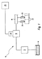
- an internal combustion engine carries the total Reference numeral 10. It comprises a prefeed pump 12, which the fuel from a container 14 to a Promotes high pressure pump 16 out. This compresses the Fuel to a very high pressure and promotes it too a fuel manifold 18 in which the fuel stored under high pressure. To the fuel manifold 18 are multiple fuel injectors 20 connected to the fuel inject combustion chambers 22 assigned directly to them.
- the high-pressure pump 16 is not on in Figure 1 shown way directly from a camshaft of the Internal combustion engine 10 driven. It is, as will be explained below, to a single-cylinder piston pump.
- For adjusting the flow rate of High pressure pump 16 is an electromagnetic to this Actuator 24 mounted, which of a Control and regulating device 26 is controlled.
- the high pressure pump 16 includes a pump housing 28 in which a delivery piston 30 is reciprocably received.
- the delivery piston 30 defines a delivery chamber 32, in the the fuel in a suction stroke of the delivery piston 30 via an inlet 34 and an inlet valve 36 passes.
- On Outlet channel 38 does not lead from the delivery chamber 32 to a illustrated exhaust valve and on to the fuel manifold 18.
- the inlet valve 36 is a spring-loaded check valve with a valve spring 40, a disc-shaped valve element 42 and a annular valve seat 44.
- the actuator 24 is in the embodiment shown in Figure 2 coaxial with a central axis 46 of the valve element 42 arranged. It comprises a hydraulic assembly 48 (See Figure 3) and an electrical assembly 50th (See Figure 4).
- the hydraulic assembly 48 comprises a tubular Connecting element 52 (see Figure 6), on the in Installation position facing away from the inlet valve 36 end Sleeve member 54 is pushed in a press fit.
- a Longitudinal bore 56 of the connecting element 52 is on the in Installation position the inlet valve 36 facing the end Guide ring 58 received in a press fit, in which a plunger-like actuator 60 is guided.
- the Actuator 60 extends over the two ends of the connecting element 52 addition.
- On his from Inlet valve 36 remote end portion is a cylindrical magnet armature 62 (see FIG. 5) pushed on and also fastened in a press fit.
- a spiral groove 63 is present, which from an end face of the armature 62 to opposite end leads.
- a compression spring 64 braced between the Magnetic armature 62 and the guide ring 58.
- the end remote from the connecting element 52 of the Sleeve member 54 is defined by a lid portion 66 locked.
- a disk-shaped stop member 68 is in Sleeve member 54 in close proximity to the lid portion 66th added.
- the actuator 60 is available with his from Inlet valve 36 projecting end slightly above the armature 62 out. Therefore, in the in Figs. 2 and 3 shown rest position the actuator 60 of the Pressed spring 64 against the stop member 68.
- in the Connecting element 52 are in its longitudinal direction extending holes 70 are present, which are the two End sides (without reference numeral) of the connecting element 52nd fluidly interconnect.
- the electrical assembly 50 (FIG. 4) comprises a Coil carrier 72 and a magnetic coil 74.
- the winding of the Magnetic coil 74 is made of brass.
- Coil carrier 72 and magnetic coil 74 are molded with plastic 76.
- the Integration of the electromagnetic actuator 24 in the high pressure pump 16 is as follows:
- the hydraulic assembly 48 is pre-assembled.
- the magnet armature 62 with the actuating element 60 joined, which then into the longitudinal bore 56 of the Connecting element 52 is introduced.
- the Compression spring 64 is pushed onto the actuator 60 and
- the guide ring 58 in the longitudinal bore 56th brought in.
- the stopper 68 in the sleeve member 54 is inserted and by a Spot weld 78 attached.
- the sleeve element becomes 54 so pushed to measure on the connecting element 52, that a desired possible stroke of the Actuator 60 results.
- Between the Connecting element 52 and the sleeve member 54 is a Press fit provided.
- the likewise preassembled electrical assembly 50 is now pushed onto the hydraulic assembly 48. Then is a bow-shaped fastener 88 on the electrical assembly 50 is pushed and with the Pump housing 28 welded (reference numeral 90).
- the Bow-shaped fastener 88 is made of a material manufactured, which has magnetic properties. The same applies to the pump housing 28. About the Connecting element 52, the armature 62, the bow-shaped Fastener 88 and the pump housing 28 is so in Operation a closed magnetic circuit 91 created (this is in the figure by a dot-dash line ) Indicated. For tolerance compensation and compensation of Thermal expansion is between the electrical assembly 50 and the pump housing 28, a spring element 92 braced.
- the high pressure pump 16 and the actuator 24 work as follows:
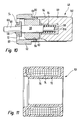
- FIG 7 is an alternative embodiment of a High pressure pump 16 shown. Thereby carry such elements and areas which are equivalent functions to elements and areas of those shown in Figures 2 to 6 Have high-pressure pump, the same reference numerals. she are not explained again in detail.
- the receiving opening 84 for the electromagnetic Actuator 24 is not coaxial with the central axis of Valve element 46, but with respect to this laterally to S added.
- the actuator 60 engages the Valve element 42 of the intake valve 36 off-center. at energized solenoid 74 thereby becomes the valve member 42 open at an angle, and it lies in the forced open Position on the one to the actuator 60 and the others on the annular valve seat 44.
- FIG. 8 Embodiment the same is shown in FIG. 8 Embodiment. Again, such elements and Areas that are functionally equivalent to elements and Areas of the illustrated in Figures 2 to 7 Embodiments bear the same reference numerals and not explained again in detail.
- the longitudinal axis of the Actuator 60 with respect to a plane in which the valve element 42 is in the closed state in an angle W, which is not equal to 90 °. Also by this becomes an off - center point of attack of the Actuator 60 on the valve element 42 of the Inlet valve 36 created.
- High pressure pumps 16 was the electromagnetic Actuator 24 designed so that when not energized solenoid 74, ie in the de-energized state, the Position of the valve element 42 of the inlet valve 36 of the electromagnetic actuator 24 is not was influenced.
- Such an electromagnetic Actuator 24 is also called “de-energized closed ".
- the actuator has 60 in contrast to the previous embodiments in the high-pressure pump 16 shown in FIG Central portion 96 with a larger diameter than his both end sections 98 and 100 respectively
- Inlet valve 36 remote from the magnet armature 62 is a cylindrical armature counterpart 102 is present, which is welded to the sleeve member 54.
- the from the Inlet valve 36 remote end 100 of the Actuator 60 is in a blind hole 104 of the Anchor counterpart 102 added, in which a cup-shaped stop member 68 is inserted.
- the magnetic coil 74 remains energized to achieve maximum delivery. If the delivery rate is to be reduced, the Magnetic coil 74 briefly de-energized. This will be the Actuator 60 by the compression spring 64 against the Force of the valve spring 40 and against the hydraulic force on the valve element 42 moves in the opening direction, whereby the Valve element 42 lifts off from the valve seat 44. As a stop in Opening direction acts while the guide ring 58, which in this case with one between the left End portion 98 and the central portion 96 of Actuator 60 formed paragraph (without Reference numerals) cooperates.
- the assembly of the hydraulic assembly 48 is carried out by that first of the guide ring 58 on the connecting element 52nd and then the sleeve member 54 on the connecting element 52 is attached. Then, the stopper 68 in Anchor counterpart 102 is pressed and the compression spring 64 in the stop member 68 inserted.
- the actuator 60 For adjusting the axial Restluftspalts between the armature 62 and the Anchor counterpart 102, the actuator 60 must together with the armature 62 on the one hand and the Anchor counterpart 102 with the associated with him Stopping part 68 on the other hand be paired.
- This pairing can, as can be seen from Figure 14, under Use of a spacer 106 made during the Assembly of the magnet armature 62 on the actuating element 60 between armature 62 and armature counterpart 102 placed becomes.
- the thickness of this spacer 106 then corresponds the residual air gap. It would also be possible, the distance between a stop surface (without reference numeral) of Stopper 68 and the corresponding surface of the Anchor counterpart 102 to measure and then the Magnetic armature 62 on the actuator 60 to measure put.
- the hydraulic assembly 48 is completed by the Anchor counterpart 102 with the actuator 60 and the Magnetic armature 62 inserted into the sleeve member 54 and with this is welded. It is used to set a desired strokes of the actuator 60 the Anchor counterpart 102 to measure in the sleeve member 54th inserted. Preferably, this is a press fit intended.
- the sleeve member 54 is on the one hand with the Connecting element 52 and on the other hand with the Anchor counterpart 102 in 80 tightly welded. Subsequently is the hydraulic assembly 48 in the corresponding Receiving opening 84 inserted in the pump housing 28 and 86th welded. Then, the electric assembly 50 becomes mounted and the bracket 88 welded in 90 and 105.
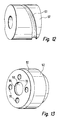
- FIGS. 15 and 16 of FIGS Figure 9 shown high pressure pump differ from this by the same characteristics by which the in Figures 7 and 8 embodiments of the differ in Figure 2 shown high-pressure pump 16.
- the above with regard to functionally equivalent Elements and areas apply accordingly.
Landscapes
- Engineering & Computer Science (AREA)
- Mechanical Engineering (AREA)
- General Engineering & Computer Science (AREA)
- Chemical & Material Sciences (AREA)
- Combustion & Propulsion (AREA)
- Fuel-Injection Apparatus (AREA)
- Magnetically Actuated Valves (AREA)
- Details Of Reciprocating Pumps (AREA)
Applications Claiming Priority (2)
| Application Number | Priority Date | Filing Date | Title |
|---|---|---|---|
| DE10320592 | 2003-05-08 | ||
| DE10320592A DE10320592A1 (de) | 2003-05-08 | 2003-05-08 | Förderpumpe, insbesondere Hochdruck-Kraftstoffpumpe für eine Brennkraftmaschine |
Publications (2)
| Publication Number | Publication Date |
|---|---|
| EP1477666A1 true EP1477666A1 (fr) | 2004-11-17 |
| EP1477666B1 EP1477666B1 (fr) | 2006-01-25 |
Family
ID=33016325
Family Applications (1)
| Application Number | Title | Priority Date | Filing Date |
|---|---|---|---|
| EP04005089A Expired - Lifetime EP1477666B1 (fr) | 2003-05-08 | 2004-03-04 | Pompe d'alimentation, en particulier pompe à combustible à haute pression pour moteurs à combustion interne |
Country Status (3)
| Country | Link |
|---|---|
| US (1) | US20040223856A1 (fr) |
| EP (1) | EP1477666B1 (fr) |
| DE (2) | DE10320592A1 (fr) |
Cited By (5)
| Publication number | Priority date | Publication date | Assignee | Title |
|---|---|---|---|---|
| WO2014206670A1 (fr) * | 2013-06-25 | 2014-12-31 | Robert Bosch Gmbh | Unité de dosage de carburant pour système d'injection à haute pression |
| WO2015106935A1 (fr) * | 2014-01-16 | 2015-07-23 | Robert Bosch Gmbh | Pompe à haute pression munie d'une soupape d'aspiration électromagnétique |
| EP3051117A1 (fr) * | 2015-01-28 | 2016-08-03 | Delphi Technologies, Inc. | Régulateur de pression de carburant |
| WO2017102144A1 (fr) * | 2015-12-17 | 2017-06-22 | Robert Bosch Gmbh | Soupape, notamment soupape d'aspiration, dans une pompe haute pression d'un système d'injection de carburant |
| WO2018073246A1 (fr) * | 2016-10-18 | 2018-04-26 | Robert Bosch Gmbh | Soupape d'admission à commande électromagnétique et pompe haute pression munie d'une soupape d'admission |
Families Citing this family (19)
| Publication number | Priority date | Publication date | Assignee | Title |
|---|---|---|---|---|
| DE102005051937A1 (de) * | 2005-10-29 | 2007-05-03 | Pierburg Gmbh | Schubumluftventilvorrichtung für eine Brennkraftmaschine |
| JP4701227B2 (ja) * | 2007-10-29 | 2011-06-15 | 日立オートモティブシステムズ株式会社 | プランジャ式高圧燃料ポンプ |
| EP2184494A3 (fr) * | 2008-11-05 | 2016-09-21 | Magna Powertrain Inc. | Assemblage de pompe à eau sous/hors tension sur demande |
| DE102009046088B4 (de) * | 2009-10-28 | 2021-07-29 | Robert Bosch Gmbh | Mengensteuerventil, insbesondere in einer Kraftstoff-Hochdruckpumpe, zur Zumessung eines fluiden Mediums |
| US8584441B2 (en) | 2010-01-05 | 2013-11-19 | Honeywell International Inc. | Fuel metering system electrically servoed metering pump |
| JP5331731B2 (ja) * | 2010-03-03 | 2013-10-30 | 日立オートモティブシステムズ株式会社 | 電磁式の流量制御弁及びそれを用いた高圧燃料供給ポンプ |
| DE102010062451A1 (de) * | 2010-12-06 | 2012-06-06 | Robert Bosch Gmbh | Schaltventil mit einem Ventilkörper und einer diesen wenigstens zeitweise in Öffnungsrichtung beaufschlagenden Ventilnadel |
| DE102011076784B4 (de) * | 2011-05-31 | 2015-07-30 | Continental Automotive Gmbh | Einlassventil für eine Fluidpumpe und Montageverfahren für ein Einlassventil für eine Fluidpumpe |
| DE102011090006B4 (de) * | 2011-12-28 | 2015-03-26 | Continental Automotive Gmbh | Ventil |
| JP5857878B2 (ja) * | 2012-05-17 | 2016-02-10 | 株式会社日本自動車部品総合研究所 | 電磁弁 |
| DE102012214920A1 (de) * | 2012-08-22 | 2014-02-27 | Continental Automotive Gmbh | Dämpfungsoberfläche an Ventilkomponenten |
| WO2014148367A1 (fr) * | 2013-03-22 | 2014-09-25 | サンデン株式会社 | Vanne de commande et compresseur à capacité variable pourvu de ladite vanne de commande |
| CN103195623B (zh) * | 2013-04-24 | 2015-02-11 | 中国重汽集团重庆燃油喷射系统有限公司 | 燃油泵总成 |
| DE102013220877A1 (de) * | 2013-10-15 | 2015-04-16 | Continental Automotive Gmbh | Ventil |
| DE102015221300A1 (de) * | 2015-10-30 | 2017-05-04 | Continental Automotive Gmbh | Ventil |
| DE102015224421A1 (de) * | 2015-12-07 | 2017-06-08 | Robert Bosch Gmbh | Elektromagnetisch betätigbares Einlassventil und Hochdruckpumpe mit Einlassventil |
| US10060380B2 (en) * | 2016-06-21 | 2018-08-28 | Denso International America, Inc. | Inter-connect circuit device for vehicle fuel delivery system |
| IT201700116427A1 (it) * | 2017-10-16 | 2019-04-16 | Bosch Gmbh Robert | Una valvola di dosaggio per un gruppo pompa di alimentazione di carburante ad un motore a combustione interna e gruppo pompa comprendente tale valvola |
| JP7115328B2 (ja) * | 2019-01-15 | 2022-08-09 | 株式会社デンソー | 電磁弁 |
Citations (6)
| Publication number | Priority date | Publication date | Assignee | Title |
|---|---|---|---|---|
| US4647008A (en) * | 1984-08-21 | 1987-03-03 | Toyota Jidosha Kabushiki Kaisha | Solenoid valve for hydraulic control |
| DE4313110A1 (de) * | 1993-04-03 | 1994-10-06 | Rexroth Mannesmann Gmbh | Pumpvorrichtung zur Brennstoffeinspritzung, insbesondere zur Dieselkraftstoffeinspritzung bei Kraftfahrzeugen |
| US5775301A (en) * | 1995-06-02 | 1998-07-07 | Ganser-Hydromag Ag | Fuel injection valve for internal combustion engines |
| DE19751240A1 (de) * | 1997-11-19 | 1999-05-20 | Itt Mfg Enterprises Inc | Elektromagnetventil |
| US6148796A (en) * | 1998-01-12 | 2000-11-21 | Robert Bosch Gmbh | Switching magnet for a high pressure pump |
| US20010048091A1 (en) * | 2000-07-28 | 2001-12-06 | Shigeiku Enomoto | Electromagnetic valve |
Family Cites Families (7)
| Publication number | Priority date | Publication date | Assignee | Title |
|---|---|---|---|---|
| DE3142750C2 (de) * | 1980-12-19 | 1984-06-20 | Nissan Motor Co., Ltd., Yokohama, Kanagawa | Treibstoffeinspritzpumpe für eine Diesel-Brennkraftmaschine |
| DE3632299A1 (de) * | 1986-09-23 | 1988-03-24 | Orange Gmbh | Kraftstoffeinspritzpumpe |
| DE3722151A1 (de) * | 1987-07-04 | 1989-01-12 | Bosch Gmbh Robert | Kraftstoffeinspritzpumpe |
| AU1991395A (en) * | 1994-03-11 | 1995-10-03 | Wilson Greatbatch Ltd. | Low power electromagnetic pump |
| JP3613628B2 (ja) * | 1996-01-12 | 2005-01-26 | 日清紡績株式会社 | 電磁弁装置 |
| US5758865A (en) * | 1996-08-21 | 1998-06-02 | Kavlico Corporation | Fuel injection valve and engine including the same |
| DK173042B1 (da) * | 1997-05-12 | 1999-12-06 | Danfoss As | Magnetventil |
-
2003
- 2003-05-08 DE DE10320592A patent/DE10320592A1/de not_active Withdrawn
-
2004
- 2004-03-04 EP EP04005089A patent/EP1477666B1/fr not_active Expired - Lifetime
- 2004-03-04 DE DE502004000257T patent/DE502004000257D1/de not_active Expired - Lifetime
- 2004-05-07 US US10/840,365 patent/US20040223856A1/en not_active Abandoned
Patent Citations (6)
| Publication number | Priority date | Publication date | Assignee | Title |
|---|---|---|---|---|
| US4647008A (en) * | 1984-08-21 | 1987-03-03 | Toyota Jidosha Kabushiki Kaisha | Solenoid valve for hydraulic control |
| DE4313110A1 (de) * | 1993-04-03 | 1994-10-06 | Rexroth Mannesmann Gmbh | Pumpvorrichtung zur Brennstoffeinspritzung, insbesondere zur Dieselkraftstoffeinspritzung bei Kraftfahrzeugen |
| US5775301A (en) * | 1995-06-02 | 1998-07-07 | Ganser-Hydromag Ag | Fuel injection valve for internal combustion engines |
| DE19751240A1 (de) * | 1997-11-19 | 1999-05-20 | Itt Mfg Enterprises Inc | Elektromagnetventil |
| US6148796A (en) * | 1998-01-12 | 2000-11-21 | Robert Bosch Gmbh | Switching magnet for a high pressure pump |
| US20010048091A1 (en) * | 2000-07-28 | 2001-12-06 | Shigeiku Enomoto | Electromagnetic valve |
Cited By (6)
| Publication number | Priority date | Publication date | Assignee | Title |
|---|---|---|---|---|
| WO2014206670A1 (fr) * | 2013-06-25 | 2014-12-31 | Robert Bosch Gmbh | Unité de dosage de carburant pour système d'injection à haute pression |
| WO2015106935A1 (fr) * | 2014-01-16 | 2015-07-23 | Robert Bosch Gmbh | Pompe à haute pression munie d'une soupape d'aspiration électromagnétique |
| EP3051117A1 (fr) * | 2015-01-28 | 2016-08-03 | Delphi Technologies, Inc. | Régulateur de pression de carburant |
| WO2017102144A1 (fr) * | 2015-12-17 | 2017-06-22 | Robert Bosch Gmbh | Soupape, notamment soupape d'aspiration, dans une pompe haute pression d'un système d'injection de carburant |
| US11300087B2 (en) | 2015-12-17 | 2022-04-12 | Robert Bosch Gmbh | Valve, in particular a suction valve, in a high-pressure pump of a fuel injection system |
| WO2018073246A1 (fr) * | 2016-10-18 | 2018-04-26 | Robert Bosch Gmbh | Soupape d'admission à commande électromagnétique et pompe haute pression munie d'une soupape d'admission |
Also Published As
| Publication number | Publication date |
|---|---|
| DE10320592A1 (de) | 2004-11-25 |
| US20040223856A1 (en) | 2004-11-11 |
| DE502004000257D1 (de) | 2006-04-13 |
| EP1477666B1 (fr) | 2006-01-25 |
Similar Documents
| Publication | Publication Date | Title |
|---|---|---|
| EP1477666B1 (fr) | Pompe d'alimentation, en particulier pompe à combustible à haute pression pour moteurs à combustion interne | |
| DE102008055015B4 (de) | Kraftstoffeinspritzventil | |
| EP2684200B1 (fr) | Actionneur électromagnétique | |
| EP2054614B1 (fr) | Injecteur de carburant comprenant un rappel de piston d'un piston multiplicateur de pression | |
| WO2017001092A1 (fr) | Soupape d'aspiration à actionnement électromagnétique pour une pompe haute pression et procédé de fabrication d'une soupape d'aspiration de ce type | |
| EP1561026B1 (fr) | Unite de dosage de carburant pour systemes d'injection de carburant de moteurs a combustion | |
| EP3080434A1 (fr) | Soupape d'injection de carburant | |
| WO2017144185A1 (fr) | Soupape d'admission à commande électromagnétique et pompe haute pression munie d'une soupape d'admission | |
| EP3529486A1 (fr) | Soupape d'admission à commande électromagnétique et pompe haute pression munie d'une soupape d'admission | |
| EP0975866B1 (fr) | Soupape d'injection de carburant pour moteur a combustion interne | |
| EP3172428B1 (fr) | Unité électromagnétique de réglage pour une soupape d'aspiration et une soupape d'aspiration | |
| WO2006131408A1 (fr) | Unite de dosage de carburant pour pompe a carburant haute pression et pompe a carburant haute pression | |
| EP1062422A1 (fr) | Procede de montage d'un sous-groupe soupape d'une soupape d'injection de carburant | |
| EP1799999B1 (fr) | Systeme de carburant pour un moteur a combustion interne | |
| EP3204630A1 (fr) | Vanne proportionnelle à commande électromagnétique et pompe à carburant haute pression dotée d'une telle vanne proportionnelle | |
| WO2005095786A1 (fr) | Unite pompe-buse comportant une soupape magnetique et procede de montage de la soupape magnetique | |
| WO2008083882A1 (fr) | Injecteur pour l'injection de carburant | |
| EP2472096A1 (fr) | Soupape d'injection destinée à injecter un fluide | |
| WO2011023473A1 (fr) | Injecteur servant à injecter du carburant | |
| EP3387247B1 (fr) | Soupape d'admission à commande électromagnétique et pompe haute pression munie d'une soupape d'admission | |
| EP3365551B1 (fr) | Soupape d'admission à commande électromagnétique et pompe haute pression munie d'une soupape d'admission | |
| EP3332111B1 (fr) | Soupape d'aspiration à commande électromagnétique pour pompe à haute pression et pompe à haute pression | |
| WO2018028865A1 (fr) | Soupape d'aspiration à actionnement électromagnétique et pompe à carburant haute pression | |
| EP2226490B1 (fr) | Injecteur de carburant | |
| WO2017050463A1 (fr) | Soupape d'admission à commande électromagnétique et pompe haute pression munie d'une soupape d'admission |
Legal Events
| Date | Code | Title | Description |
|---|---|---|---|
| PUAI | Public reference made under article 153(3) epc to a published international application that has entered the european phase |
Free format text: ORIGINAL CODE: 0009012 |
|
| AK | Designated contracting states |
Kind code of ref document: A1 Designated state(s): AT BE BG CH CY CZ DE DK EE ES FI FR GB GR HU IE IT LI LU MC NL PL PT RO SE SI SK TR |
|
| AX | Request for extension of the european patent |
Extension state: AL LT LV MK |
|
| GRAP | Despatch of communication of intention to grant a patent |
Free format text: ORIGINAL CODE: EPIDOSNIGR1 |
|
| 17P | Request for examination filed |
Effective date: 20050517 |
|
| AKX | Designation fees paid |
Designated state(s): DE FR IT |
|
| GRAS | Grant fee paid |
Free format text: ORIGINAL CODE: EPIDOSNIGR3 |
|
| GRAA | (expected) grant |
Free format text: ORIGINAL CODE: 0009210 |
|
| AK | Designated contracting states |
Kind code of ref document: B1 Designated state(s): DE FR IT |
|
| REF | Corresponds to: |
Ref document number: 502004000257 Country of ref document: DE Date of ref document: 20060413 Kind code of ref document: P |
|
| ET | Fr: translation filed | ||
| PLBE | No opposition filed within time limit |
Free format text: ORIGINAL CODE: 0009261 |
|
| STAA | Information on the status of an ep patent application or granted ep patent |
Free format text: STATUS: NO OPPOSITION FILED WITHIN TIME LIMIT |
|
| 26N | No opposition filed |
Effective date: 20061026 |
|
| REG | Reference to a national code |
Ref country code: FR Ref legal event code: PLFP Year of fee payment: 12 |
|
| PGFP | Annual fee paid to national office [announced via postgrant information from national office to epo] |
Ref country code: IT Payment date: 20150324 Year of fee payment: 12 |
|
| PGFP | Annual fee paid to national office [announced via postgrant information from national office to epo] |
Ref country code: FR Payment date: 20150319 Year of fee payment: 12 |
|
| REG | Reference to a national code |
Ref country code: FR Ref legal event code: ST Effective date: 20161130 |
|
| PG25 | Lapsed in a contracting state [announced via postgrant information from national office to epo] |
Ref country code: FR Free format text: LAPSE BECAUSE OF NON-PAYMENT OF DUE FEES Effective date: 20160331 |
|
| PG25 | Lapsed in a contracting state [announced via postgrant information from national office to epo] |
Ref country code: IT Free format text: LAPSE BECAUSE OF NON-PAYMENT OF DUE FEES Effective date: 20160304 |
|
| PGFP | Annual fee paid to national office [announced via postgrant information from national office to epo] |
Ref country code: DE Payment date: 20180517 Year of fee payment: 15 |
|
| REG | Reference to a national code |
Ref country code: DE Ref legal event code: R119 Ref document number: 502004000257 Country of ref document: DE |
|
| PG25 | Lapsed in a contracting state [announced via postgrant information from national office to epo] |
Ref country code: DE Free format text: LAPSE BECAUSE OF NON-PAYMENT OF DUE FEES Effective date: 20191001 |