EP1477074A1 - Verfahren zum Trennen von Tabak von einem Tabakkuchen sowie Vorrichtung zur Durchführung des Verfahrens - Google Patents
Verfahren zum Trennen von Tabak von einem Tabakkuchen sowie Vorrichtung zur Durchführung des Verfahrens Download PDFInfo
- Publication number
- EP1477074A1 EP1477074A1 EP04090198A EP04090198A EP1477074A1 EP 1477074 A1 EP1477074 A1 EP 1477074A1 EP 04090198 A EP04090198 A EP 04090198A EP 04090198 A EP04090198 A EP 04090198A EP 1477074 A1 EP1477074 A1 EP 1477074A1
- Authority
- EP
- European Patent Office
- Prior art keywords
- tobacco
- cutting
- cake
- separating
- zone
- Prior art date
- Legal status (The legal status is an assumption and is not a legal conclusion. Google has not performed a legal analysis and makes no representation as to the accuracy of the status listed.)
- Granted
Links
- 241000208125 Nicotiana Species 0.000 title claims abstract description 133
- 235000002637 Nicotiana tabacum Nutrition 0.000 title claims abstract description 130
- 238000000034 method Methods 0.000 title claims description 12
- 238000005520 cutting process Methods 0.000 claims abstract description 88
- 238000000926 separation method Methods 0.000 claims description 12
- 230000001681 protective effect Effects 0.000 claims description 6
- 238000007599 discharging Methods 0.000 claims 1
- 239000003570 air Substances 0.000 description 19
- 239000003795 chemical substances by application Substances 0.000 description 19
- 239000000428 dust Substances 0.000 description 3
- 244000061176 Nicotiana tabacum Species 0.000 description 2
- 230000001133 acceleration Effects 0.000 description 2
- 230000015572 biosynthetic process Effects 0.000 description 2
- 238000009795 derivation Methods 0.000 description 2
- 230000000694 effects Effects 0.000 description 2
- 239000000463 material Substances 0.000 description 2
- 239000002994 raw material Substances 0.000 description 2
- 230000001154 acute effect Effects 0.000 description 1
- 239000012080 ambient air Substances 0.000 description 1
- 230000008602 contraction Effects 0.000 description 1
- 230000001419 dependent effect Effects 0.000 description 1
- 238000011161 development Methods 0.000 description 1
- 230000018109 developmental process Effects 0.000 description 1
- 230000005484 gravity Effects 0.000 description 1
- 230000002093 peripheral effect Effects 0.000 description 1
- 230000029058 respiratory gaseous exchange Effects 0.000 description 1
- 238000010008 shearing Methods 0.000 description 1
Images


Classifications
-
- A—HUMAN NECESSITIES
- A24—TOBACCO; CIGARS; CIGARETTES; SIMULATED SMOKING DEVICES; SMOKERS' REQUISITES
- A24B—MANUFACTURE OR PREPARATION OF TOBACCO FOR SMOKING OR CHEWING; TOBACCO; SNUFF
- A24B7/00—Cutting tobacco
- A24B7/04—Cutting tobacco by machines with revolving knives
- A24B7/08—Cutting tobacco by machines with revolving knives with several knives which act one after the other
-
- A—HUMAN NECESSITIES
- A24—TOBACCO; CIGARS; CIGARETTES; SIMULATED SMOKING DEVICES; SMOKERS' REQUISITES
- A24B—MANUFACTURE OR PREPARATION OF TOBACCO FOR SMOKING OR CHEWING; TOBACCO; SNUFF
- A24B7/00—Cutting tobacco
- A24B7/04—Cutting tobacco by machines with revolving knives
- A24B7/08—Cutting tobacco by machines with revolving knives with several knives which act one after the other
- A24B7/12—Cutting tobacco by machines with revolving knives with several knives which act one after the other with cutter axes transverse to the feeding direction
Definitions
- the invention relates to a device for separating tobacco from a Tobacco cake comprising a rotationally drivable release agent with at least one Separator and a feeder for feeding the tobacco cake in by the or each separating element formed cutting plane. Furthermore, the invention relates a method of separating tobacco from a tobacco cake, comprising Steps: Transporting the tobacco cake into the area of the cutting plane with a at least one separating element provided rotating release agent, separating the Tobacco from the tobacco cake with the separator and diverting the severed Tobacco to a downstream discharge system.
- Such methods and devices are used in the tobacco processing industry for use. It is made of a so-called tobacco cake, made of pressed Tobacco leaves, tobacco ribs or the like, single smaller tobacco portions separated and fed to further processing.
- Known tobacco cutters the usually can also be designed as a trimmer, cut Tobacco slices from the tobacco cake by means of radially arranged around a rotary head Knife. The knives are led past the feed for the tobacco cake.
- the material to be cut e.g. the separated tobacco over the Side edges of the knife led into a cavity in which also the rotating Knife carrier is arranged.
- the separated tobacco passed into the cavity collides inevitably with the rotating parts, namely the moving parts of the Cutting head. These collisions lead to an increased Dust. On the other hand, the separated tobacco by the collisions also damaged.
- the tobacco is then in a tangential direction from the cutting drum guided and hits almost unbraked at an obtuse angle on the surface of the Abschreibsystems, which again to dust and the associated loss of Raw material leads. Furthermore, this is due to the described treatment of the Tobacco also destroyed.
- This object is firstly by a device of the type mentioned achieved in that the release agent in the region of each separator an opening has, which is designed such that the tobacco separated from the tobacco cake inevitably from the cutting plane on the side facing away from the tobacco cake Release agent is passed.
- the inventive design of the release agent is In a particularly effective and surprisingly simple way a gentle separation of Tobacco tobacco cake and derivation of the separated tobacco possible because of separated tobacco immediately after separation from the cutting plane into one of The cutting zone separated area can be passed without the tobacco must be diverted.
- the invention is on the tobacco cake facing front of the release agent a cutting zone and on the Tobacco cake facing away back of the release agent provided a sanctuary. Due to this local, due to the geometry of the release agent separation of Cutting zone and zone of protection is the zone of protection free of moving parts of the Device itself, so that the separated tobacco immediately after the separation is not continues to be charged. The separated tobacco is thus only by its own Air resistance braked. Which by its own weight downwards in the direction of the Dropping tobacco falling tobacco is due to the flow of air from the cutting zone very gently guided at low speed on the discharge system.
- each breakthrough has a funnel-shaped, to the tobacco cake on the opposite side of the release agent towards opening shape.
- This form of Breakthroughs allows a deflection-free, namely almost linear derivative of the Tobacco, whereby the burden on the tobacco is particularly effectively reduced.
- the release agent is designed as a cutting plate, wherein the Cutting plate is arranged on a shaft defining the axis of rotation.
- the release agent is a hollow drum formed, wherein the hollow drum is driven to rotate about the axis of rotation.
- the object is achieved by a method with the aforementioned Steps solved in that the separated tobacco immediately after separation from the tobacco cake inevitably from the cutting plane through the release agent is passed to the tobacco cake away from the side of the release agent. This will be a gentle separation and guidance of the just separated tobacco on a downstream discharge system allows.
- the devices shown in the figures are used for cutting and guiding of sliced tobacco in a tobacco cutter.
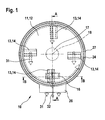
- a device 10 which comprises a release agent 11.
- the Release agent 11 is in this embodiment as a disc-shaped cutting plate 12th educated.
- the cutting plate 12 has several, preferably eight evenly over The circumference distributed dividers 13, which is usually used as a knife 14th are formed.
- four blades 14 are distributed over the circumference.
- other release means 13 may be used, e.g. Split, shear or Impact elements or the like.
- the four blades 14 and their cutting edges are formed radially aligned and adjustable. Through the adjustment or adjustment the knife 14, the wear of the blade 14 and the cutting edges, the is caused in particular by the regrinding of the cutting edges balanced become.
- the position of the entire cutting plate 12th be changeable, in which case the knife 14 (stationary) firmly attached to the cutting plate 12 are.
- the blades 14 form a cutting plane 15, which is parallel to the cutting plate 12th spans or extends.
- the blades 14 have an angle of attack ⁇ of about 10 ° 50 °, with the preferred inclination of the blades 14 with respect to the cutting plane 15 is about 13 ° to 24 °.
- the device 10 has a (not shown) on, by means of a tobacco cake 16 to the release agent 11 and the cutting plate 12 can be moved, in the region of the cutting plane 15th
- This feeder can be used as a conveyor belt, conveyor chain or other common Be formed supply means.
- the cutting plate 12 is arranged on a shaft 17, which is rotatably driven about a rotation axis 18.
- the cutting plate 12 itself points in Area of the blade 14 each have a breakthrough 19.
- the openings 19 are as Through opening formed so that a passage from the front 20 of the Cutting plate 12 on which the tobacco cake 16 is supplied to the back 21 of the Cutting plate 12 on which the separated tobacco is discharged, is created.
- the cutting plate 12 borders with its geometry on the Front 20 located cutting zone 22 of a located on the back 21 Schonzone 23 from.
- the zone of protection 23 is surrounded by a housing 24 which the Protective zone 23 almost completely closes from the environment.
- each breakthrough 19 expediently a funnel-shaped, towards the back 21 opening shape (see in particular Figures 3 and 4).
- the housing 24 is releasably secured to a base plate 27.
- the base plate 27 is preferably as well as the cutting plate 12 disc-shaped and parallel and spaced from the cutting plate 12 so that the cutting zone 22 between the cutting plate 12 and the base plate 27 is formed.
- the Base plate In the area of feeding the Tobacco cake 16 in the cutting zone 22 and in the cutting plane 15 has the Base plate has an opening 28 through which the tobacco cake 16 in the direction of Cutting plate 12 is conveyed.
- the opening 28 is provided with a mouthpiece 29, to support the targeted and defined feeding the tobacco cake 16.
- the base plate 27 has at least one further opening 30.
- This Opening 30, of which several can be distributed over the circumference, is used for Introducing and / or sucking an air stream 31 formed from ambient air into the Cutting zone 22 and the guard zone 23.
- air is from the cutting zone 22 for the formation of the air flow 31 by the rotational movement of the cutting plate 12 itself sucked.
- the opening 30 is used for "breathing", so filling the cutting zone 22 with air to prevent a vacuum in the cutting zone 22.
- By the air flow 31 is the gentle transport of tobacco tobacco stream 32 consisting of separated tobacco supported by the cutting zone 22 in the sanctuary zone 23.
- To create an active one Air flow 31 can in the region of the base plate 27 also means (not shown) be arranged.
- one is in Cutting direction (see arrow 33) leading, in the transport direction (see arrow 37) of the tobacco cake 16 extending edge 34 of the opening 19 in Cutting direction formed in front of the blade tip 35 of the blade 14.
- the edge 34 has in the region of the front side 20 of the cutting plate 12, a slope 38 which the "Threading" the separated tobacco into the opening 19 facilitates.
- One of the Knife tip 35 trailing edge 36 of the opening 19 extends, starting from the knife tip 35 first at an acute angle ⁇ , preferably of about 10 °, to the knife 14, then to leak in a radius to the sanctuary 23 out. This Geometry ensures a gentle and almost deflection-free transport of the Tobacco from the cutting zone 22 in the sanctuary 23rd
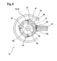
- FIGS. 5 and 6 show a further embodiment of the device 10.
- the same reference numbers are used for identical parts.
- the devices 10 of Figures 1 to 4 on the one hand and Figures 5 and 6 on the other hand in principle are built on the same principle and work will be on a detailed Description of the same features and designs omitted.
- the Device 10 according to Figures 5 and 6 as a release agent 11 a drum 41.
- the Hollow drum 41 also has four, in preferred Embodiments also eight, evenly distributed over the circumference separating elements 13th or knife 14, which corresponds to the cutting plane 15 cutting circuit 15th describe.
- the drum 41 itself is rotationally driven about a rotation axis 42.
- the Knives 14 extend parallel in the direction of the axis of rotation 42.
- the mouthpiece 29 is arranged so that the Cutting zone 22 between tobacco cake 16 and drum 41 is formed.
- the sanctuary 23 is formed inside the drum 41.
- the front side 20 is the side on which the tobacco cake 16 is supplied.
- the interior of the drum 41 corresponds to the back 21.
- Die Cutting plane 15 has in the second embodiment, a slight curvature parallel to Peripheral surface of the drum 41 extends.
- the angle of attack ⁇ of the blade 14 to Cutting plane 15 substantially corresponds to that of the first embodiment.
- the air flow 43 is transverse to the drum 41, namely in the direction of the axis of rotation 42.
- the air flow 43 is by suitable means producible, preferably with a (not shown) blower.
- the air flow 31 can on the one hand by rotation of the drum 41 itself in conjunction with the transverse to Drum 41 directed air flow 43 may be formed, so that a suction effect from the outside is generated inside the drum 41.
- the airflow 31 can also be optional produced by additional means.
- the reference numeral 44 is the cutting direction the drum 41 denotes.
- the tobacco cake 16 is continuously guided to the cutting plate 12 and the drum 41, so that the tobacco cake 16 abuts against the cutting plate 12 and the drum 41.
- the blades 14 reach the position at which the tobacco is separated from the tobacco cake 16.
- the severing can be a cutting, splitting, shearing or the like and inter alia depends essentially on the density of the material to be separated. that does not have to be exclusively tobacco.
- the separation process starts on the upper side of the tobacco cake 16.
- the separated tobacco is - the tobacco stream 32 forming - immediately and immediately passed from the cutting zone 22 in the sanctuary zone 23.
- the transport from the cutting zone 22 into the guard zone 23 is optionally assisted by the air flow 31 which is sucked in by the rotation of the separating means 11 itself, so that the air flow 31 at the cutting plate 12 from the front 20 to the back 21 and the drum 41st From the outside to the inside is passed through the apertures 19.
- the tobacco stream 32 is initially almost linear, ie transported without the tobacco stream 32 accelerating or destroying deflections in the sanctuary zone 23. Since the guard zone 23 is free of any components of the device 10 itself, the collision of the tobacco stream 32 with other components can be prevented.
- the tobacco stream 32 is therefore decelerated in the sanctuary 23 only by its own air resistance.
- the braking effect is also supported by the different flow velocities, due to the small cross section in the area of the knives 14 or the cutting zone 22 on the one hand and the expanded cross section in the area of the guard zone 23 on the other hand.
- the tobacco stream 32 is then in the device 10 according to Figures 1 to 4 by its gravity and optionally supported by the Air flow 31 gently directed in the direction of the discharge chute 26, where the Tobacco stream 32 then hits the discharge system at low speed.
- the Tobacco flow 32 in the device 10 according to Figures 5 and 6 is characterized by the additional air flow 43 from the sanctuary zone 23 to an exit opening from the Drum 41 out.
Landscapes
- Manufacturing Of Cigar And Cigarette Tobacco (AREA)
- Manufacture Of Tobacco Products (AREA)
Abstract
Description
- Fig. 1
- eine Vorderansicht einer ersten Ausführungsform der Vorrichtung zum Trennen von Tabak von einem Tabakkuchen,
- Fig. 2
- eine Ansicht gemäß Schnitt A-A der Vorrichtung gemäß Figur 1,
- Fig. 3
- eine Ansicht gemäß Schnitt B-B der Vorrichtung gemäß Figur 1,
- Fig. 4
- eine Detaildarstellung F des Messers gemäß Figur 3in starker Vergrößerung,
- Fig. 5
- eine perspektivische Ansicht einer weiteren Ausführungsform der Vorrichtung zum Trennen von Tabak von einem Tabakkuchen, und
- Fig. 6
- eine Seitenansicht der Vorrichtung gemäß Figur 5 im Vollschnitt.
Der Tabakkuchen 16 wird kontinuierlich an den Schneidteller 12 bzw. die Trommel 41 geführt, so daß der Tabakkuchen 16 an der Schneidplatte 12 bzw. der Trommel 41 anliegt. Durch Rotieren der Schneidplatte 12 bzw. der Trommel 41 gelangen die Messer 14 in die Position, an der der Tabak vom Tabakkuchen 16 getrennt wird. Bei der Vorrichtung 10 gemäß Figuren 1 bis 4 treffen die Messer 14 seitlich auf den Tabakkuchen 16 und trennen den Tabak vom Tabakkuchen 16. Das Trennen kann ein Schneiden, Spalten, Scheren oder dergleichen sein und hängt u.a. wesentlich von der Dichte des zu trennenden Materials, das nicht ausschließlich Tabak sein muß, ab. Bei der Vorrichtung 10 gemäß Figuren 5 und 6 setzt der Trennvorgang auf der Oberseite des Tabakkuchens 16 an. Der abgetrennte Tabak wird - den Tabakstrom 32 bildend - sofort und unmittelbar von der Schneidzone 22 in die Schonzone 23 geleitet. Der Transport von der Schneidzone 22 in die Schonzone 23 wird optional durch den Luftstrom 31 unterstützt, der durch die Rotation des Trennmittels 11 selbst angesaugt wird, so daß der Luftstrom 31 beim Schneidteller 12 von der Vorderseite 20 auf die Rückseite 21 und bei der Trommel 41 von außen nach innen geleitet wird, und zwar durch die Durchbrüche 19. Durch die weiter oben beschriebene Geometrie und Anordnung der Durchbrüche 19 wird der Tabakstrom 32 zunächst nahezu linear, d.h. ohne den Tabakstrom 32 beschleunigende oder zerstörende Umlenkungen in die Schonzone 23 transportiert. Da die Schonzone 23 frei von irgendwelchen Komponenten der Vorrichtung 10 selbst ist, kann auch die Kollision des Tabakstroms 32 mit anderen Komponenten verhindert werden. Der Tabakstrom 32 wird in der Schonzone 23 daher lediglich durch seinen eigenen Luftwiderstand abgebremst. Der Bremseffekt wird auch durch die unterschiedlichen Strömungsgeschwindigkeiten, bedingt durch den kleinen Querschnitt im Bereich der Messer 14 bzw. der Schneidzone 22 einerseits und den aufgeweiteten Querschnitt im Bereich der Schonzone 23 andererseits, unterstützt.
Claims (23)
- Vorrichtung zum Trennen von Tabak von einem Tabakkuchen (16) umfassend ein rotierend antreibbares Trennmittel (11) mit mindestens einem Trennelement (13) sowie eine Zuführung zum Zuführen des Tabakkuchens (16) in die durch das oder jedes Trennelement (13) gebildete Schneidebene (15), dadurch gekennzeichnet, daß das Trennmittel (11) im Bereich jedes Trennelementes (13) einen Durchbruch (19) aufweist, der derart ausgebildet ist, daß der vom Tabakkuchen (16) abgetrennte Tabak zwangsläufig aus der Schneidebene (15) auf die dem Tabakkuchen (16) abgewandte Seite des Trennmittels (11) geleitet wird.
- Vorrichtung nach Anspruch 1, dadurch gekennzeichnet, daß das Trennmittel (11) mehrere Trennelemente (13), die als Messer (14) ausgebildet sind, aufweist.
- Vorrichtung nach Anspruch 2, dadurch gekennzeichnet, daß das Trennmittel (11) acht verstellbare Messer (14) aufweist, die gleichmäßig über den Umfang des Trennmittels (11) verteilt angeordnet sind.
- Vorrichtung nach Anspruch 2 oder 3, dadurch gekennzeichnet, daß die Messer (14) einen Anstellwinkel α von ca. 10° bis 50°, vorzugsweise etwa 13° bis 24°, zur Schneidebene (15) aufweisen.
- Vorrichtung nach Anspruch 1 oder 2, dadurch gekennzeichnet, daß auf der dem Tabakkuchen (16) zugewandten Vorderseite (20) des Trennmittels (11) eine Schneidzone (22) und auf der dem Tabakkuchen (16) abgewandten Rückseite (21) des Trennmittels (11) eine Schonzone (23) vorgesehen ist.
- Vorrichtung nach einem der Ansprüche 1 bis 3, dadurch gekennzeichnet, daß der vom Tabakkuchen (16) abgetrennte Tabak frei von Umlenkungen, also nahezu linear von der Vorderseite (20) auf die Rückseite (21) des Trennmittels (11) förderbar ist.
- Vorrichtung nach einem der Ansprüche 1 bis 6, dadurch gekennzeichnet, daß jeder Durchbruch (19) eine trichterförmige, zur von dem Tabakkuchen (16) abgewandten Seite des Trennmittels (11) hin sich öffnende Gestalt aufweist.
- Vorrichtung nach einem der Ansprüche 1 bis 7, dadurch gekennzeichnet, daß das Trennmittel (11) als Schneidteller (12) ausgebildet ist, wobei der Schneidteller (12) auf einer die Drehachse (18) bestimmenden Welle (17) angeordnet ist.
- Vorrichtung nach Anspruch 8, dadurch gekennzeichnet, daß die Messer (14) derart auf dem Schneidteller (12) angeordnet sind, daß deren Schneidkanten radial ausgerichtet sind.
- Vorrichtung nach Anspruch 8 oder 9, dadurch gekennzeichnet, daß dem Schneidteller (12) auf der Vorderseite (20) eine Grundplatte (27) zugeordnet ist, wobei der Schneidteller (12) und die Grundplatte (27) zur Bildung der Schneidzone (22) beabstandet zueinander angeordnet sind.
- Vorrichtung nach Anspruch 10, dadurch gekennzeichnet, daß die Grundplatte (27) ein Mundstück (29) zur definierten Zuführung des Tabakkuchens (16) in den Bereich der Schneidebene (15) aufweist.
- Vorrichtung nach Anspruch 10 oder 11, dadurch gekennzeichnet, daß die Grundplatte (27) mindestens eine weitere Öffnung (30) zum Einleiten und/oder Ansaugen eines Luftstroms (31) aufweist.
- Vorrichtung nach einem der Ansprüche 10 bis 12, dadurch gekennzeichnet, daß an der Grundplatte (27) ein Gehäuse (24) zur Bildung der Schonzone (23) auf der Rückseite (21) der Schneidplatte (12) angeordnet ist.
- Vorrichtung nach Anspruch 13, dadurch gekennzeichnet, daß das Gehäuse (24) einen Auswurfschacht (26) zum Weiterleiten des abgetrennten Tabaks an ein nachgeordnetes Abfuhrsystem aufweist.
- Vorrichtung nach einem der Ansprüche 1 bis 7, dadurch gekennzeichnet, daß das Trennmittel (11) als Hohltrommel (41) ausgebildet ist, wobei die Hohltrommel (41) um die Drehachse (42) drehbar ist.
- Vorrichtung nach Anspruch 15, dadurch gekennzeichnet, daß die Messer (14) im Bereich der Umfangsfläche der Trommel (41) angeordnet sind und sich parallel zur Drehachse (42) erstrecken.
- Vorrichtung nach Anspruch 15 oder 16, dadurch gekennzeichnet, daß ein Mundstück (29) zur definierten Zuführung des Tabakkuchens (16) in den Bereich des Schneidkreises (15) vorgesehen ist.
- Vorrichtung nach einem der Ansprüche 15 bis 17, dadurch gekennzeichnet, daß Mittel zum Einleiten eines Luftstromes (43) in die der Schonzone (23) parallel zur Drehachse (42) und/oder eines radialen Luftstromes (31) quer zur Drehachse (42) vorgesehen sind.
- Vorrichtung nach einem der Ansprüche 15 bis 18, dadurch gekennzeichnet, daß die Hohltrommel (41) an einer Stirnseite eine Auswurföffnung zum Weiterleiten des abgetrennten Tabaks an ein nachgeordnetes Abfuhrsystem aufweist.
- Verfahren zum Trennen von Tabak von einem Tabakkuchen, umfassend die Schrittedadurch gekennzeichnet,daßTransportieren des Tabakkuchens (16) in den Bereich der Schneidebene (15) eines mit mindestens einem Trennelement (13) versehenen, rotierenden Trennmittels (11),Trennen des Tabaks vom Tabakkuchen (16) mit dem Trennelement (13),Ableiten des vom Tabakkuchen (16) abgetrennten Tabaks an ein nachgeordnetes Abfuhrsystem,der abgetrennte Tabak unmittelbar nach dem Abtrennen vom Tabakkuchen (16) zwangsläufig aus der Schneidebene (15) durch das Trennmittel (11) hindurch auf die dem Tabakkuchen (16) abgewandte Seite des Trennmittels (11) geleitet wird.
- Verfahren nach Anspruch 20, dadurch gekennzeichnet, daß das Fördern des abgetrennten Tabaks vom Tabakkuchen (16) von der Schneidebene (15) auf die dem Tabakkuchen (16) abgewandte Seite in linearer Ausrichtung erfolgt.
- Verfahren nach Anspruch 20 oder 21, dadurch gekennzeichnet, daß der Transport von einer Schneidzone (22) vor dem Trennmittel (11) in eine Schonzone (23) hinter dem Trennmittel (11) umlenkungsfrei erfolgt.
- Verfahren nach Anspruch 22, dadurch gekennzeichnet, daß der abgetrennte Tabak in der Schonzone (23) lediglich durch seinen eigenen Luftwiderstand abgebremst wird.
Priority Applications (2)
| Application Number | Priority Date | Filing Date | Title |
|---|---|---|---|
| PL04090198T PL1477074T3 (pl) | 2003-05-16 | 2004-05-17 | Sposób odcinania tytoniu z placka tytoniowego oraz urządzenie do przeprowadzania tego sposobu |
| EP04090198A EP1477074B1 (de) | 2003-05-16 | 2004-05-17 | Verfahren zum Trennen von Tabak von einem Tabakkuchen sowie Vorrichtung zur Durchführung des Verfahrens |
Applications Claiming Priority (3)
| Application Number | Priority Date | Filing Date | Title |
|---|---|---|---|
| EP03090145 | 2003-05-16 | ||
| EP03090145 | 2003-05-16 | ||
| EP04090198A EP1477074B1 (de) | 2003-05-16 | 2004-05-17 | Verfahren zum Trennen von Tabak von einem Tabakkuchen sowie Vorrichtung zur Durchführung des Verfahrens |
Publications (3)
| Publication Number | Publication Date |
|---|---|
| EP1477074A1 true EP1477074A1 (de) | 2004-11-17 |
| EP1477074A8 EP1477074A8 (de) | 2005-02-09 |
| EP1477074B1 EP1477074B1 (de) | 2007-08-08 |
Family
ID=33522358
Family Applications (1)
| Application Number | Title | Priority Date | Filing Date |
|---|---|---|---|
| EP04090198A Expired - Lifetime EP1477074B1 (de) | 2003-05-16 | 2004-05-17 | Verfahren zum Trennen von Tabak von einem Tabakkuchen sowie Vorrichtung zur Durchführung des Verfahrens |
Country Status (7)
| Country | Link |
|---|---|
| EP (1) | EP1477074B1 (de) |
| JP (1) | JP4597572B2 (de) |
| CN (1) | CN100409774C (de) |
| AT (1) | ATE369046T1 (de) |
| DE (1) | DE502004004550D1 (de) |
| ES (1) | ES2289431T3 (de) |
| PL (1) | PL1477074T3 (de) |
Cited By (1)
| Publication number | Priority date | Publication date | Assignee | Title |
|---|---|---|---|---|
| WO2012057642A1 (en) * | 2010-10-29 | 2012-05-03 | International Tobacco Machinery Poland Sp. Z O.O. | Blade assembly for a tobacco cutter |
Families Citing this family (2)
| Publication number | Priority date | Publication date | Assignee | Title |
|---|---|---|---|---|
| CN102715634B (zh) * | 2012-07-05 | 2014-03-05 | 巩义市长征新科真空机械厂 | 压缩空气烟把切割解把系统 |
| CN110154118B (zh) * | 2019-06-25 | 2024-02-23 | 重庆长征重工有限责任公司 | 一种能够自动补偿的旋转刀装置 |
Citations (5)
| Publication number | Priority date | Publication date | Assignee | Title |
|---|---|---|---|---|
| GB665653A (en) * | 1949-04-05 | 1952-01-30 | Robert Legg Ltd | Improvements in or relating to machines for cutting tobacco and similar materials |
| DE883575C (de) * | 1951-07-06 | 1954-08-09 | Kurt Koerber & Co K G | Antriebsvorrichtung fuer den Schleifmechanismus an Walzentabakschneidern |
| US3604489A (en) * | 1969-12-23 | 1971-09-14 | Philip Morris Inc | Grinding mill |
| EP0584524A1 (de) * | 1992-08-03 | 1994-03-02 | COMAS S.p.A. | Rotierendes Schneidwerkzeug, insbesondere zum Schneiden von Tabak |
| EP1234510A1 (de) * | 2001-02-27 | 2002-08-28 | Heat and Control, Inc. | Gleichzeitiges Schneiden und Waschen von Gemüse |
Family Cites Families (2)
| Publication number | Priority date | Publication date | Assignee | Title |
|---|---|---|---|---|
| JPS5828265A (ja) * | 1981-07-23 | 1983-02-19 | エイエムエフ・インコ−ポレ−テツド | 積層材料の切断方法および切断装置 |
| WO1995007031A1 (en) * | 1993-09-07 | 1995-03-16 | Fabriques De Tabac Reunies Sa | Rotary cutter |
-
2004
- 2004-05-14 CN CNB2004100432162A patent/CN100409774C/zh not_active Expired - Fee Related
- 2004-05-14 JP JP2004144747A patent/JP4597572B2/ja not_active Expired - Fee Related
- 2004-05-17 EP EP04090198A patent/EP1477074B1/de not_active Expired - Lifetime
- 2004-05-17 ES ES04090198T patent/ES2289431T3/es not_active Expired - Lifetime
- 2004-05-17 AT AT04090198T patent/ATE369046T1/de not_active IP Right Cessation
- 2004-05-17 PL PL04090198T patent/PL1477074T3/pl unknown
- 2004-05-17 DE DE502004004550T patent/DE502004004550D1/de not_active Expired - Lifetime
Patent Citations (5)
| Publication number | Priority date | Publication date | Assignee | Title |
|---|---|---|---|---|
| GB665653A (en) * | 1949-04-05 | 1952-01-30 | Robert Legg Ltd | Improvements in or relating to machines for cutting tobacco and similar materials |
| DE883575C (de) * | 1951-07-06 | 1954-08-09 | Kurt Koerber & Co K G | Antriebsvorrichtung fuer den Schleifmechanismus an Walzentabakschneidern |
| US3604489A (en) * | 1969-12-23 | 1971-09-14 | Philip Morris Inc | Grinding mill |
| EP0584524A1 (de) * | 1992-08-03 | 1994-03-02 | COMAS S.p.A. | Rotierendes Schneidwerkzeug, insbesondere zum Schneiden von Tabak |
| EP1234510A1 (de) * | 2001-02-27 | 2002-08-28 | Heat and Control, Inc. | Gleichzeitiges Schneiden und Waschen von Gemüse |
Cited By (1)
| Publication number | Priority date | Publication date | Assignee | Title |
|---|---|---|---|---|
| WO2012057642A1 (en) * | 2010-10-29 | 2012-05-03 | International Tobacco Machinery Poland Sp. Z O.O. | Blade assembly for a tobacco cutter |
Also Published As
| Publication number | Publication date |
|---|---|
| DE502004004550D1 (de) | 2007-09-20 |
| ATE369046T1 (de) | 2007-08-15 |
| JP4597572B2 (ja) | 2010-12-15 |
| PL1477074T3 (pl) | 2007-12-31 |
| EP1477074A8 (de) | 2005-02-09 |
| CN100409774C (zh) | 2008-08-13 |
| EP1477074B1 (de) | 2007-08-08 |
| JP2004337168A (ja) | 2004-12-02 |
| CN1550162A (zh) | 2004-12-01 |
| ES2289431T3 (es) | 2008-02-01 |
Similar Documents
| Publication | Publication Date | Title |
|---|---|---|
| EP1031273B1 (de) | Mähdrescher mit Breitverteileraustrag für gehäckseltes Stroh-Spreu-Gemisch | |
| EP0184786B1 (de) | Vorrichtung zum Vernichten von Banknoten | |
| EP0331784B1 (de) | Spleisshäcksler | |
| DE3789232T2 (de) | Mähdrescher mit angebautem, drehbarem strohhäcksler. | |
| EP3291915B1 (de) | Zerkleinerungsmaschine mit einem rotorsystem und verfahren zum zerkleinern von aufgabegut | |
| DE102015104155B4 (de) | Trennvorrichtung zum Trennen eines Stranges aus pastöser Lebensmittel-Masse | |
| EP2289356A1 (de) | Vorrichtung zur Verarbeitung von Rauchartikelabfällen | |
| DE102007059625B4 (de) | Strangschneidvorrichtung | |
| EP3520596A1 (de) | Mähdrescher | |
| EP2825354B1 (de) | Schneidmesser mit einem mittel zur erzeugung eines luftstroms | |
| DE102016212096B4 (de) | Vorrichtung und Verfahren zum Eröffnen von Ausschusszigaretten und Einrichtung zur Separation von Ausschussmaterialien der Zigarettenherstellung | |
| EP0744257B1 (de) | Zerspaner für Hackschnitzel | |
| EP0124138A2 (de) | Verfahren und Vorrichtung zur Zerkleinerung von Pflanzengut | |
| EP1477074B1 (de) | Verfahren zum Trennen von Tabak von einem Tabakkuchen sowie Vorrichtung zur Durchführung des Verfahrens | |
| DE2640334C2 (de) | Feldhäcksler | |
| EP1027820A1 (de) | Spreuverteiler für einen Mähdrescher | |
| DE3306068A1 (de) | Zerkleinerungsvorrichtung und verfahren insbesondere zur herstellung von holzspaenen | |
| DE2938215A1 (de) | Zerkleinerungsvorrichtung, insbesondere fuer holz | |
| EP3598904B1 (de) | Maschine der tabak verarbeitenden industrie zum beschicken einer strangmaschine sowie verfahren zum betreiben einer solchen maschine | |
| EP1643825A1 (de) | Verfahren zum trennen der äusseren faserschichten von den kerne bildenden samen von hanfpflanzen | |
| DE102004050926A1 (de) | Zerkleinerungsmaschine | |
| DE4001122A1 (de) | Verfahren zum krabbenschaelen sowie vorrichtung zur durchfuehrung des verfahrens | |
| DE102012009028A1 (de) | Einrichtung zur Beeinflussung der Bewegung einer Produktscheibe | |
| DE8907251U1 (de) | Vorrichtung zum Zerkleinern und Entsorgen von organ. Haus- und Gartenabfällen | |
| DE647942C (de) | Mahlvorrichtung |
Legal Events
| Date | Code | Title | Description |
|---|---|---|---|
| PUAI | Public reference made under article 153(3) epc to a published international application that has entered the european phase |
Free format text: ORIGINAL CODE: 0009012 |
|
| AK | Designated contracting states |
Kind code of ref document: A1 Designated state(s): AT BE BG CH CY CZ DE DK EE ES FI FR GB GR HU IE IT LI LU MC NL PL PT RO SE SI SK TR |
|
| AX | Request for extension of the european patent |
Extension state: AL HR LT LV MK |
|
| RIN1 | Information on inventor provided before grant (corrected) |
Inventor name: SCHWARZ, EUGEN Inventor name: HAMKENS, HAUKE-PETER Inventor name: BRANDT, HOLGER Inventor name: BUHK, BIRGER |
|
| 17P | Request for examination filed |
Effective date: 20050511 |
|
| GRAP | Despatch of communication of intention to grant a patent |
Free format text: ORIGINAL CODE: EPIDOSNIGR1 |
|
| AKX | Designation fees paid |
Designated state(s): AT BE BG CH CY CZ DE DK EE ES FI FR GB GR HU IE IT LI LU MC NL PL PT RO SE SI SK TR |
|
| GRAS | Grant fee paid |
Free format text: ORIGINAL CODE: EPIDOSNIGR3 |
|
| GRAA | (expected) grant |
Free format text: ORIGINAL CODE: 0009210 |
|
| AK | Designated contracting states |
Kind code of ref document: B1 Designated state(s): AT BE BG CH CY CZ DE DK EE ES FI FR GB GR HU IE IT LI LU MC NL PL PT RO SE SI SK TR |
|
| REG | Reference to a national code |
Ref country code: GB Ref legal event code: FG4D Free format text: NOT ENGLISH |
|
| REG | Reference to a national code |
Ref country code: CH Ref legal event code: EP |
|
| REG | Reference to a national code |
Ref country code: IE Ref legal event code: FG4D Free format text: LANGUAGE OF EP DOCUMENT: GERMAN |
|
| REF | Corresponds to: |
Ref document number: 502004004550 Country of ref document: DE Date of ref document: 20070920 Kind code of ref document: P |
|
| GBT | Gb: translation of ep patent filed (gb section 77(6)(a)/1977) |
Effective date: 20071003 |
|
| REG | Reference to a national code |
Ref country code: PL Ref legal event code: T3 |
|
| PG25 | Lapsed in a contracting state [announced via postgrant information from national office to epo] |
Ref country code: BG Free format text: LAPSE BECAUSE OF FAILURE TO SUBMIT A TRANSLATION OF THE DESCRIPTION OR TO PAY THE FEE WITHIN THE PRESCRIBED TIME-LIMIT Effective date: 20071108 Ref country code: FI Free format text: LAPSE BECAUSE OF FAILURE TO SUBMIT A TRANSLATION OF THE DESCRIPTION OR TO PAY THE FEE WITHIN THE PRESCRIBED TIME-LIMIT Effective date: 20070808 |
|
| REG | Reference to a national code |
Ref country code: ES Ref legal event code: FG2A Ref document number: 2289431 Country of ref document: ES Kind code of ref document: T3 |
|
| ET | Fr: translation filed | ||
| REG | Reference to a national code |
Ref country code: IE Ref legal event code: FD4D |
|
| PG25 | Lapsed in a contracting state [announced via postgrant information from national office to epo] |
Ref country code: GR Free format text: LAPSE BECAUSE OF FAILURE TO SUBMIT A TRANSLATION OF THE DESCRIPTION OR TO PAY THE FEE WITHIN THE PRESCRIBED TIME-LIMIT Effective date: 20071109 Ref country code: DK Free format text: LAPSE BECAUSE OF FAILURE TO SUBMIT A TRANSLATION OF THE DESCRIPTION OR TO PAY THE FEE WITHIN THE PRESCRIBED TIME-LIMIT Effective date: 20070808 |
|
| PG25 | Lapsed in a contracting state [announced via postgrant information from national office to epo] |
Ref country code: PT Free format text: LAPSE BECAUSE OF FAILURE TO SUBMIT A TRANSLATION OF THE DESCRIPTION OR TO PAY THE FEE WITHIN THE PRESCRIBED TIME-LIMIT Effective date: 20080108 Ref country code: SK Free format text: LAPSE BECAUSE OF FAILURE TO SUBMIT A TRANSLATION OF THE DESCRIPTION OR TO PAY THE FEE WITHIN THE PRESCRIBED TIME-LIMIT Effective date: 20070808 Ref country code: CZ Free format text: LAPSE BECAUSE OF FAILURE TO SUBMIT A TRANSLATION OF THE DESCRIPTION OR TO PAY THE FEE WITHIN THE PRESCRIBED TIME-LIMIT Effective date: 20070808 Ref country code: IE Free format text: LAPSE BECAUSE OF FAILURE TO SUBMIT A TRANSLATION OF THE DESCRIPTION OR TO PAY THE FEE WITHIN THE PRESCRIBED TIME-LIMIT Effective date: 20070808 |
|
| PLBE | No opposition filed within time limit |
Free format text: ORIGINAL CODE: 0009261 |
|
| STAA | Information on the status of an ep patent application or granted ep patent |
Free format text: STATUS: NO OPPOSITION FILED WITHIN TIME LIMIT |
|
| PG25 | Lapsed in a contracting state [announced via postgrant information from national office to epo] |
Ref country code: SE Free format text: LAPSE BECAUSE OF FAILURE TO SUBMIT A TRANSLATION OF THE DESCRIPTION OR TO PAY THE FEE WITHIN THE PRESCRIBED TIME-LIMIT Effective date: 20071108 Ref country code: RO Free format text: LAPSE BECAUSE OF FAILURE TO SUBMIT A TRANSLATION OF THE DESCRIPTION OR TO PAY THE FEE WITHIN THE PRESCRIBED TIME-LIMIT Effective date: 20070808 |
|
| 26N | No opposition filed |
Effective date: 20080509 |
|
| BERE | Be: lapsed |
Owner name: HAUNI MASCHINENBAU A.G. Effective date: 20080531 |
|
| PG25 | Lapsed in a contracting state [announced via postgrant information from national office to epo] |
Ref country code: MC Free format text: LAPSE BECAUSE OF NON-PAYMENT OF DUE FEES Effective date: 20080531 |
|
| PG25 | Lapsed in a contracting state [announced via postgrant information from national office to epo] |
Ref country code: EE Free format text: LAPSE BECAUSE OF FAILURE TO SUBMIT A TRANSLATION OF THE DESCRIPTION OR TO PAY THE FEE WITHIN THE PRESCRIBED TIME-LIMIT Effective date: 20070808 |
|
| REG | Reference to a national code |
Ref country code: FR Ref legal event code: ST Effective date: 20090119 |
|
| PG25 | Lapsed in a contracting state [announced via postgrant information from national office to epo] |
Ref country code: BE Free format text: LAPSE BECAUSE OF NON-PAYMENT OF DUE FEES Effective date: 20080531 |
|
| PG25 | Lapsed in a contracting state [announced via postgrant information from national office to epo] |
Ref country code: FR Free format text: LAPSE BECAUSE OF NON-PAYMENT OF DUE FEES Effective date: 20080602 |
|
| PG25 | Lapsed in a contracting state [announced via postgrant information from national office to epo] |
Ref country code: SI Free format text: LAPSE BECAUSE OF FAILURE TO SUBMIT A TRANSLATION OF THE DESCRIPTION OR TO PAY THE FEE WITHIN THE PRESCRIBED TIME-LIMIT Effective date: 20070808 |
|
| REG | Reference to a national code |
Ref country code: ES Ref legal event code: FD2A Effective date: 20080519 |
|
| PG25 | Lapsed in a contracting state [announced via postgrant information from national office to epo] |
Ref country code: CY Free format text: LAPSE BECAUSE OF FAILURE TO SUBMIT A TRANSLATION OF THE DESCRIPTION OR TO PAY THE FEE WITHIN THE PRESCRIBED TIME-LIMIT Effective date: 20070808 |
|
| PG25 | Lapsed in a contracting state [announced via postgrant information from national office to epo] |
Ref country code: AT Free format text: LAPSE BECAUSE OF NON-PAYMENT OF DUE FEES Effective date: 20080517 |
|
| PG25 | Lapsed in a contracting state [announced via postgrant information from national office to epo] |
Ref country code: ES Free format text: LAPSE BECAUSE OF NON-PAYMENT OF DUE FEES Effective date: 20080519 |
|
| PG25 | Lapsed in a contracting state [announced via postgrant information from national office to epo] |
Ref country code: LU Free format text: LAPSE BECAUSE OF NON-PAYMENT OF DUE FEES Effective date: 20080517 Ref country code: HU Free format text: LAPSE BECAUSE OF FAILURE TO SUBMIT A TRANSLATION OF THE DESCRIPTION OR TO PAY THE FEE WITHIN THE PRESCRIBED TIME-LIMIT Effective date: 20080209 |
|
| PG25 | Lapsed in a contracting state [announced via postgrant information from national office to epo] |
Ref country code: TR Free format text: LAPSE BECAUSE OF FAILURE TO SUBMIT A TRANSLATION OF THE DESCRIPTION OR TO PAY THE FEE WITHIN THE PRESCRIBED TIME-LIMIT Effective date: 20070808 |
|
| PGFP | Annual fee paid to national office [announced via postgrant information from national office to epo] |
Ref country code: NL Payment date: 20160509 Year of fee payment: 13 |
|
| REG | Reference to a national code |
Ref country code: DE Ref legal event code: R081 Ref document number: 502004004550 Country of ref document: DE Owner name: HAUNI MASCHINENBAU GMBH, DE Free format text: FORMER OWNER: HAUNI MASCHINENBAU AG, 21033 HAMBURG, DE |
|
| PGFP | Annual fee paid to national office [announced via postgrant information from national office to epo] |
Ref country code: GB Payment date: 20160512 Year of fee payment: 13 Ref country code: CH Payment date: 20160512 Year of fee payment: 13 |
|
| REG | Reference to a national code |
Ref country code: CH Ref legal event code: PFA Owner name: HAUNI MASCHINENBAU GMBH, DE Free format text: FORMER OWNER: HAUNI MASCHINENBAU AG, DE |
|
| REG | Reference to a national code |
Ref country code: NL Ref legal event code: PD Owner name: HAUNI MASCHINENBAU GMBH; DE Free format text: DETAILS ASSIGNMENT: VERANDERING VAN EIGENAAR(S), VERANDERING VAN DE JURIDISCHE ENTITEIT; FORMER OWNER NAME: HAUNI MASCHINENBAU AG Effective date: 20160928 |
|
| REG | Reference to a national code |
Ref country code: CH Ref legal event code: PL |
|
| REG | Reference to a national code |
Ref country code: NL Ref legal event code: MM Effective date: 20170601 |
|
| GBPC | Gb: european patent ceased through non-payment of renewal fee |
Effective date: 20170517 |
|
| PG25 | Lapsed in a contracting state [announced via postgrant information from national office to epo] |
Ref country code: LI Free format text: LAPSE BECAUSE OF NON-PAYMENT OF DUE FEES Effective date: 20170531 Ref country code: CH Free format text: LAPSE BECAUSE OF NON-PAYMENT OF DUE FEES Effective date: 20170531 |
|
| PG25 | Lapsed in a contracting state [announced via postgrant information from national office to epo] |
Ref country code: NL Free format text: LAPSE BECAUSE OF NON-PAYMENT OF DUE FEES Effective date: 20170601 |
|
| PG25 | Lapsed in a contracting state [announced via postgrant information from national office to epo] |
Ref country code: GB Free format text: LAPSE BECAUSE OF NON-PAYMENT OF DUE FEES Effective date: 20170517 |
|
| PGFP | Annual fee paid to national office [announced via postgrant information from national office to epo] |
Ref country code: DE Payment date: 20190529 Year of fee payment: 16 Ref country code: IT Payment date: 20190531 Year of fee payment: 16 Ref country code: PL Payment date: 20190429 Year of fee payment: 16 |
|
| REG | Reference to a national code |
Ref country code: DE Ref legal event code: R119 Ref document number: 502004004550 Country of ref document: DE |
|
| PG25 | Lapsed in a contracting state [announced via postgrant information from national office to epo] |
Ref country code: DE Free format text: LAPSE BECAUSE OF NON-PAYMENT OF DUE FEES Effective date: 20201201 |
|
| PG25 | Lapsed in a contracting state [announced via postgrant information from national office to epo] |
Ref country code: IT Free format text: LAPSE BECAUSE OF NON-PAYMENT OF DUE FEES Effective date: 20200517 |
|
| PG25 | Lapsed in a contracting state [announced via postgrant information from national office to epo] |
Ref country code: PL Free format text: LAPSE BECAUSE OF NON-PAYMENT OF DUE FEES Effective date: 20200517 |