EP1475603B1 - Procédé de calibration pour un instrument pour mesurer la texture d'une surface et ledit instrument - Google Patents
Procédé de calibration pour un instrument pour mesurer la texture d'une surface et ledit instrument Download PDFInfo
- Publication number
- EP1475603B1 EP1475603B1 EP04010601.5A EP04010601A EP1475603B1 EP 1475603 B1 EP1475603 B1 EP 1475603B1 EP 04010601 A EP04010601 A EP 04010601A EP 1475603 B1 EP1475603 B1 EP 1475603B1
- Authority
- EP
- European Patent Office
- Prior art keywords
- arm
- detector
- calibration
- point
- tip
- Prior art date
- Legal status (The legal status is an assumption and is not a legal conclusion. Google has not performed a legal analysis and makes no representation as to the accuracy of the status listed.)
- Expired - Fee Related
Links
Images
Classifications
-
- G—PHYSICS
- G01—MEASURING; TESTING
- G01B—MEASURING LENGTH, THICKNESS OR SIMILAR LINEAR DIMENSIONS; MEASURING ANGLES; MEASURING AREAS; MEASURING IRREGULARITIES OF SURFACES OR CONTOURS
- G01B5/00—Measuring arrangements characterised by the use of mechanical techniques
- G01B5/28—Measuring arrangements characterised by the use of mechanical techniques for measuring roughness or irregularity of surfaces
-
- G—PHYSICS
- G01—MEASURING; TESTING
- G01B—MEASURING LENGTH, THICKNESS OR SIMILAR LINEAR DIMENSIONS; MEASURING ANGLES; MEASURING AREAS; MEASURING IRREGULARITIES OF SURFACES OR CONTOURS
- G01B5/00—Measuring arrangements characterised by the use of mechanical techniques
- G01B5/20—Measuring arrangements characterised by the use of mechanical techniques for measuring contours or curvatures
Definitions
- the present invention relates to a calibration method for a surface texture measuring instrument, a calibration program for a surface texture measuring instrument, a recording medium storing the calibration program and a surface texture measuring instrument.
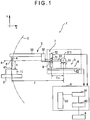
- a surface texture measuring instrument 1 shown in Fig. 1 has an arm 3 with a base end 311 swingably supported, a contact point 41 that is arranged on the other end of the arm 3 for scanning on a workpiece, a first detector 6 for detecting a displacement of the arm 3 in x-direction and a second detector 7 for detecting the swing of the arm 3 as a displacement in z-direction.
- the first detector 6 and the second detector 7 are not designed to directly detect the coordinates of the contact point 41.
- this circular movement causes a deviation undetectable by a displacement detector such as the first detector 6 and the second detector 7. Therefore, in a method applied for obtaining measurement data of the workpiece surface by calculating the coordinate of the contact point 41, the deviation of x-coordinate caused by the circular movement of the arm 3 is defined as dx and that of z-coordinate is defined as dz, and these dx and dz are counted in detection results of the first detector 6 and the second detector 7.
- a gauge with a known height is measured to calibrate the deviation in z-direction. Then, a gauge with a known angle or a spherical gauge is measured to calibrate a symmetry error.
- the z-direction calibration and the subsequent symmetry calibration require considerable time and certain skill since the replacement of reference gauge is necessary in the measurements. Moreover, it is troublesome to set gauges one after another for measuring a plurality of gauges.
- a method proposed in Reference 3 includes a step for measuring a gauge which can be regarded as a substantially perfect circle one time and a step for applying a least-square method that assigns the measurement data in a circle equation, thus enabling a calibration with one measurement and calculation.
- a parameter subjected to the calibration is limited, it is impossible to perform calibration more accurately.
- a method for a calibrating surface texture measuring instrument of the kind that use an arm supported to be swingable around a base point so that a contact point of a stylus tip is in contact with the workpiece along a substantial tangent line of an arc drawn by a tip of the contact point in accordance with a swing of the arm is disclosed in US 2001/029778 A and JP 10 332304 A .
- An object of the present invention is to provide a calibration method for a surface texture measuring instrument for easily and highly accurately calibrating a surface texture measuring instrument, its calibration program, a recording medium storing the calibration program and a surface texture measuring instrument.
- the object is achieved by a method for calibrating a surface texture measuring instrument as claimed in claim 1, a program for the surface texture measuring instrument, as claimed in claim 7, a recording medium storing the program as claimed in claim 8 and a surface texture measuring instrument as claimed in claim 9.
- Preferred embodiments are disclosed in the dependent claims.
- a calibration method for a surface texture measuring instrument that measures a surface of a workpiece, the instrument including: an arm supported to be swingable around a base point; a stylus that is arranged on an end of the arm and is provided with a contact point on a tip thereof, the contact point being in contact or nearly in contact with the workpiece along a substantial tangent line of an arc drawn by a tip of the contact point in accordance with a swing of the arm; a shifter for shifting the arm in x-direction while keeping the contact point in contact or nearly in contact with the workpiece surface; a first detector for detecting a displacement of the base point in the x-direction; a second detector for detecting a displacement in z-direction due to the swing of the arm based on a displacement of a point on the arm in the z-direction; and a compensation computing unit that compensates detection results of the first detector and the second detector for a deviation due to the swing to obtain measurement data of the workpiece surface
- the calibration gauge is measured to obtain measurement data in the measurement step. Since the calibration gauge has a cross section containing a part of a substantially perfect circle and the data for the perfect circle must satisfy the circle equation, the surface texture measuring instrument can be conversely calibrated by calibrating each parameter to satisfy the circle equation. Therefore, in the assignment step, the data obtained in the measurement step is assigned in the evaluation formula based on the circle equation. Then, each parameter is calibrated by, for example, a least square method in the calibration step.
- each parameter is calibrated by, for example, a least square method in the calibration step.
- the least square method may be applied selectively to a plurality of parameters subjected to calibration.
- the gain of z-coordinate of the tip of the contact point to the detection result of the second detector can be found together. While it is necessary in conventional methods to measure a gauge with a known height to calibrate z-direction deviation, and subsequently to replace with a spherical calibration gauge to calibrate symmetry and the like, the measurement step with this configuration only requires to measure a spherical gauge one time. Therefore, as compared to measurements of a plurality of calibration gauges for each parameter subjected to calibration, this method is convenient and requires less time. If it is configured to automatically calibrate all the parameters subjected to calibration with the use of, for example, the least square method based on the data obtained in the measurement step, there is no need for an operator to replace the calibration gauge. Accordingly, after setting the calibration gauge, the operator need not stay by the surface texture measuring instrument, thereby making the operator free from troublesome work.
- the evaluation formula in the assignment step is determined based on: an arm reference length L as a length from the base point to a reference point as a foot of a perpendicular line extended from the tip of the contact point to a base shaft of the arm extending in longitudinal direction; a detection value xi of the first detector; a detection result zi of the second detector; a gain "g” of the z-coordinate of the tip of the contact point to the detection result zi of the second detector; and a tip compensation amount "h” as a length from the reference point to the tip of the contact point, and with a known arm reference length L being given, the center coordinates (x c , z c ), the radius "r", the gain "g” and the tip compensation amount "h” are found in the calibration step.
- the evaluation formula may be, for example, the following formula.
- f i x i + L 1 ⁇ L 2 ⁇ g z i 2 L ⁇ h g z i L ⁇ x C 2 + g z i + h 1 ⁇ L 2 ⁇ g z i 2 L ⁇ z C 2 ⁇ r
- the calibration method for the surface texture measuring instrument according to a comparative example is based on a designed value of the arm reference length L, the center coordinates (x c , z c ), the radius "r”, the gain "g”, and the tip compensation amount "h" are found in the calibration step.
- the evaluation formula may be, for example, the following formula.
- f i x i + L 1 ⁇ L 2 ⁇ g z i 2 L ⁇ h g z i L ⁇ x C 2 + g z i + h 1 ⁇ L 2 ⁇ g z i 2 L ⁇ z C 2 ⁇ r
- the evaluation formula in the assignment step is determined based on: an arm reference length L as a length from the base point to the tip of the contact point; a detection value x i of the first detector; a detection result z i of the second detector; a gain "g" of the z-coordinate of the tip of the contact point to the detection result z i of the second detector; and a zeroset deviation z o as a value derived by multiplying the detection result of the second detector, which is obtained when a line connecting the base point and the tip of the contact point tip is parallel to the x-direction, by the gain "g", and that the center coordinates (x c , z c ) of the circle, the radius of the circle "r”, the gain "g", the arm reference length L and the zeroset deviation z o are found.
- the evaluation formula in the assignment step is determined based on: an arm reference length L as a length from the base point to a reference point as a foot of a perpendicular line extended from the tip of the contact point to a base shaft of the arm extending in longitudinal direction; a detection value x i of the first detector; detection result z i of the second detector; a gain "g" of the z-coordinate of the tip of the contact point to the detection result z i of the second detector; a tip compensation amount "h” as a length from the reference point to the tip of the contact point; and a zeroset deviation z0 as a value derived by multiplying the detection result of the second detector, which is obtained when the base shaft of the arm is parallel to the x-direction, by the gain "g", and that the center coordinates (x c , z c ) of the circle, the radius of the circle "r", the tip compensation amount "h”,
- the evaluation formula may be, for example, the following formula.
- f i x i + L 1 ⁇ L 2 ⁇ g z i ⁇ z O 2 L ⁇ h g z i ⁇ z O L ⁇ x C 2 + g z i + h 1 ⁇ L 2 ⁇ g z i ⁇ z O L ⁇ z C 2 ⁇ r
- the gain "g”, the tip compensation amount "h”, the zeroset deviation z o , the arm reference length L and the like can be calibrated. Since these parameters are calibrated based on the data obtained in the single measurement in the measurement step, this method is convenient and the calibration can be performed in a short time.
- the calibration method for the surface texture measuring instrument according to the present invention preferably further includes a second calibration step, with a true shape of the calibration gauge being given, for computing a tip shape of the contact point based on difference from the radius "r" found in the calibration step.
- the tip shape of the contact point can be found based on the difference from the radius "r" found in the calibration step.
- the shape of the calibration gauge and the tip shape of the contact point are typically spherical, they are not exactly perfect sphere.
- lengths from the nominal center (x c , z c ) of the sphere to the sphere surface in each angle direction are not necessarily the same. Therefore, the lengths from the nominal center of the calibration gauge to the sphere surface in each angle direction are measured in advance. Then the lengths in each angle direction corresponding to the detection results in the measurement step are calculated and the difference from the radius "r" found in the calibration step is found. In this way, even when the calibration gauge is not perfect sphere, accurate calibration calculation can be performed.
- the tip shape of the contact point based on the angle corresponding to the detection result in the measurement step (measurement orientation of contact section and the like of the contact point with the calibration gauge seen from the nominal center of the contact point) and the true shape of the calibration gauge, the length from the nominal center of the contact point to the surface of the contact point at the corresponding angle (measurement orientation) can be found (The distance is found as the difference between the radius "r" at each angle found in the calibration step and the length of a corresponding section of the calibration gauge). Accordingly, if a specific area of the spherical calibration gauge is measured and the contact point is measured at each measurement orientation, the lengths at each measurement orientation can be found and therefore the tip shape of the contact point can be found.
- the calibration gauge contains at least a part of a perfect circle and the true shape of the calibration gauge is represented by a radius "rt" of the perfect circle.
- the part of a perfect circle indicates that, for example, in the case that the calibration gauge contains perfect spherical part and the perfect spherical part is measured in the measurement step, the measured cross section defines a part of a perfect circle.
- the tip radius of the contact point can be found based on the difference between the radius "r” found with the evaluation formula and the radius "rt”, and hence the calculation is simplified.
- the tip shape of the contact point contains at least a part of a perfect circle and is represented by the radius of the perfect circle.
- the part of a perfect circle indicates that, for example, in the case that the tip shape of the contact point contains perfect spherical part and the calibration gauge is measured by the perfect spherical part in the measurement step, a measurement portion of the contact point defines a part of a perfect circle.
- the tip radius of the contact point can be easily found based on the radius "r" found with the evaluation formula, and hence the calculation is simplified.
- the tip radius of the contact point can be found base on the difference from the radius "r" found in the calibration step more easily. Specifically, since the radius "r" is computed as length from a center of an arc of the tip of the contact point to a center of an arc of the reference gauge, the tip radius of the contact point can be found by subtracting a true radius "rt" of the calibration gauge from the radius "r".
- the above-described calibration method has no need to replace the reference gauge, excels in convenience, requires less measurement time and less preparation work, eliminates setting errors caused by the replacement of the reference gauge and hence offers accurate calibration, since the tip shape of the contact point is found based on the data obtained in the single measurement in the measurement step.
- a computer executes the above-described calibration methods for the surface measuring instrument of the present invention.
- a computer is embedded in a surface texture measuring instrument that measures a surface of a workpiece, the instrument including: an arm supported to be swingable around a base point; a stylus that is arranged on an end of the arm and is provided with a contact point on a tip thereof, the contact point being in contact or nearly in contact with the workpiece along a substantial tangent line of an arc drawn by a swing of the arm; a shifter for shifting the arm in x-direction while keeping the contact point in contact or nearly in contact with the workpiece surface; a first detector for detecting a displacement of the base point in the x-direction; a second detector for detecting a linear displacement in z-direction due to the swing of the arm based on a displacement of a point on the arm in the z-direction; and a compensation computing unit that compensate
- Each parameter is, for example, calibrated by applying the least square method to the evaluation formula.
- a computer-readable recording medium stores the above-described calibration program of the present invention for a surface texture measuring instrument.
- the recording medium stores a calibration program for a surface texture measuring instrument in which a computer is embedded, the instrument measures a surface of a workpiece and includes: an arm supported to be swingable around a base point; a stylus that is arranged on an end of the arm and is provided with a contact point on a tip thereof, the contact point being in contact or nearly in contact with the workpiece along a substantial tangent line of an arc drawn by a swing of the arm; a shifter for shifting the arm in x-direction while keeping the contact point in contact or nearly in contact with the workpiece surface; a first detector for detecting a displacement of the base point in the x-direction; a second detector for detecting a linear displacement in z-direction due to the swing of the arm based on a displacement of a point on the arm in the z-direction; and a
- Each parameter is, for example, calibrated by applying the least square method to the evaluation formula.
- a surface texture measuring instrument includes the above-described calibration program of the present invention for a surface texture measuring instrument.
- the same advantages in any one of the above aspects of the present invention can be obtained. Further, if a computer having a CPU (Central Processing Unit) and a memory (storage unit) is built in the surface texture measuring instrument while arranging a program so that a computer executes each step, the parameters subjected to calibration, for example, can be easily changed in the calibration process.
- the program may be stored in a recording medium and be installed in a computer by directly inserting the recording medium to the computer, or alternatively, a reader device may be externally attached to the computer to install the program in the computer through the reader device.
- the program may be supplied and installed to the computer wirelessly or through a communication line such as the Internet, LAN cable and telephone line.
- the following description is configuration of a surface texture measuring instrument 1 that is subjected to calibration with the use of a calibration method for a surface texture measuring instrument of the present invention.
- the surface texture measuring instrument 1 includes a stage 2 on which a workpiece 11 is placed, an arm 3 supported to be swingable around a base point 311, a stylus 4 that is arranged on an end of the arm 3 and is provided with a contact point 41 on a tip thereof to contact the workpiece 11 along a substantial tangent line of an arc C formed by the swing, a shifter 5 for shifting the arm 3 in x-direction while keeping the contact point 41 in contact with the workpiece surface, a first detector 6 for detecting a displacement of the base point 311 in the x-direction, a second detector 7 for detecting a displacement in the z-direction due to the swing of the arm 3 based on a displacement of a middle point D of the arm 3 in the z-direction, a compensation computing unit 8 that compensates detection results of the first detector 6 and the second detector 7 for a deviation due to the swing of the arm 3 to obtain measurement data of the workpiece surface, and a display 9 as an output
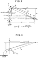
- the arm 3 as shown in Fig. 2 includes a base shaft section 31 swingably supported at the base point 311 as a supporting point and an arm section 33 that is parallel to but slightly deviated from a base line A along the direction of the base shaft of the base shaft section 31 and is formed integrally with the base shaft section 31 through a joint 32 which is orthogonal to the base line A.
- the stylus 4 is formed at the other end opposite to a base end of the arm section 33 to be generally at right angle to the arm section 33.
- the contact point 41 is provided to contact the workpiece 11.
- the stylus 4 is provided in a direction of a circumference of the arc C drawn by the tip of the contact point 41 that moves as the arm 3 swings, and the contact point 41 is so arranged to contact the workpiece 11 along from the direction of a tangent line of the arc C at the other end of the arm section 33.
- the shifter 5 includes an x-slider 51 for swingably supporting the base shaft section 31 and an x-guide shaft 52 for guiding the x-slider 51 in the x-direction (see Fig. 1 ).
- the x-direction is a direction for scanning the workpiece surface. This direction is included within at least the swing plane of the arm 3 and same with the direction of the base line of the base shaft section 31 when the swing angle of the arm 3 is zero
- the first detector 6 is designed to detect displacement of the base point 311 of the arm 3 based on displacement of the x-slider 51 and may be an encoder of photoelectric type, an electric capacitance type, or a magnetic type that detects, for instance, shift distance of the x-slider 51 along the x-guide shaft 52.
- the second detector 7 is designed to detect z-direction displacement of the middle point D at the middle point D of the base shaft section 31 and may be an encoder having, for instance, a movable electrode 71 that moves integrally with the middle point D and a scale 72 that is arranged parallel to the swing plane of the arm 3 and perpendicular to the x-direction for detecting z-direction displacement of the movable electrode 71.
- the z-direction is a direction perpendicular to the x-direction and is included at least within the swing plane of the arm 3.
- the compensation computing unit 8 includes a memory 81 storing a predetermined parameter and a computing section 82 for performing computation according to a predetermined computation formula, and calculates measurement data of the workpiece surface based on the detection results of the first detector 6 and the second detector 7.
- the compensation computing unit 8 also includes a calibration computing section 83, of which operation will be described later, for calibrating each parameter for the memory 81.
- the compensation computing unit 8 obtains the measurement data of the workpiece surface from the detection results of the first detector 6 and the second detector 7 in a following way.
- a reference point P is set for setting a reference length L of the arm 3.
- the reference point P is set at a foot of a perpendicular line extended from the tip of the contact point 41 to the base line A, which is the base shaft of the arm 3, and the arm reference length L is set as the length from the base point 311 (a swing center) to the reference point P in the direction of the base shaft of the arm 3.
- the x-coordinate (the uncompensated x-coordinate) of the reference point P is the same as the detection result of the first detector 6.
- the z-coordinate (the uncompensated z-coordinate) can be calculated with (the detection value z i of the second detector) ⁇ (the arm reference length L) / (the length Lo from the base point to the middle point), where Lo is the length from the base point 311 to the middle point D (a detection point of the second detector). Accordingly, when the detection value of the second detector 7 is z i , the z-coordinates of the reference point P can be found as gz i by using a predetermined gain "g".
- the x-coordinate (the uncompensated x-coordinate) of the reference point P with the swing angle of the arm 3 being zero is found based on the detection result of the first detector 6, and the gz i (the uncompensated z-coordinate) as the z-coordinate of the reference point P with the detection result of the second detector 7 being z i is found.
- the coordinates of the contact point 41 are obviously deviated from the uncompensated x-coordinate and the uncompensated z-coordinate, it is necessary to find compensation amount for each of the x-coordinate and the y-coordinate for compensating for these deviations at the next step.
- the length from the reference point P to the tip of the contact point 41 is tip compensation amount "h".
- the detection value of the second detector 7 is z i .
- the deviation (the z-direction compensation amount) between the z-coordinate of the contact point 41 and the uncompensated z-coordinate is represented by the following formula.
- the reference point P is found based in the detection results of the first detector 6 and the second detector 7 and then the deviations derived from the above formulas (5) and (6) are counted in, so that the coordinates of the contact point 41 are found.
- the memory 81 of the compensation computing unit 8 stores an arm reference length L, a gain "g", and a tip compensation amount "h” which are set as default. Otherwise, the memory 81 stores arm reference length L, predetermined gain "g", tip compensation amount "h” which are calibrated in a previous calibration.
- the computing section 82 performs the computation of the formulas (5) and (6) using the detection results of the first detector 6 and the second detector 7 and the parameters stored in the memory 81 to find the coordinates of the contact point 41.
- the computing section 82 counts the tip radius of the contact point 41, the contact angle of the contact point to the workpiece surface, and the z-coordinate of the reference point P with the base shaft of the arm 3 (the base line A) being parallel to the x-direction (or, zeroset deviation which is the value derived by multiplying the detection result of the second detector 7 by the gain "g" in this condition) in the detection results to obtain the measurement data of the workpiece surface.
- the workpiece 11 is placed on the stage 2, and the workpiece surface is contacted by the contact point 41.
- the shifter 5 shifts the arm 3 in the x-direction while the first detector 6 and the second detector 7 perform detection at every predetermined shift distance interval in the x-direciton.
- the detection results of the first detector 6 and the second detector 7 are sent to the compensation computing unit 8, so that the computing section 82 performs the computation to find the measurement data of the workpiece surface.
- the measurement data is displayed on the display 9 to find the surface texture of the workpiece surface.
- the calibration method for the surface texture measuring instrument 1 includes a measurement step for measuring a calibration gauge 10 of which cross section contains a part of a substantially perfect circle, an assignment step for assigning the detection results of the first detector 6 and the second detector 7, which are obtained in the measurement step, in an evaluation formula based on a circle equation in which the center coordinates of the perfect circle are (x c , z c ) and the radius is "r", and a calibration step for applying least square method to the evaluation formula obtained in the assignment step to calibrate each parameter included in the deviation.
- a measurement is performed on a calibration gauge 10 of which cross section taken parallel to the x-direction can be regarded as a perfect circle.
- the detection results of the first detector 6 and the second detector 7 in the measurement step as calibration data sent to and stored in the calibration computing section 83.
- the calibration computing section 83 assigns the stored calibration data in the evaluation formula based on the circle equation (the assignment step).
- the surface coordinates of the calibration gauge 10 resulted from the compensation computation of the computing section 82 may be assigned. However, if simplification as described below is included, calculation load can be reduced in the subsequent calibration step.
- the tip radius of the contact point 41 when the tip section of the contact point 41 is regarded as a perfect sphere, only the radius of the contact point 41 offsets against the radius of the calibration gauge 10. Therefore, the circle equitation is satisfied without counting the radius of the contact point 41 in the calibration data. For this reason, when the calibration data is assigned in the evaluation formula, the radius of the contact point 41 will not be counted in.
- the value of the x-coordinate is X i which is found by counting the deviation dx due to the swing of the arm 3 (see the formula (5)) in the detection result x i of the first detector 6.
- the value of the z-coordinate is Z i which is found by counting the deviation dz due to the swing of the arm 3 (see the formula (6)) in the z-coordinate gz i of the reference point P.
- the least square method is applied to the above evaluation formula (8).
- the center coordinates (x c , z c ), the radius "r”, the gain "g”, and the tip compensation amount "h” are subjected to the calibration.
- the result can be obtained by adding the calculation results of the above formula (9), ⁇ x c , ⁇ z c , ⁇ g, ... ⁇ r to default values of each parameter.
- the calculation may be repeated to make the resulted value of the above formula small enough to improve the calculation accuracy.
- each parameter stored in the memory 8 is calibrated based on the calculation result obtained with the use of the least square method in the calibration step. Then, the calibrated parameters are applied to the detection values of the first detector and the second detector, so that the measurement result of the workpiece surface is obtained at the computing section 82.
- the calibration gauge 10 of which cross section can be regarded as a substantially perfect circle is measured and the least square method based on the circle equation is applied to this measurement result, a plurality of parameters can be calibrated with one measurement. That is, the calibration is simple since it is unnecessary to perform the measurement and the calibration computation for calibrating the gain "g" and further perform the measurement and the calibration computation for calibrating the tip compensation amount "h". In addition, since the calibration requires only one calibration gauge 10, the cost can be reduced.
- the calibrated surface texture measuring instrument can accurately measure the workpiece surface avoiding a symmetry error which is a measurement value difference between a workpiece surface measured in pulse x-direction (an ascending direction) and the same surface measured in minus x-direction (a descending direction)
- the second embodiment is characterized in that the arm reference length L is also subjected to the calibration in addition to those subjected to the calibration in the first embodiment in applying the least square method.
- the arm reference length L can be calibrated in addition to the advantages of the first embodiment.
- the present embodiment allows the calibration of the arm reference length L even when the arm 3 is replaced.
- the calibration of the arm reference length L further improves the measurement accuracy of the workpiece surface texture.
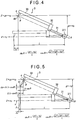
- the third embodiment is characterized in that the arm reference length L and the zeroset deviation z 0 are also subjected to the calibration in addition to those subjected to the calibration in the first embodiment.
- the contact point 41 is arranged to generally match the reference point.
- the tip compensation amount "h" is approximately zero
- the deviation due to the swing of the arm 3 is represented by the below formula that corresponds to the formulas (5) and (6).
- the zeroset deviation of the second detector is counted in.
- the zeroset deviation z 0 is the value of the z-coordinate of the contact point 41 (the reference point P) with the base shaft of the arm 3 (the base line A) being parallel to the x-direction (or, the value derived by multiplying the detection result of the second detector 7 by the gain "g" in this condition).
- L dz 0
- the value of the x-coordinate is X i which is found by counting the deviation dx due to the swing of the swing arm 3 (see the formula (11)) in the detection result x i of the first detector 6.
- the value of the z-coordinate is Z i which is the z-coordinate gz i of the reference point P (the contact point 41). It is noted that the offset due to the radius of the contact point 41 and the zeroset deviation in the x-direction are disregarded.
- X i x i + L 1 ⁇ L 2 ⁇ g z i ⁇ z O 2
- L Z i g z i
- the center coordinates (x c , z c ), the radius "r”, the gain "g”, the zeroset deviation z 0 , and the arm reference length L are subjected to the calibration.
- the zeroset deviation z 0 can be calibrated in addition to the advantages of the above embodiments. Therefore, in the arrangement where the contact point 41 generally matches the reference point P, even if the adjustment for setting the contact point 41 to match the reference point P or the adjustment for setting the detection result of the second detector to zero with the base shaft of the arm 3 (the base line A) being parallel to the x-direction, are inaccurate and hence resulted in a little adjustment error, the zeroset deviation z 0 can be calibrated in the present embodiment. Consequently, the work for adjusting the position of the contact point 41 and the zeroset of the second detector 7 can be simplified while accurate measurement can be performed.
- the fourth embodiment is characterized in that the arm reference length L and the zeroset deviation z 0 are also subjected to the calibration in addition to those subjected to the calibration in the first embodiment.
- the zeroset deviation z 0 is the value of the z-coordinate of the reference point P with the base shaft of the arm 3 (the base line A) being parallel to the x-direction (or, the value derived by multiplying the detection result of the second detector 7 by the gain "g" in this condition).
- the deviation due to the swing of the arm 3 is represented by the below formula that corresponds to the formulas (5) and (6).
- the x-coordinate is X i which is found by counting the deviation dx due to the swing of the swing arm 3 (see the formula (15)) in the detection result x i of the first detector 6.
- the value of the z-coordinate is Z i which is found by counting the deviation dz due to the swing of the arm 3 (see the formula (15)) in the z-coordinate gz i of the reference point P. It is noted that the offset due to the radius of the contact point 41 and the tip compensation amount "h" are disregarded.
- the center coordinates (x c , z c ), the radius "r”, the gain "g”, the zeroset deviation z 0 , and the arm reference length L are subjected to the calibration.
- the present invention is not limited to the above-described embodiments, but includes various modifications as long as the object of the present invention can be achieved.
- the shape of the arm and the stylus is not limited to the linear shape, but may be a curved shape. Any shape may be applicable as far as the base end is swingably supported, the contact point contacts the workpiece from the direction of the tangent line of the arc, and the texture of the workpiece surface is measured based on the shift distance of the base end and the swing amount of the arm.
- the calibration may be performed on the radius of the contact point. That is, if the radius of the calibration gauge is known, the radius of the contact point can be found by subtracting the radius of the calibration gauge from the radius obtained with the use of the least square method.
- the surface texture measuring instrument is a contact type instrument of which contact point contacts and scans on the workpiece in the above description
- a non-contact type contact point may be used. Even in this case, as long as the radius of the calibration gauge is known, the deviation of the contact point can be calibrated.
- the least square method is used as a solving method for finding each parameter based on the evaluation formula, it may be substituted by other solving methods.
- the second detector 7 is arranged between the base point 311 (the swing center) and the reference point P in the described embodiments.
- the base shaft section 31 may be extended to the right side of the base point 311 (the swing center) and the second detector 7 may be arranged at the right side of the base point 311 (the swing center) in Fig. 1 as an example.
- Such configuration can be considered the same as those presented in the above embodiments except for the fact that the detection value of the second detector 7 has the sign opposite to that of the above embodiments.
- the gain “g” is determined based on the arm reference length L and the length Lo from the base point to the middle point in the above embodiments, the gain “g” may be calibrated as a total gain “g” in which other variations (e.g. the reference length L, the angularity of the detector, the temperature. etc) are counted.
- a second calibration step may be provided, by giving a true shape of the calibration gauge, for calculating the tip shape of the contact point based on the difference from the radius "r" found in the calibration step. Accordingly, since the true shape of the calibration gauge is given, the tip shape of the contact point can be found based on the difference from the radius "r" found in the calibration step.
- the shape of the calibration gauge and the tip shape of the contact point are typically spherical, they are not exactly perfect spheres.
- lengths from the nominal center of the sphere (x c , z c ) to the sphere surface in each angle direction are not necessarily the same. Therefore, the lengths from the nominal center of the calibration gauge to the sphere surface in respective angle direction are measured in advance. Then the lengths in each angle direction corresponding to the detection results in the measurement step are calculated and the difference from the radius "r" found in the calibration step is found. In this way, even when the calibration gauge is not perfect sphere, accurate calibration calculation can be performed.
- the tip shape of the contact point based on the angle corresponding to the detection result in the measurement step (measurement orientation of contact section and the like of the contact point with the calibration gauge seen from the nominal center of the contact point) and the true shape of the calibration gauge, the length from the nominal center of the contact point to the surface of the contact point at the corresponding angle (measurement orientation) can be found (The distance is found as the difference between the radius "r" at each angle found in the calibration step and the length of a corresponding section of the calibration gauge). Accordingly, if a specific area of the spherical calibration gauge is measured and the contact point is measured at each measurement orientation, the lengths at each measurement orientation can be found and therefore the tip shape of the contact point can be found.
- a computer having a CPU (Central Processing Unit) and a memory (storage unit) may be built in the surface texture measuring instrument while arranging a program so that a computer executes each step of the calibration method described in the above embodiments.
- the program may be stored in a recording medium and be installed in a computer by directly inserting the recording medium to the computer, or alternatively, a reader device may be externally attached to the computer to install the program in the computer through the reader device.
- the program may be supplied and installed to the computer wirelessly or through a communication line such as the Internet, LAN cable and telephone line.
Claims (9)
- Procédé de calibration d'un instrument de mesure de texture de surface (1) qui mesure une surface d'une pièce d'usinage (11), l'instrument (1) comprenant: un bras (3) supporté pour pouvoir pivoter autour d'un point de base (311), un stylet (4) agencé sur une extrémité du bras (3) et muni d'un point de contact (41) sur son extrémité, le point de contact (41) étant en contact ou presque au contact de la pièce d'usinage (11) le long d'une ligne plus ou moins tangentielle d'un arc (C) tracé par une pointe du point de contact (41) en fonction d'un mouvement du bras (3); un dispositif de décalage (5) pour déplacer le bras (3) dans la direction x qui longe la surface de la pièce d'usinage tout en gardant le point de contact (41) en contact ou presque au contact de la surface de la pièce d'usinage; un premier détecteur (6) pour détecter un déplacement du point de base (311) dans la direction x; un second détecteur (7) pour détecter un déplacement dans la direction z qui est orthogonal à la direction x du fait du basculement du bras (3) sur la base d'un déplacement d'un point (D) sur le bras (3) dans la direction z; et une unité de calcul de compensation (8) qui compense les résultats de détection (xi) du premier détecteur (6) et les résultats de détection sous la forme d'un premier déplacement (zi) du second détecteur (7) en fonction d'un écart (dx, dz) provoqué par le basculement pour obtenir des données de mesure de la surface de la pièce d'usinage (11),
le procédé comprenant:une étape de mesure pour mesurer une jauge de calibration (10) dont la section transversale contient une partie d'un cercle sensiblement parfait;une étape d'affectation pour affecter les résultats de détection (xi) du premier détecteur (6) et du premier déplacement (zi) sous la forme des résultats de détection du second détecteur (7), qui sont obtenus à l'étape de mesure, dans une formule d'évaluation (fi) fondée sur une équation de cercle dans laquelle les coordonnées centrales de la jauge de calibration (10) sont (xc, zc) et un rayon de la jauge de calibration (10) est r; etune étape de calibration pour calibrer un gain (g) afin de convertir le premier déplacement (Zj) du point (D) sur le bras (3) dans la direction z détectée par le second détecteur (7) en un second déplacement de la pointe du point de contact (41) dans la direction z, et chaque paramètre inclus dans l'écart (dx, dz) sur la base des résultats obtenus dans l'étape d'affectation,dans lequel la formule d'évaluation (fi) dans l'étape d'affectation est déterminée sur la base: d'une longueur de référence de bras (L) comme longueur allant du point de base (311) à un point de référence (P) comme pied d'une ligne perpendiculaire s'étendant de l'extrémité du point de contact (41) jusqu'à une ligne de base (A) s'étendant dans la direction longitudinale d'un arbre de base (31) du bras (3); d'une valeur de détection (xi) du premier détecteur (6); du premier déplacement (zi); du gain (g); et d'une quantité de compensation de pointe (h) comme longueur allant du point de référence (P) jusqu'à l'extrémité du point de contact (41), etdans lequel, la longueur de référence de bras connue (L) étant donnée, les coordonnées de centre (xc, zc), le rayon (r), le gain (g) et la quantité de compensation de pointe (h) sont définis dans l'étape de calibrage. - Procédé de calibration d'un instrument de mesure de texture de surface (1) qui mesure une surface d'une pièce d'usinage (11), l'instrument (1) comprenant: un bras (3) supporté pour pouvoir pivoter autour d'un point de base (311); un stylet (4) agencé sur une extrémité du bras (3) et muni d'un point de contact (41) sur son extrémité, le point de contact (41) étant en contact ou presque au contact de la pièce d'usinage (11) le long d'une ligne plus ou moins tangentielle d'un arc (C) tracé par une pointe du point de contact (41) en fonction d'un mouvement du bras (3); un dispositif de décalage (5) pour déplacer le bras (3) dans la direction x qui longe la surface de la pièce d'usinage tout en gardant le point de contact (41) en contact ou presque au contact de la surface de la pièce d'usinage; un premier détecteur (6) pour détecter un déplacement du point de base (311) dans la direction x; un second détecteur (7) pour détecter un déplacement dans la direction z qui est orthogonal à la direction x du fait du basculement du bras (3) sur la base d'un déplacement d'un point (D) sur le bras (3) dans la direction z; et une unité de calcul de compensation (8) qui compense les résultats de détection (xi) du premier détecteur (6) et les résultats de détection sous la forme d'un premier déplacement (zi) du second détecteur (7) en fonction d'un écart (dx, dz) provoqué par le basculement pour obtenir des données de mesure de la surface de la pièce d'usinage (11),
le procédé comprenant:une étape de mesure pour mesurer une jauge de calibration (10) dont la section transversale contient une partie d'un cercle sensiblement parfait;une étape d'affectation pour affecter les résultats de détection (xi) du premier détecteur (6) et du premier déplacement (zi) sous forme des résultats de détection du second détecteur (7), qui sont obtenus dans l'étape de mesure, dans un formule d'évaluation (fi) fondée sur une équation de cercle dans laquelle les coordonnées du centre de la jauge de calibration (10) sont (xc, zc) et un rayon de la jauge de calibration (10) est r; etune étape de calibration pour calibrer un gain (g) afin de convertir le premier déplacement (zi) du point (D) sur le bras (3) dans la direction z détectée par le second détecteur (7) en un second déplacement de la pointe du point de contact (41) dans la direction z, et chaque paramètre inclus dans l'écart (dx, dz) sur la base des résultats obtenus dans l'étape d'affectation,dans lequel la formule d'évaluation (fi) dans l'étape d'affectation est déterminée sur la base: d'une longueur de référence de bras (L) comme longueur allant du point de base (311) à un point de référence (P) comme pied d'une ligne perpendiculaire s'étendant de l'extrémité du point de contact (41) jusqu'à une ligne de base (A) s'étendant dans la direction longitudinale d'un arbre de base (31) du bras (3); des résultats de détection (xi) du premier détecteur (6); du premier déplacement (Zi); du gain (g); et de l'écart défini sur zéro (zo) comme valeur obtenue en multipliant le premier déplacement, qui est obtenu lorsque l'arbre de base (31) du bras (3) est parallèle à la direction x, par le gain (g), etdans lequel les coordonnées de centre (xc, zc) du cercle, le rayon (r) du cercle, le gain (g), la longueur de référence de bras (L) et l'écart réglé sur zéro (z0) sont définis. - Procédé selon la revendication 2,
dans lequel la formule d'évaluation (fi) dans l'étape d'affectation est déterminée sur la base: d'une longueur de référence de bras (L); d'une valeur de détection (xi) du premier détecteur (6); du premier déplacement (zi); du gain (g); d'une quantité de compensation de pointe (h) comme longueur allant du point de référence (P) jusqu'à l'extrémité du point de contact (41), et de l'écart réglé sur zéro (zo), et
dans lequel les coordonnées de centre xc, zc) du cercle, le rayon (r) du cercle, la quantité de compensation de pointe (h), le gain (g), l'écart réglé sur zéro (z0) et la longueur de référence de bras (L) sont définis. - Procédé selon l'une quelconque des revendications 1 à 3, comprenant en outre une seconde étape de calibration, avec une vraie forme de la jauge de calibration (10) étant donnée, pour calculer une forme de pointe du point de contact (41) en fonction de la différence par rapport au rayon (r) trouvée dans l'étape de calibration.
- Procédé selon la revendication 4, dans lequel la jauge de calibration (10) contient au moins une partie d'un cercle parfait et la vraie forme de la jauge de calibration (10) est représentée par un rayon (rt) du cercle parfait.
- Procédé selon la revendication 4, dans lequel la forme de pointe du point de contact (41) contient au moins une partie d'un cercle parfait et est représentée par le rayon du cercle parfait.
- Programme pour un instrument de mesure de texture de surface (1) dans lequel un ordinateur exécute le procédé de calibration pour l'instrument de mesure de surface (1) selon l'une quelconque des revendications 1 à 6.
- Support d'enregistrement lisible par ordinateur stockant le programme selon la revendication 7.
- Instrument de mesure de texture de surface comprenant le programme selon revendication 7, le programme étant exécutable par un ordinateur.
Applications Claiming Priority (2)
| Application Number | Priority Date | Filing Date | Title |
|---|---|---|---|
| JP2003129882A JP4323212B2 (ja) | 2003-05-08 | 2003-05-08 | 表面性状測定機の校正方法、表面性状測定機の校正プログラム、この校正プログラムを記録した記録媒体および表面性状測定機 |
| JP2003129882 | 2003-05-08 |
Publications (3)
| Publication Number | Publication Date |
|---|---|
| EP1475603A2 EP1475603A2 (fr) | 2004-11-10 |
| EP1475603A3 EP1475603A3 (fr) | 2011-07-06 |
| EP1475603B1 true EP1475603B1 (fr) | 2018-09-19 |
Family
ID=32985644
Family Applications (1)
| Application Number | Title | Priority Date | Filing Date |
|---|---|---|---|
| EP04010601.5A Expired - Fee Related EP1475603B1 (fr) | 2003-05-08 | 2004-05-04 | Procédé de calibration pour un instrument pour mesurer la texture d'une surface et ledit instrument |
Country Status (4)
| Country | Link |
|---|---|
| US (1) | US7162383B2 (fr) |
| EP (1) | EP1475603B1 (fr) |
| JP (1) | JP4323212B2 (fr) |
| CN (1) | CN100371672C (fr) |
Families Citing this family (57)
| Publication number | Priority date | Publication date | Assignee | Title |
|---|---|---|---|---|
| JP2005055282A (ja) * | 2003-08-04 | 2005-03-03 | Tokyo Seimitsu Co Ltd | 測定方法及び測定装置 |
| US7519502B1 (en) * | 2003-09-05 | 2009-04-14 | The United States Of America As Represented By The Secretary Of The Navy | Surface profile measurement processing method |
| JP4694881B2 (ja) * | 2005-01-05 | 2011-06-08 | 株式会社ミツトヨ | 不確かさ推定方法及びプログラム |
| GB2429291B (en) * | 2005-08-18 | 2008-08-20 | Taylor Hobson Ltd | A metrological apparatus |
| JP4372759B2 (ja) * | 2006-02-10 | 2009-11-25 | 株式会社ミツトヨ | 形状測定装置、形状測定方法及び形状測定プログラム |
| US9352411B2 (en) | 2008-05-28 | 2016-05-31 | Illinois Tool Works Inc. | Welding training system |
| CN101520296B (zh) * | 2008-12-30 | 2011-12-28 | 惠阳航空螺旋桨有限责任公司 | 一种圆周均布孔位置度误差的三坐标测量方法 |
| JP5464943B2 (ja) * | 2009-08-19 | 2014-04-09 | オリンパス株式会社 | 表面性状を測定する測定機の性能評価に用いられる標準片 |
| CN102168959B (zh) * | 2010-02-26 | 2012-11-28 | 中国海洋石油总公司 | 三维坐标系下检测导管架各圆形杆件空间位置状态的方法 |
| CN101936699B (zh) * | 2010-08-24 | 2012-04-18 | 中国科学院光电技术研究所 | 摆臂式三维轮廓仪 |
| US9101994B2 (en) | 2011-08-10 | 2015-08-11 | Illinois Tool Works Inc. | System and device for welding training |
| CN102814512B (zh) * | 2012-08-24 | 2014-07-16 | 沈阳黎明航空发动机(集团)有限责任公司 | 一种针对发动机压气机盘类零件辐板型面的在线测量方法 |
| US9583014B2 (en) | 2012-11-09 | 2017-02-28 | Illinois Tool Works Inc. | System and device for welding training |
| US9368045B2 (en) | 2012-11-09 | 2016-06-14 | Illinois Tool Works Inc. | System and device for welding training |
| US9583023B2 (en) | 2013-03-15 | 2017-02-28 | Illinois Tool Works Inc. | Welding torch for a welding training system |
| US9728103B2 (en) | 2013-03-15 | 2017-08-08 | Illinois Tool Works Inc. | Data storage and analysis for a welding training system |
| US9672757B2 (en) | 2013-03-15 | 2017-06-06 | Illinois Tool Works Inc. | Multi-mode software and method for a welding training system |
| US9713852B2 (en) | 2013-03-15 | 2017-07-25 | Illinois Tool Works Inc. | Welding training systems and devices |
| US9666100B2 (en) | 2013-03-15 | 2017-05-30 | Illinois Tool Works Inc. | Calibration devices for a welding training system |
| CN103575244B (zh) * | 2013-11-11 | 2015-12-02 | 西安工业大学 | 极坐标齿轮测量中心测头偏置量的自动校正方法 |
| US10056010B2 (en) | 2013-12-03 | 2018-08-21 | Illinois Tool Works Inc. | Systems and methods for a weld training system |
| US10105782B2 (en) | 2014-01-07 | 2018-10-23 | Illinois Tool Works Inc. | Feedback from a welding torch of a welding system |
| US9724788B2 (en) | 2014-01-07 | 2017-08-08 | Illinois Tool Works Inc. | Electrical assemblies for a welding system |
| US9751149B2 (en) | 2014-01-07 | 2017-09-05 | Illinois Tool Works Inc. | Welding stand for a welding system |
| US9757819B2 (en) * | 2014-01-07 | 2017-09-12 | Illinois Tool Works Inc. | Calibration tool and method for a welding system |
| US10170019B2 (en) | 2014-01-07 | 2019-01-01 | Illinois Tool Works Inc. | Feedback from a welding torch of a welding system |
| US9589481B2 (en) | 2014-01-07 | 2017-03-07 | Illinois Tool Works Inc. | Welding software for detection and control of devices and for analysis of data |
| JP6254451B2 (ja) * | 2014-02-19 | 2017-12-27 | 株式会社ミツトヨ | 形状測定装置及び形状測定誤差の補正方法 |
| JP6197261B2 (ja) * | 2014-03-14 | 2017-09-20 | 株式会社東京精密 | 測定機の校正方法及びその装置 |
| US10665128B2 (en) | 2014-06-27 | 2020-05-26 | Illinois Tool Works Inc. | System and method of monitoring welding information |
| US10307853B2 (en) | 2014-06-27 | 2019-06-04 | Illinois Tool Works Inc. | System and method for managing welding data |
| US9862049B2 (en) | 2014-06-27 | 2018-01-09 | Illinois Tool Works Inc. | System and method of welding system operator identification |
| US9937578B2 (en) | 2014-06-27 | 2018-04-10 | Illinois Tool Works Inc. | System and method for remote welding training |
| US11014183B2 (en) | 2014-08-07 | 2021-05-25 | Illinois Tool Works Inc. | System and method of marking a welding workpiece |
| US9724787B2 (en) | 2014-08-07 | 2017-08-08 | Illinois Tool Works Inc. | System and method of monitoring a welding environment |
| US9875665B2 (en) | 2014-08-18 | 2018-01-23 | Illinois Tool Works Inc. | Weld training system and method |
| US10239147B2 (en) | 2014-10-16 | 2019-03-26 | Illinois Tool Works Inc. | Sensor-based power controls for a welding system |
| US11247289B2 (en) | 2014-10-16 | 2022-02-15 | Illinois Tool Works Inc. | Remote power supply parameter adjustment |
| US10402959B2 (en) | 2014-11-05 | 2019-09-03 | Illinois Tool Works Inc. | System and method of active torch marker control |
| US10490098B2 (en) | 2014-11-05 | 2019-11-26 | Illinois Tool Works Inc. | System and method of recording multi-run data |
| US10417934B2 (en) | 2014-11-05 | 2019-09-17 | Illinois Tool Works Inc. | System and method of reviewing weld data |
| US10204406B2 (en) | 2014-11-05 | 2019-02-12 | Illinois Tool Works Inc. | System and method of controlling welding system camera exposure and marker illumination |
| US10373304B2 (en) | 2014-11-05 | 2019-08-06 | Illinois Tool Works Inc. | System and method of arranging welding device markers |
| US10210773B2 (en) | 2014-11-05 | 2019-02-19 | Illinois Tool Works Inc. | System and method for welding torch display |
| JP6447997B2 (ja) * | 2015-02-09 | 2019-01-09 | 株式会社ミツトヨ | テストインジケータ |
| US10427239B2 (en) | 2015-04-02 | 2019-10-01 | Illinois Tool Works Inc. | Systems and methods for tracking weld training arc parameters |
| DE102015209193A1 (de) | 2015-05-20 | 2016-11-24 | Carl Zeiss Industrielle Messtechnik Gmbh | Verfahren zur Erfassung dynamischer Schwingungen eines Rauheitssensors, Verfahren zur Vermessung der Rauheit einer Werkstückoberfläche, Computerprogrammprodukt sowie Messgerät eingerichtet zur Durchführung der Verfahren. |
| US10593230B2 (en) | 2015-08-12 | 2020-03-17 | Illinois Tool Works Inc. | Stick welding electrode holder systems and methods |
| US10438505B2 (en) | 2015-08-12 | 2019-10-08 | Illinois Tool Works | Welding training system interface |
| US10373517B2 (en) | 2015-08-12 | 2019-08-06 | Illinois Tool Works Inc. | Simulation stick welding electrode holder systems and methods |
| US10657839B2 (en) | 2015-08-12 | 2020-05-19 | Illinois Tool Works Inc. | Stick welding electrode holders with real-time feedback features |
| DE102017103938A1 (de) * | 2017-02-24 | 2018-08-30 | Carl Zeiss Industrielle Messtechnik Gmbh | Vorrichtung zum Messen der Rauheit einer Werkstückoberfläche |
| CN106940178A (zh) * | 2017-03-22 | 2017-07-11 | 上海日进机床有限公司 | 硅晶体工件平整度检测装置和硅晶体工件平整度检测方法 |
| JP7032994B2 (ja) * | 2018-05-08 | 2022-03-09 | Dgshape株式会社 | 補正装置および補正方法 |
| US11776423B2 (en) | 2019-07-22 | 2023-10-03 | Illinois Tool Works Inc. | Connection boxes for gas tungsten arc welding training systems |
| US11288978B2 (en) | 2019-07-22 | 2022-03-29 | Illinois Tool Works Inc. | Gas tungsten arc welding training systems |
| JP7280772B2 (ja) | 2019-07-29 | 2023-05-24 | 株式会社ミツトヨ | 表面性状測定装置のパラメータ校正方法 |
Family Cites Families (8)
| Publication number | Priority date | Publication date | Assignee | Title |
|---|---|---|---|---|
| US5491904A (en) * | 1990-02-23 | 1996-02-20 | Mcmurtry; David R. | Touch probe |
| DE4238139C2 (de) * | 1992-11-12 | 2002-10-24 | Zeiss Carl | Koordinatenmeßgerät |
| JP2727067B2 (ja) | 1995-06-13 | 1998-03-11 | 株式会社ミツトヨ | 形状測定機 |
| JP3215325B2 (ja) | 1996-06-07 | 2001-10-02 | 株式会社東京精密 | 測定機の校正方法及びその装置 |
| JP3215354B2 (ja) | 1997-06-04 | 2001-10-02 | 株式会社東京精密 | 測定機の校正方法及びその装置 |
| GB9907644D0 (en) * | 1999-04-06 | 1999-05-26 | Renishaw Plc | Surface sensing device with optical sensor |
| JP3516630B2 (ja) | 2000-03-29 | 2004-04-05 | 株式会社ミツトヨ | 形状測定機及び形状測定方法 |
| US7036238B2 (en) * | 2003-12-22 | 2006-05-02 | Mitutoyo Corporation | Width-measuring method and surface texture measuring instrument |
-
2003
- 2003-05-08 JP JP2003129882A patent/JP4323212B2/ja not_active Expired - Fee Related
-
2004
- 2004-04-28 US US10/833,007 patent/US7162383B2/en active Active
- 2004-05-04 EP EP04010601.5A patent/EP1475603B1/fr not_active Expired - Fee Related
- 2004-05-08 CN CNB2004100381226A patent/CN100371672C/zh not_active Expired - Fee Related
Non-Patent Citations (1)
| Title |
|---|
| None * |
Also Published As
| Publication number | Publication date |
|---|---|
| CN100371672C (zh) | 2008-02-27 |
| JP4323212B2 (ja) | 2009-09-02 |
| US7162383B2 (en) | 2007-01-09 |
| JP2004333312A (ja) | 2004-11-25 |
| CN1550748A (zh) | 2004-12-01 |
| EP1475603A3 (fr) | 2011-07-06 |
| US20040223148A1 (en) | 2004-11-11 |
| EP1475603A2 (fr) | 2004-11-10 |
Similar Documents
| Publication | Publication Date | Title |
|---|---|---|
| EP1475603B1 (fr) | Procédé de calibration pour un instrument pour mesurer la texture d'une surface et ledit instrument | |
| US7131207B2 (en) | Workpiece inspection method | |
| EP1086356B1 (fr) | Procede d'etalonnage d'un systeme de balayage | |
| JP3005681B1 (ja) | Cmm校正ゲージ及びcmmの校正方法 | |
| US7254506B2 (en) | Method of calibrating a scanning system | |
| JP5823306B2 (ja) | 表面性状測定機の校正方法 | |
| US7318284B2 (en) | Method of calibrating a scanning system | |
| US6453730B2 (en) | Surface texture measuring instrument, surface texture measuring method and stylus radius measuring instrument | |
| EP3346228B1 (fr) | Dispositif de mesure de forme | |
| CN105473981A (zh) | 接触式探针的校准 | |
| GB2288463A (en) | Measuring conical threads | |
| US7117110B2 (en) | Measuring method and measuring apparatus | |
| US7539586B2 (en) | Correction method and measuring instrument | |
| JP4323267B2 (ja) | 形状測定装置、形状測定方法、形状解析装置、形状解析プログラムおよび記録媒体 | |
| JP4098649B2 (ja) | 表面性状測定機の校正用治具、表面性状測定機の校正方法、表面性状測定機の校正プログラムおよびこの校正プログラムを記録した記録媒体 | |
| US9664604B2 (en) | Measurement apparatus, measurement method, and method of manufacturing article | |
| JP7296334B2 (ja) | 真直度計測システム、変位センサ校正方法、及び真直度計測方法 | |
| Ouyang et al. | Ball array calibration on a coordinate measuring machine using a gage block | |
| JP6197261B2 (ja) | 測定機の校正方法及びその装置 | |
| JP2003232625A (ja) | 真直度測定法 | |
| KR200182165Y1 (ko) | 구멍 깊이 측정값의 신뢰성을 향상시킨 계측장비 |
Legal Events
| Date | Code | Title | Description |
|---|---|---|---|
| PUAI | Public reference made under article 153(3) epc to a published international application that has entered the european phase |
Free format text: ORIGINAL CODE: 0009012 |
|
| AK | Designated contracting states |
Kind code of ref document: A2 Designated state(s): AT BE BG CH CY CZ DE DK EE ES FI FR GB GR HU IE IT LI LU MC NL PL PT RO SE SI SK TR |
|
| AX | Request for extension of the european patent |
Extension state: AL HR LT LV MK |
|
| PUAL | Search report despatched |
Free format text: ORIGINAL CODE: 0009013 |
|
| AK | Designated contracting states |
Kind code of ref document: A3 Designated state(s): AT BE BG CH CY CZ DE DK EE ES FI FR GB GR HU IE IT LI LU MC NL PL PT RO SE SI SK TR |
|
| AX | Request for extension of the european patent |
Extension state: AL HR LT LV MK |
|
| 17P | Request for examination filed |
Effective date: 20111114 |
|
| AKX | Designation fees paid |
Designated state(s): DE FR GB IT |
|
| 17Q | First examination report despatched |
Effective date: 20120329 |
|
| GRAP | Despatch of communication of intention to grant a patent |
Free format text: ORIGINAL CODE: EPIDOSNIGR1 |
|
| INTG | Intention to grant announced |
Effective date: 20180502 |
|
| GRAS | Grant fee paid |
Free format text: ORIGINAL CODE: EPIDOSNIGR3 |
|
| GRAA | (expected) grant |
Free format text: ORIGINAL CODE: 0009210 |
|
| AK | Designated contracting states |
Kind code of ref document: B1 Designated state(s): DE FR GB IT |
|
| REG | Reference to a national code |
Ref country code: GB Ref legal event code: FG4D |
|
| REG | Reference to a national code |
Ref country code: DE Ref legal event code: R096 Ref document number: 602004053189 Country of ref document: DE |
|
| RIC2 | Information provided on ipc code assigned after grant |
Ipc: G01B 21/30 20060101ALI20040913BHEP Ipc: G01B 21/04 20060101ALI20040913BHEP Ipc: G01B 5/20 20060101ALI20040913BHEP Ipc: G01B 5/28 20060101AFI20040913BHEP Ipc: G01B 21/20 20060101ALI20040913BHEP Ipc: G05B 19/401 20060101ALI20040913BHEP Ipc: G01B 5/008 20060101ALI20040913BHEP |
|
| REG | Reference to a national code |
Ref country code: DE Ref legal event code: R097 Ref document number: 602004053189 Country of ref document: DE |
|
| PLBE | No opposition filed within time limit |
Free format text: ORIGINAL CODE: 0009261 |
|
| STAA | Information on the status of an ep patent application or granted ep patent |
Free format text: STATUS: NO OPPOSITION FILED WITHIN TIME LIMIT |
|
| 26N | No opposition filed |
Effective date: 20190620 |
|
| PGFP | Annual fee paid to national office [announced via postgrant information from national office to epo] |
Ref country code: DE Payment date: 20200520 Year of fee payment: 17 Ref country code: FR Payment date: 20200522 Year of fee payment: 17 |
|
| PGFP | Annual fee paid to national office [announced via postgrant information from national office to epo] |
Ref country code: GB Payment date: 20200527 Year of fee payment: 17 Ref country code: IT Payment date: 20200528 Year of fee payment: 17 |
|
| REG | Reference to a national code |
Ref country code: DE Ref legal event code: R119 Ref document number: 602004053189 Country of ref document: DE |
|
| GBPC | Gb: european patent ceased through non-payment of renewal fee |
Effective date: 20210504 |
|
| PG25 | Lapsed in a contracting state [announced via postgrant information from national office to epo] |
Ref country code: GB Free format text: LAPSE BECAUSE OF NON-PAYMENT OF DUE FEES Effective date: 20210504 Ref country code: DE Free format text: LAPSE BECAUSE OF NON-PAYMENT OF DUE FEES Effective date: 20211201 |
|
| PG25 | Lapsed in a contracting state [announced via postgrant information from national office to epo] |
Ref country code: FR Free format text: LAPSE BECAUSE OF NON-PAYMENT OF DUE FEES Effective date: 20210531 |
|
| PG25 | Lapsed in a contracting state [announced via postgrant information from national office to epo] |
Ref country code: IT Free format text: LAPSE BECAUSE OF NON-PAYMENT OF DUE FEES Effective date: 20200504 |