US20040223148A1 - Calibration method for surface texture measuring instrument, calibration program for surface texture measuring instrument, recording medium storing the calibration program and surface texture measuring instrument - Google Patents

Calibration method for surface texture measuring instrument, calibration program for surface texture measuring instrument, recording medium storing the calibration program and surface texture measuring instrument Download PDF

Info

Publication number
US20040223148A1
US20040223148A1 US10/833,007 US83300704A US2004223148A1 US 20040223148 A1 US20040223148 A1 US 20040223148A1 US 83300704 A US83300704 A US 83300704A US 2004223148 A1 US2004223148 A1 US 2004223148A1
Authority
US
United States
Prior art keywords
detector
calibration
arm
tip
contact point
Prior art date
Legal status (The legal status is an assumption and is not a legal conclusion. Google has not performed a legal analysis and makes no representation as to the accuracy of the status listed.)
Granted
Application number
US10/833,007
Other versions
US7162383B2 (en
Inventor
Isamu Takemura
Current Assignee (The listed assignees may be inaccurate. Google has not performed a legal analysis and makes no representation or warranty as to the accuracy of the list.)
Mitutoyo Corp
Original Assignee
Mitutoyo Corp
Priority date (The priority date is an assumption and is not a legal conclusion. Google has not performed a legal analysis and makes no representation as to the accuracy of the date listed.)
Filing date
Publication date
Application filed by Mitutoyo Corp filed Critical Mitutoyo Corp
Assigned to MITUTOYO CORPORATION reassignment MITUTOYO CORPORATION ASSIGNMENT OF ASSIGNORS INTEREST (SEE DOCUMENT FOR DETAILS). Assignors: TAKEMURA, ISAMU
Publication of US20040223148A1 publication Critical patent/US20040223148A1/en
Application granted granted Critical
Publication of US7162383B2 publication Critical patent/US7162383B2/en
Active legal-status Critical Current
Adjusted expiration legal-status Critical

Links

Images

Classifications

    • GPHYSICS
    • G01MEASURING; TESTING
    • G01BMEASURING LENGTH, THICKNESS OR SIMILAR LINEAR DIMENSIONS; MEASURING ANGLES; MEASURING AREAS; MEASURING IRREGULARITIES OF SURFACES OR CONTOURS
    • G01B5/00Measuring arrangements characterised by the use of mechanical techniques
    • G01B5/28Measuring arrangements characterised by the use of mechanical techniques for measuring roughness or irregularity of surfaces
    • GPHYSICS
    • G01MEASURING; TESTING
    • G01BMEASURING LENGTH, THICKNESS OR SIMILAR LINEAR DIMENSIONS; MEASURING ANGLES; MEASURING AREAS; MEASURING IRREGULARITIES OF SURFACES OR CONTOURS
    • G01B5/00Measuring arrangements characterised by the use of mechanical techniques
    • G01B5/20Measuring arrangements characterised by the use of mechanical techniques for measuring contours or curvatures

Definitions

  • the present invention relates to a calibration method for a surface texture measuring instrument, a calibration program for a surface texture measuring instrument, a recording medium storing the calibration program and a surface texture measuring instrument.
  • a surface texture measuring instrument 1 shown in FIG. 1 has an arm 3 with a base end 311 swingably supported, a contact point 41 that is arranged on the other end of the arm 3 for scanning on a workpiece, a first detector 6 for detecting a displacement of the arm 3 in x-direction and a second detector 7 for detecting the swing of the arm 3 as a displacement in z-direction.
  • the first detector 6 and the second detector 7 are not designed to directly detect the coordinates of the contact point 41 .
  • this circular movement causes a deviation undetectable by a displacement detector such as the first detector 6 and the second detector 7 . Therefore, in a method applied for obtaining measurement data of the workpiece surface by calculating the coordinate of the contact point 41 , the deviation of x-coordinate caused by the circular movement of the arm 3 is defined as dx and that of z-coordinate is defined as dz, and these dx and dz are counted in detection results of the first detector 6 and the second detector 7 .
  • a gauge with a known height is measured to calibrate the deviation in z-direction. Then, a gauge with a known angle or a spherical gauge is measured to calibrate a symmetry error.
  • the z-direction calibration and the subsequent symmetry calibration require considerable time and certain skill since the replacement of reference gauge is necessary in the measurements. Moreover, it is troublesome to set gauges one after another for measuring a plurality of gauges.
  • a method proposed in Reference 3 includes a step for measuring a gauge which can be regarded as a substantially perfect circle one time and a step for applying a least-square method that assigns the measurement data in a circle equation, thus enabling a calibration with one measurement and calculation.
  • a parameter subjected to the calibration is limited, it is impossible to perform calibration more accurately.
  • An object of the present invention is to provide a calibration method for a surface texture measuring instrument for easily and highly accurately calibrating a surface texture measuring instrument, its calibration program, a recording medium storing the calibration program and a surface texture measuring instrument.
  • a calibration method for a surface texture measuring instrument that measures a surface of a workpiece, the instrument including: an arm supported to be swingable around a base point; a stylus that is arranged on an end of the arm and is provided with a contact point on a tip thereof, the contact point being in contact or nearly in contact with the workpiece along a substantial tangent line of an arc drawn by a tip of the contact point in accordance with a swing of the arm; a shifter for shifting the arm in x-direction while keeping the contact point in contact or nearly in contact with the workpiece surface; a first detector for detecting a displacement of the base point in the x-direction; a second detector for detecting a displacement in z-direction due to the swing of the arm based on a displacement of a point on the arm in the z-direction; and a compensation computing unit that compensates detection results of the first detector and the second detector for a deviation due to the swing to obtain measurement data of
  • the calibration gauge is measured to obtain measurement data in the measurement step. Since the calibration gauge has a cross section containing a part of a substantially perfect circle and the data for the perfect circle must satisfy the circle equation, the surface texture measuring instrument can be conversely calibrated by calibrating each parameter to satisfy the circle equation. Therefore, in the assignment step, the data obtained in the measurement step is assigned in the evaluation formula based on the circle equation. Then, each parameter is calibrated by, for example, a least square method in the calibration step.
  • the least square method may be applied selectively to a plurality of parameters subjected to calibration.
  • the evaluation formula in the assignment step is determined based on: an arm reference length L as a length from the base point to a reference point as a foot of a perpendicular line extended from the tip of the contact point to a base shaft of the arm extending in longitudinal direction; a detection value x i of the first detector; a detection result z i of the second detector; a gain “g” of the z-coordinate of the tip of the contact point to the detection result z i of the second detector; and a tip compensation amount “h” as a length from the reference point to the tip of the contact point, and with a known arm reference length L being given, the center coordinates (x c , z c ), the radius “r”, the gain “g” and the tip compensation amount “h” are found in the calibration step.
  • the calibration method for the surface texture measuring instrument it is preferable that, based on a designed value of the arm reference length L, the center coordinates (x c , z c ), the radius “r”, the gain “g”, and the tip compensation amount “h” are found in the calibration step.
  • the evaluation formula in the assignment step is determined based on: an arm reference length L as a length from the base point to the tip of the contact point; a detection value x i of the first detector; a detection result z i of the second detector; a gain “g” of the z-coordinate of the tip of the contact point to the detection result z i of the second detector; and a zeroset deviation z 0 as a value derived by multiplying the detection result of the second detector, which is obtained when a line connecting the base point and the tip of the contact point tip is parallel to the x-direction, by the gain “g”, and that the center coordinates (x c , z c ) of the circle, the radius of the circle “r”, the gain “g”, the arm reference length L and the zeroset deviation z 0 are found.
  • the evaluation formula in the assignment step is determined based on: an arm reference length L as a length from the base point to a reference point as a foot of a perpendicular line extended from the tip of the contact point to a base shaft of the arm extending in longitudinal direction; a detection value x i of the first detector; detection result z i of the second detector; a gain “g” of the z-coordinate of the tip of the contact point to the detection result z i of the second detector; a tip compensation amount “h” as a length from the reference point to the tip of the contact point; and a zeroset deviation z 0 as a value derived by multiplying the detection result of the second detector, which is obtained when the base shaft of the arm is parallel to the x-direction, by the gain “g”, and that the center coordinates (x c , z c ) of the circle, the radius of the circle “r”, the tip
  • the gain “g”, the tip compensation amount “h”, the zeroset deviation z 0 , the arm reference length L and the like can be calibrated. Since these parameters are calibrated based on the data obtained in the single measurement in the measurement step, this method is convenient and the calibration can be performed in a short time.
  • the calibration method for the surface texture measuring instrument according to the present invention preferably further includes a second calibration step, with a true shape of the calibration gauge being given, for computing a tip shape of the contact point based on difference from the radius “r” found in the calibration step.
  • the tip shape of the contact point can be found based on the difference from the radius “r” found in the calibration step.
  • the shape of the calibration gauge and the tip shape of the contact point are typically spherical, they are not exactly perfect sphere.
  • lengths from the nominal center (x c , z c ) of the sphere to the sphere surface in each angle direction are not necessarily the same. Therefore, the lengths from the nominal center of the calibration gauge to the sphere surface in each angle direction are measured in advance. Then the lengths in each angle direction corresponding to the detection results in the measurement step are calculated and the difference from the radius “r” found in the calibration step is found. In this way, even when the calibration gauge is not perfect sphere, accurate calibration calculation can be performed.
  • the tip shape of the contact point based on the angle corresponding to the detection result in the measurement step (measurement orientation of contact section and the like of the contact point with the calibration gauge seen from the nominal center of the contact point) and the true shape of the calibration gauge, the length from the nominal center of the contact point to the surface of the contact point at the corresponding angle (measurement orientation) can be found (The distance is found as the difference between the radius “r” at each angle found in the calibration step and the length of a corresponding section of the calibration gauge). Accordingly, if a specific area of the spherical calibration gauge is measured and the contact point is measured at each measurement orientation, the lengths at each measurement orientation can be found and therefore the tip shape of the contact point can be found.
  • the calibration gauge contains at least a part of a perfect circle and the true shape of the calibration gauge is represented by a radius “rt” of the perfect circle.
  • the part of a perfect circle indicates that, for example, in the case that the calibration gauge contains perfect spherical part and the perfect spherical part is measured in the measurement step, the measured cross section defines a part of a perfect circle.
  • the tip shape of the contact point contains at least a part of a perfect circle and is represented by the radius of the perfect circle.
  • the part of a perfect circle indicates that, for example, in the case that the tip shape of the contact point contains perfect spherical part and the calibration gauge is measured by the perfect spherical part in the measurement step, a measurement portion of the contact point defines a part of a perfect circle.
  • the tip radius of the contact point can be found base on the difference from the radius “r” found in the calibration step more easily. Specifically, since the radius “r” is computed as length from a center of an arc of the tip of the contact point to a center of an arc of the reference gauge, the tip radius of the contact point can be found by subtracting a true radius “rt” of the calibration gauge from the radius “r”.
  • the above-described calibration method has no need to replace the reference gauge, excels in convenience, requires less measurement time and less preparation work, eliminates setting errors caused by the replacement of the reference gauge and hence offers accurate calibration, since the tip shape of the contact point is found based on the data obtained in the single measurement in the measurement step.
  • a computer executes the above-described calibration methods for the surface measuring instrument of the present invention.
  • a computer is embedded in a surface texture measuring instrument that measures a surface of a workpiece, the instrument including: an arm supported to be swingable around a base point; a stylus that is arranged on an end of the arm and is provided with a contact point on a tip thereof, the contact point being in contact or nearly in contact with the workpiece along a substantial tangent line of an arc drawn by a swing of the arm; a shifter for shifting the arm in x-direction while keeping the contact point in contact or nearly in contact with the workpiece surface; a first detector for detecting a displacement of the base point in the x-direction; a second detector for detecting a linear displacement in z-direction due to the swing of the arm based on a displacement of a point on the arm in the z-direction; and a compensation
  • Each parameter is, for example, calibrated by applying the least square method to the evaluation formula.
  • a computer-readable recording medium stores the above-described calibration program of the present invention for a surface texture measuring instrument.
  • the recording medium stores a calibration program for a surface texture measuring instrument in which a computer is embedded, the instrument measures a surface of a workpiece and includes: an arm supported to be swingable around a base point; a stylus that is arranged on an end of the arm and is provided with a contact point on a tip thereof, the contact point being in contact or nearly in contact with the workpiece along a substantial tangent line of an arc drawn by a swing of the arm; a shifter for shifting the arm in x-direction while keeping the contact point in contact or nearly in contact with the workpiece surface; a first detector for detecting a displacement of the base point in the x-direction; a second detector for detecting a linear displacement in z-direction due to the swing of the arm based on a displacement of a point on the arm in the z-direction
  • Each parameter is, for example, calibrated by applying the least square method to the evaluation formula.
  • a surface texture measuring instrument includes the above-described calibration program of the present invention for a surface texture measuring instrument.
  • the same advantages in any one of the above aspects of the present invention can be obtained. Further, if a computer having a CPU (Central Processing Unit) and a memory (storage unit) is built in the surface texture measuring instrument while arranging a program so that a computer executes each step, the parameters subjected to calibration, for example, can be easily changed in the calibration process.
  • the program may be stored in a recording medium and be installed in a computer by directly inserting the recording medium to the computer, or alternatively, a reader device may be externally attached to the computer to install the program in the computer through the reader device.
  • the program may be supplied and installed to the computer wirelessly or through a communication line such as the Internet, LAN cable and telephone line.
  • FIG. 1 is an illustration showing configuration of a surface texture measuring instrument
  • FIG. 2 is an illustration showing a geometric relation of a deviation due to a circular movement of an arm in a first embodiment according to a calibration method for the surface texture measuring instrument of the present invention
  • FIG. 3 is an illustration showing a measurement of a calibration gauge
  • FIG. 4 is an illustration showing a geometric relation of a deviation due to a circular movement of an arm in a third embodiment according to a calibration method for the surface texture measuring instrument of the present invention.
  • FIG. 5 is an illustration showing a geometric relation of a deviation due to a circular movement of an arm in a fourth embodiment according to a calibration method for the surface texture measuring instrument of the present invention.
  • the surface texture measuring instrument 1 includes a stage 2 on which a workpiece 11 is placed, an arm 3 supported to be swingable around a base point 311 , a stylus 4 that is arranged on an end of the arm 3 and is provided with a contact point 41 on a tip thereof to contact the workpiece 11 along a substantial tangent line of an arc C formed by the swing, a shifter 5 for shifting the arm 3 in x-direction while keeping the contact point 41 in contact with the workpiece surface, a first detector 6 for detecting a displacement of the base point 311 in the x-direction, a second detector 7 for detecting a displacement in the z-direction due to the swing of the arm 3 based on a displacement of a middle point D of the arm 3 in the z-direction, a compensation computing unit 8 that compensates detection results of the first detector 6 and the second detector 7 for a deviation due to the swing of the arm 3 to obtain measurement data of the workpiece surface, and a display 9
  • the arm 3 as shown in FIG. 2 includes a base shaft section 31 swingably supported at the base point 311 as a supporting point and an arm section 33 that is parallel to but slightly deviated from a base line A along the direction of the base shaft of the base shaft section 31 and is formed integrally with the base shaft section 31 through a joint 32 which is orthogonal to the base line A.
  • the stylus 4 is formed at the other end opposite to a base end of the arm section 33 to be generally at right angle to the arm section 33 .
  • the contact point 41 is provided to contact the workpiece 11 .
  • the stylus 4 is provided in a direction of a circumference of the arc C drawn by the tip of the contact point 41 that moves as the arm 3 swings, and the contact point 41 is so arranged to contact the workpiece 11 along from the direction of a tangent line of the arc C at the other end of the arm section 33 .
  • the shifter 5 includes an x-slider 51 for swingably supporting the base shaft section 31 and an x-guide shaft 52 for guiding the x-slider 51 in the x-direction (see FIG. 1).
  • the x-direction is a direction for scanning the workpiece surface. This direction is included within at least the swing plane of the arm 3 and same with the direction of the base line of the base shaft section 31 when the swing angle of the arm 3 is zero
  • the first detector 6 is designed to detect displacement of the base point 311 of the arm 3 based on displacement of the x-slider 51 and may be an encoder of photoelectric type, an electric capacitance type, or a magnetic type that detects, for instance, shift distance of the x-slider 51 along the x-guide shaft 52 .
  • the second detector 7 is designed to detect z-direction displacement of the middle point D at the middle point D of the base shaft section 31 and may be an encoder having, for instance, a movable electrode 71 that moves integrally with the middle point D and a scale 72 that is arranged parallel to the swing plane of the arm 3 and perpendicular to the x-direction for detecting z-direction displacement of the movable electrode 71 .
  • the z-direction is a direction perpendicular to the x-direction and is included at least within the swing plane of the arm 3 .
  • the compensation computing unit 8 includes a memory 81 storing a predetermined parameter and a computing section 82 for performing computation according to a predetermined computation formula, and calculates measurement data of the workpiece surface based on the detection results of the first detector 6 and the second detector 7 .
  • the compensation computing unit 8 also includes a calibration computing section 83 , of which operation will be described later, for calibrating each parameter for the memory 81 .
  • the compensation computing unit 8 obtains the measurement data of the workpiece surface from the detection results of the first detector 6 and the second detector 7 in a following way.
  • a reference point P is set for setting a reference length L of the arm 3 .
  • the reference point P is set at a foot of a perpendicular line extended from the tip of the contact point 41 to the base line A, which is the base shaft of the arm 3
  • the arm reference length L is set as the length from the base point 311 (a swing center) to the reference point P in the direction of the base shaft of the arm 3 .
  • the x-coordinate (the uncompensated x-coordinate) of the reference point P is the same as the detection result of the first detector 6 .
  • the z-coordinate (the uncompensated z-coordinate) can be calculated with (the detection value z i of the second detector) ⁇ (the arm reference length L)/(the length Lo from the base point to the middle point), where Lo is the length from the base point 311 to the middle point D (a detection point of the second detector). Accordingly, when the detection value of the second detector 7 is z i , the z-coordinates of the reference point P can be found as gz i by using a predetermined gain “g”.
  • the x-coordinate (the uncompensated x-coordinate) of the reference point P with the swing angle of the arm 3 being zero is found based on the detection result of the first detector 6
  • the gz i (the uncompensated z-coordinate) as the z-coordinate of the reference point P with the detection result of the second detector 7 being z i is found.
  • the coordinates of the contact point 41 are obviously deviated from the uncompensated x-coordinate and the uncompensated z-coordinate, it is necessary to find compensation amount for each of the x-coordinate and the y-coordinate for compensating for these deviations at the next step.
  • the length from the reference point P to the tip of the contact point 41 is tip compensation amount “h”.
  • the detection value of the second detector 7 is z i .
  • the deviation (the x-direction compensation amount) between the x-coordinate of the contact point 41 and the uncompensated x-coordinate is represented by the following formula.
  • the deviation (the z-direction compensation amount) between the z-coordinate of the contact point 41 and the uncompensated z-coordinate is represented by the following formula.
  • the reference point P is found based in the detection results of the first detector 6 and the second detector 7 and then the deviations derived from the above formulas (5) and (6) are counted in, so that the coordinates of the contact point 41 are found.
  • the memory 81 of the compensation computing unit 8 stores an arm reference length L, a gain “g”, and a tip compensation amount “h” which are set as default. Otherwise, the memory 81 stores arm reference length L, predetermined gain “g”, tip compensation amount “h” which are calibrated in a previous calibration.
  • the computing section 82 performs the computation of the formulas (5) and (6) using the detection results of the first detector 6 and the second detector 7 and the parameters stored in the memory 81 to find the coordinates of the contact point 41 .
  • the computing section 82 counts the tip radius of the contact point 41 , the contact angle of the contact point to the workpiece surface, and the z-coordinate of the reference point P with the base shaft of the arm 3 (the base line A) being parallel to the x-direction (or, zeroset deviation which is the value derived by multiplying the detection result of the second detector 7 by the gain “g” in this condition) in the detection results to obtain the measurement data of the workpiece surface.
  • the workpiece 11 is placed on the stage 2 , and the workpiece surface is contacted by the contact point 41 .
  • the shifter 5 shifts the arm 3 in the x-direction while the first detector 6 and the second detector 7 perform detection at every predetermined shift distance interval in the x-direciton.
  • the detection results of the first detector 6 and the second detector 7 are sent to the compensation computing unit 8 , so that the computing section 82 performs the computation to find the measurement data of the workpiece surface.
  • the measurement data is displayed on the display 9 to find the surface texture of the workpiece surface.
  • the calibration method for the surface texture measuring instrument 1 includes a measurement step for measuring a calibration gauge 10 of which cross section contains a part of a substantially perfect circle, an assignment step for assigning the detection results of the first detector 6 and the second detector 7 , which are obtained in the measurement step, in an evaluation formula based on a circle equation in which the center coordinates of the perfect circle are (x c , z c ) and the radius is “r”, and a calibration step for applying least square method to the evaluation formula obtained in the assignment step to calibrate each parameter included in the deviation.
  • a measurement is performed on a calibration gauge 10 of which cross section taken parallel to the x-direction can be regarded as a perfect circle.
  • the detection results of the first detector 6 and the second detector 7 in the measurement step as calibration data sent to and stored in the calibration computing section 83 .
  • the calibration computing section 83 assigns the stored calibration data in the evaluation formula based on the circle equation (the assignment step).
  • the surface coordinates of the calibration gauge 10 resulted from the compensation computation of the computing section 82 may be assigned. However, if simplification as described below is included, calculation load can be reduced in the subsequent calibration step.
  • the tip radius of the contact point 41 when the tip section of the contact point 41 is regarded as a perfect sphere, only the radius of the contact point 41 offsets against the radius of the calibration gauge 10 . Therefore, the circle equitation is satisfied without counting the radius of the contact point 41 in the calibration data. For this reason, when the calibration data is assigned in the evaluation formula, the radius of the contact point 41 will not be counted in.
  • the value of the x-coordinate is X i which is found by counting the deviation dx due to the swing of the arm 3 (see the formula (5)) in the detection result x i of the first detector 6 .
  • the value of the z-coordinate is Z i which is found by counting the deviation dz due to the swing of the arm 3 (see the formula (6)) in the z-coordinate gz i of the reference point P.
  • the least square method is applied to the above evaluation formula (8).
  • the center coordinates (x c , z c ), the radius “r”, the gain “g”, and the tip compensation amount “h” are subjected to the calibration.
  • the result can be obtained by adding the calculation results of the above formula (9), ⁇ x c , ⁇ z c , ⁇ g, . . . ⁇ r to default values of each parameter.
  • the calculation may be repeated to make the resulted value of the above formula small enough to improve the calculation accuracy.
  • each parameter stored in the memory 8 is calibrated based on the calculation result obtained with the use of the least square method in the calibration step. Then, the calibrated parameters are applied to the detection values of the first detector and the second detector, so that the measurement result of the workpiece surface is obtained at the computing section 82 .
  • the calibration gauge 10 of which cross section can be regarded as a substantially perfect circle is measured and the least square method based on the circle equation is applied to this measurement result, a plurality of parameters can be calibrated with one measurement. That is, the calibration is simple since it is unnecessary to perform the measurement and the calibration computation for calibrating the gain “g” and further perform the measurement and the calibration computation for calibrating the tip compensation amount “h”. In addition, since the calibration requires only one calibration gauge 10 , the cost can be reduced.
  • the calibration is simple, measurements can be performed by a surface texture measuring instrument which is always correctly calibrated. Specifically, the calibrated surface texture measuring instrument can accurately measure the workpiece surface avoiding a symmetry error which is a measurement value difference between a workpiece surface measured in pulse x-direction (an ascending direction) and the same surface measured in minus x-direction (a descending direction) Since there is no need to replace the calibration gauge, accurate calibration can be performed without setting errors of the calibration gauge.
  • the second embodiment is characterized in that the arm reference length L is also subjected to the calibration in addition to those subjected to the calibration in the first embodiment in applying the least square method.
  • the arm reference length L can be calibrated in addition to the advantages of the first embodiment.
  • the present embodiment allows the calibration of the arm reference length L even when the arm 3 is replaced.
  • the calibration of the arm reference length L further improves the measurement accuracy of the workpiece surface texture.
  • the third embodiment is characterized in that the arm reference length L and the zeroset deviation z 0 are also subjected to the calibration in addition to those subjected to the calibration in the first embodiment.
  • the contact point 41 is arranged to generally match the reference point.
  • the tip compensation amount “h” is approximately zero
  • the deviation due to the swing of the arm 3 is represented by the below formula that corresponds to the formulas (5) and (6).
  • the zero set deviation of the second detector is counted in.
  • the zeroset deviation Z 0 is the value of the z-coordinate of the contact point 41 (the reference point P) with the base shaft of the arm 3 (the base line A) being parallel to the x-direction (or, the value derived by multiplying the detection result of the second detector 7 by the gain “g” in this condition).
  • d ⁇ ⁇ z 0 ⁇ ( 11 )
  • the value of the x-coordinate is X i which is found by counting the deviation dx due to the swing of the swing arm 3 (see the formula (11)) in the detection result x i of the first detector 6 .
  • the value of the z-coordinate is Z i which is the z-coordinate gz i of the reference point P (the contact point 41 ). It is noted that the offset due to the radius of the contact point 41 and the zeroset deviation in the x-direction are disregarded.
  • the zeroset deviation z 0 can be calibrated in addition to the advantages of the above embodiments. Therefore, in the arrangement where the contact point 41 generally matches the reference point P, even if the adjustment for setting the contact point 41 to match the reference point P or the adjustment for setting the detection result of the second detector to zero with the base shaft of the arm 3 (the base line A) being parallel to the x-direction, are inaccurate and hence resulted in a little adjustment error, the zeroset deviation z 0 can be calibrated in the present embodiment. Consequently, the work for adjusting the position of the contact point 41 and the zero set of the second detector 7 can be simplified while accurate measurement can be performed.
  • the fourth embodiment is characterized in that the arm reference length L and the zeroset deviation z 0 are also subjected to the calibration in addition to those subjected to the calibration in the first embodiment.
  • the zeroset deviation z 0 is the value of the z-coordinate of the reference point P with the base shaft of the arm 3 (the base line A) being parallel to the x-direction (or, the value derived by multiplying the detection result of the second detector 7 by the gain “g” in this condition).
  • the deviation due to the swing of the arm 3 is represented by the below formula that corresponds to the formulas (5) and (6).
  • the x-coordinate is X i which is found by counting the deviation dx due to the swing of the swing arm 3 (see the formula (15)) in the detection result x i of the first detector 6 .
  • the value of the z-coordinate is Z i which is found by counting the deviation dz due to the swing of the arm 3 (see the formula (15)) in the z-coordinate gz i of the reference point P. It is noted that the offset due to the radius of the contact point 41 and the tip compensation amount “h” are disregarded.
  • X i x i + L ⁇ ( 1 - L 2 - ( g ⁇ ⁇ z i - z o ) 2 L ) - h ⁇ ( g ⁇ ⁇ z i - z o ) 2 L ( 16 )
  • Z i g ⁇ ⁇ z i + h ⁇ ( 1 - L 2 - ( g ⁇ ⁇ z i - z o ) 2 L )
  • the center coordinates (x c , z c ), the radius “r”, the gain “g”, the zeroset deviation z 0 , and the arm reference length L are subjected to the calibration.
  • the shape of the arm and the stylus is not limited to the linear shape, but may be a curved shape. Any shape may be applicable as far as the base end is swingably supported, the contact point contacts the workpiece from the direction of the tangent line of the arc, and the texture of the workpiece surface is measured based on the shift distance of the base end and the swing amount of the arm.
  • the calibration may be performed on the radius of the contact point. That is, if the radius of the calibration gauge is known, the radius of the contact point can be found by subtracting the radius of the calibration gauge from the radius obtained with the use of the least square method.
  • the surface texture measuring instrument is a contact type instrument of which contact point contacts and scans on the workpiece in the above description
  • a non-contact type contact point may be used. Even in this case, as long as the radius of the calibration gauge is known, the deviation of the contact point can be calibrated.
  • the least square method is used as a solving method for finding each parameter based on the evaluation formula, it may be substituted by other solving methods.
  • the second detector 7 is arranged between the base point 311 (the swing center) and the reference point P in the described embodiments.
  • the base shaft section 31 may be extended to the right side of the base point 311 (the swing center) and the second detector 7 may be arranged at the right side of the base point 311 (the swing center) in FIG. 1 as an example.
  • Such configuration can be considered the same as those presented in the above embodiments except for the fact that the detection value of the second detector 7 has the sign opposite to that of the above embodiments.
  • the gain “g” is determined based on the arm reference length L and the length Lo from the base point to the middle point in the above embodiments, the gain “g” may be calibrated as a total gain “g” in which other variations (e.g. the reference length L, the angularity of the detector, the temperature. etc) are counted.
  • a second calibration step may be provided, by giving a true shape of the calibration gauge, for calculating the tip shape of the contact point based on the difference from the radius “r” found in the calibration step. Accordingly, since the true shape of the calibration gauge is given, the tip shape of the contact point can be found based on the difference from the radius “r” found in the calibration step.
  • the shape of the calibration gauge and the tip shape of the contact point are typically spherical, they are not exactly perfect spheres.
  • lengths from the nominal center of the sphere (x c , z c ) to the sphere surface in each angle direction are not necessarily the same. Therefore, the lengths from the nominal center of the calibration gauge to the sphere surface in respective angle direction are measured in advance. Then the lengths in each angle direction corresponding to the detection results in the measurement step are calculated and the difference from the radius “r” found in the calibration step is found. In this way, even when the calibration gauge is not perfect sphere, accurate calibration calculation can be performed.
  • the tip shape of the contact point based on the angle corresponding to the detection result in the measurement step (measurement orientation of contact section and the like of the contact point with the calibration gauge seen from the nominal center of the contact point) and the true shape of the calibration gauge, the length from the nominal center of the contact point to the surface of the contact point at the corresponding angle (measurement orientation) can be found (The distance is found as the difference between the radius “r” at each angle found in the calibration step and the length of a corresponding section of the calibration gauge). Accordingly, if a specific area of the spherical calibration gauge is measured and the contact point is measured at each measurement orientation, the lengths at each measurement orientation can be found and therefore the tip shape of the contact point can be found.
  • a computer having a CPU (Central Processing Unit) and a memory (storage unit) may be built in the surface texture measuring instrument while arranging a program so that a computer executes each step of the calibration method described in the above embodiments.
  • the program may be stored in a recording medium and be installed in a computer by directly inserting the recording medium to the computer, or alternatively, a reader device may be externally attached to the computer to install the program in the computer through the reader device.
  • the program may be supplied and installed to the computer wirelessly or through a communication line such as the Internet, LAN cable and telephone line.

Abstract

In a calibration method for a surface texture measuring instrument which measures a surface of a workpiece and includes an arm that is supported to be swingable around a base point thereof and is provided with a contact point at an end for scanning the workpiece surface, the calibration method includes a measurement step for measuring a calibration gauge of which cross section contains a part of a substantially perfect circle, an assignment step for assigning the detection results, which are obtained in the measurement step, in an evaluation formula based on a circle equation in which the center coordinates of the calibration gauge are (xc, zc) and the radius is “r”, and a calibration step for calibrating each parameter based on the evaluation formula obtained in the assignment step.

Description

    BACKGROUND OF THE INVENTION
  • 1. Field of the Invention [0001]
  • The present invention relates to a calibration method for a surface texture measuring instrument, a calibration program for a surface texture measuring instrument, a recording medium storing the calibration program and a surface texture measuring instrument. [0002]
  • 2. Description of Related Art [0003]
  • Conventionally, there has been known a surface texture measuring instrument for measuring surface texture of a workpiece such as surface roughness, waviness, contour, roundness and straightness. [0004]
  • A surface [0005] texture measuring instrument 1 shown in FIG. 1 has an arm 3 with a base end 311 swingably supported, a contact point 41 that is arranged on the other end of the arm 3 for scanning on a workpiece, a first detector 6 for detecting a displacement of the arm 3 in x-direction and a second detector 7 for detecting the swing of the arm 3 as a displacement in z-direction.
  • The [0006] first detector 6 and the second detector 7 are not designed to directly detect the coordinates of the contact point 41. When the arm 3 moves in an arc, this circular movement causes a deviation undetectable by a displacement detector such as the first detector 6 and the second detector 7. Therefore, in a method applied for obtaining measurement data of the workpiece surface by calculating the coordinate of the contact point 41, the deviation of x-coordinate caused by the circular movement of the arm 3 is defined as dx and that of z-coordinate is defined as dz, and these dx and dz are counted in detection results of the first detector 6 and the second detector 7.
  • It is needles to mention that an accurate surface texture measurement requires correct estimation of the deviation dx and dz due to the circular movement of the [0007] arm 3. Incorrect estimation of the deviations causes a measurement error (symmetry error) which is a measurement value difference between a workpiece surface measured as an ascending surface and the same surface measured as a descending surface. To overcome such problem, methods for calibrating the estimation of the deviation have been proposed (see Reference 1 Examined Japanese Patent Application Publication No. 3215354, Reference 2: Examined Japanese Patent Application Publication No. 3215325, and Reference 3: Examined Japanese Patent Application Publication No. 2727067).
  • For instance, according to methods disclosed in [0008] Reference 1 and Reference 2, a gauge with a known height is measured to calibrate the deviation in z-direction. Then, a gauge with a known angle or a spherical gauge is measured to calibrate a symmetry error. However, the z-direction calibration and the subsequent symmetry calibration require considerable time and certain skill since the replacement of reference gauge is necessary in the measurements. Moreover, it is troublesome to set gauges one after another for measuring a plurality of gauges.
  • In view of these problems, a method proposed in [0009] Reference 3, includes a step for measuring a gauge which can be regarded as a substantially perfect circle one time and a step for applying a least-square method that assigns the measurement data in a circle equation, thus enabling a calibration with one measurement and calculation. However in Reference 3, since a parameter subjected to the calibration is limited, it is impossible to perform calibration more accurately.
  • Meanwhile, the recent progress of surface processing technique and its importance increase the demand for a highly accurate calibration method for a surface texture measuring instrument. [0010]
  • SUMMARY OF THE INVENTION
  • An object of the present invention is to provide a calibration method for a surface texture measuring instrument for easily and highly accurately calibrating a surface texture measuring instrument, its calibration program, a recording medium storing the calibration program and a surface texture measuring instrument. [0011]
  • According to an aspect of the present invention, a calibration method for a surface texture measuring instrument that measures a surface of a workpiece, the instrument including: an arm supported to be swingable around a base point; a stylus that is arranged on an end of the arm and is provided with a contact point on a tip thereof, the contact point being in contact or nearly in contact with the workpiece along a substantial tangent line of an arc drawn by a tip of the contact point in accordance with a swing of the arm; a shifter for shifting the arm in x-direction while keeping the contact point in contact or nearly in contact with the workpiece surface; a first detector for detecting a displacement of the base point in the x-direction; a second detector for detecting a displacement in z-direction due to the swing of the arm based on a displacement of a point on the arm in the z-direction; and a compensation computing unit that compensates detection results of the first detector and the second detector for a deviation due to the swing to obtain measurement data of the workpiece surface, includes: a measurement step for measuring a calibration gauge of which cross section contains a part of a substantially perfect circle; an assignment step for assigning the detection results of the first detector and the second detector, which are obtained in the measurement step, in an evaluation formula based on a circle equation in which the center coordinates of the calibration gauge are (x[0012] c, zc) and a radius of the calibration gauge is “r”; and a calibration step for calibrating gain of z-coordinate of the tip of the contact point relative to the detection result of the second detector and each parameter included in the deviation based on the results obtained in the assignment step.
  • With this configuration, the calibration gauge is measured to obtain measurement data in the measurement step. Since the calibration gauge has a cross section containing a part of a substantially perfect circle and the data for the perfect circle must satisfy the circle equation, the surface texture measuring instrument can be conversely calibrated by calibrating each parameter to satisfy the circle equation. Therefore, in the assignment step, the data obtained in the measurement step is assigned in the evaluation formula based on the circle equation. Then, each parameter is calibrated by, for example, a least square method in the calibration step. [0013]
  • In the calibration step, the least square method may be applied selectively to a plurality of parameters subjected to calibration. [0014]
  • With this configuration, the gain of z-coordinate of the tip of the contact point to the detection result of the second detector can be found together. While it is necessary in conventional methods to measure a gauge with a known height to calibrate z-direction deviation, and subsequently to replace with a spherical calibration gauge to calibrate symmetry and the like, the measurement step with this configuration only requires to measure a spherical gauge one time. Therefore, as compared to measurements of a plurality of calibration gauges for each parameter subjected to calibration, this method is convenient and requires less time. If it is configured to automatically calibrate all the parameters subjected to calibration with the use of, for example, the least square method based on the data obtained in the measurement step, there is no need for an operator to replace the calibration gauge. Accordingly, after setting the calibration gauge, the operator need not stay by the surface texture measuring instrument, thereby making the operator free from troublesome work. [0015]
  • In methods requiring replacement of calibration gauges, errors in the setting might cause calibration errors. Meanwhile, in this invention, since correct setting of the calibration gauge is required only one time, the risk to cause setting errors can be minimized and consequently accuracy of the calibration can be enhanced. [0016]
  • In the calibration method for the surface texture measuring instrument according to the present invention, it is preferable that the evaluation formula in the assignment step is determined based on: an arm reference length L as a length from the base point to a reference point as a foot of a perpendicular line extended from the tip of the contact point to a base shaft of the arm extending in longitudinal direction; a detection value x[0017] i of the first detector; a detection result zi of the second detector; a gain “g” of the z-coordinate of the tip of the contact point to the detection result zi of the second detector; and a tip compensation amount “h” as a length from the reference point to the tip of the contact point, and with a known arm reference length L being given, the center coordinates (xc, zc), the radius “r”, the gain “g” and the tip compensation amount “h” are found in the calibration step.
  • The evaluation formula may be, for example, the following formula. [0018] fi = { x i + L ( 1 - L 2 - ( gz i ) 2 L ) - h gz i L - x C } 2 + { gz i + h ( 1 - L 2 - ( gz i ) 2 L ) - z C } 2 - r ( 1 )
    Figure US20040223148A1-20041111-M00001
  • The calibration method for the surface texture measuring instrument according to the present invention, it is preferable that, based on a designed value of the arm reference length L, the center coordinates (x[0019] c, zc), the radius “r”, the gain “g”, and the tip compensation amount “h” are found in the calibration step.
  • The evaluation formula may be, for example, the following formula. [0020] fi = { x i + L ( 1 - L 2 - ( gz i ) 2 L ) - h gz i L - x C } 2 + { gz i + h ( 1 - L 2 - ( gz i ) 2 L ) - z C } 2 - r ( 2 )
    Figure US20040223148A1-20041111-M00002
  • The calibration method for the surface texture measuring instrument according to the present invention, it is preferable that the evaluation formula in the assignment step is determined based on: an arm reference length L as a length from the base point to the tip of the contact point; a detection value x[0021] i of the first detector; a detection result zi of the second detector; a gain “g” of the z-coordinate of the tip of the contact point to the detection result zi of the second detector; and a zeroset deviation z0 as a value derived by multiplying the detection result of the second detector, which is obtained when a line connecting the base point and the tip of the contact point tip is parallel to the x-direction, by the gain “g”, and that the center coordinates (xc, zc) of the circle, the radius of the circle “r”, the gain “g”, the arm reference length L and the zeroset deviation z0 are found.
  • The evaluation formula may be, for example, the following formula. [0022] fi = { x i + L ( 1 - L 2 - ( gz i - z O ) 2 L ) - x C } 2 + ( gz i - z C ) 2 - r ( 3 )
    Figure US20040223148A1-20041111-M00003
  • The calibration method for the surface texture measuring instrument according to the present invention, it is preferable that the evaluation formula in the assignment step is determined based on: an arm reference length L as a length from the base point to a reference point as a foot of a perpendicular line extended from the tip of the contact point to a base shaft of the arm extending in longitudinal direction; a detection value x[0023] i of the first detector; detection result zi of the second detector; a gain “g” of the z-coordinate of the tip of the contact point to the detection result zi of the second detector; a tip compensation amount “h” as a length from the reference point to the tip of the contact point; and a zeroset deviation z0 as a value derived by multiplying the detection result of the second detector, which is obtained when the base shaft of the arm is parallel to the x-direction, by the gain “g”, and that the center coordinates (xc, zc) of the circle, the radius of the circle “r”, the tip compensation amount “h”, the gain “g”, the zeroset deviation z0 and the arm reference length L are found.
  • The evaluation formula may be, for example, the following formula. [0024] fi = { x i + L ( 1 - L 2 - ( gz i - z O ) 2 L ) - h ( gz i - z O ) L - x C } 2 + { gz i + h ( 1 - L 2 - ( gz i - z O ) 2 L ) - z C } 2 - r ( 4 )
    Figure US20040223148A1-20041111-M00004
  • With this configuration, the gain “g”, the tip compensation amount “h”, the zeroset deviation z[0025] 0, the arm reference length L and the like can be calibrated. Since these parameters are calibrated based on the data obtained in the single measurement in the measurement step, this method is convenient and the calibration can be performed in a short time.
  • The calibration method for the surface texture measuring instrument according to the present invention preferably further includes a second calibration step, with a true shape of the calibration gauge being given, for computing a tip shape of the contact point based on difference from the radius “r” found in the calibration step. [0026]
  • According to this configuration, since the true shape of the calibration gauge is given, the tip shape of the contact point can be found based on the difference from the radius “r” found in the calibration step. Although the shape of the calibration gauge and the tip shape of the contact point are typically spherical, they are not exactly perfect sphere. Also, lengths from the nominal center (x[0027] c, zc) of the sphere to the sphere surface in each angle direction are not necessarily the same. Therefore, the lengths from the nominal center of the calibration gauge to the sphere surface in each angle direction are measured in advance. Then the lengths in each angle direction corresponding to the detection results in the measurement step are calculated and the difference from the radius “r” found in the calibration step is found. In this way, even when the calibration gauge is not perfect sphere, accurate calibration calculation can be performed.
  • Similarly, as for the tip shape of the contact point, based on the angle corresponding to the detection result in the measurement step (measurement orientation of contact section and the like of the contact point with the calibration gauge seen from the nominal center of the contact point) and the true shape of the calibration gauge, the length from the nominal center of the contact point to the surface of the contact point at the corresponding angle (measurement orientation) can be found (The distance is found as the difference between the radius “r” at each angle found in the calibration step and the length of a corresponding section of the calibration gauge). Accordingly, if a specific area of the spherical calibration gauge is measured and the contact point is measured at each measurement orientation, the lengths at each measurement orientation can be found and therefore the tip shape of the contact point can be found. [0028]
  • The calibration method for the surface texture measuring instrument according to the present invention, it is preferable that the calibration gauge contains at least a part of a perfect circle and the true shape of the calibration gauge is represented by a radius “rt” of the perfect circle. [0029]
  • The part of a perfect circle indicates that, for example, in the case that the calibration gauge contains perfect spherical part and the perfect spherical part is measured in the measurement step, the measured cross section defines a part of a perfect circle. [0030]
  • According to this configuration, when a portion of the calibration gauge measured in the measurement step is a perfect circle, the tip radius of the contact point can be found based on the difference between the radius “r” found with the evaluation formula and the radius “rt”, and hence the calculation is simplified. [0031]
  • The calibration method for the surface texture measuring instrument according to the present invention, it is preferable that the tip shape of the contact point contains at least a part of a perfect circle and is represented by the radius of the perfect circle. [0032]
  • The part of a perfect circle indicates that, for example, in the case that the tip shape of the contact point contains perfect spherical part and the calibration gauge is measured by the perfect spherical part in the measurement step, a measurement portion of the contact point defines a part of a perfect circle. [0033]
  • According to this configuration, when the calibration gauge is measured in the measurement step in a condition that the measurement portion of the contact point is perfect circle, the tip radius of the contact point can be easily found based on the radius “r” found with the evaluation formula, and hence the calculation is simplified. [0034]
  • When both of the measured cross section of the calibration gauge and a cross section of the measurement portion are perfect circles, the tip radius of the contact point can be found base on the difference from the radius “r” found in the calibration step more easily. Specifically, since the radius “r” is computed as length from a center of an arc of the tip of the contact point to a center of an arc of the reference gauge, the tip radius of the contact point can be found by subtracting a true radius “rt” of the calibration gauge from the radius “r”. [0035]
  • The above-described calibration method has no need to replace the reference gauge, excels in convenience, requires less measurement time and less preparation work, eliminates setting errors caused by the replacement of the reference gauge and hence offers accurate calibration, since the tip shape of the contact point is found based on the data obtained in the single measurement in the measurement step. [0036]
  • In a calibration program for a surface texture measuring instrument according to another aspect of the present invention, a computer executes the above-described calibration methods for the surface measuring instrument of the present invention. For example, a computer is embedded in a surface texture measuring instrument that measures a surface of a workpiece, the instrument including: an arm supported to be swingable around a base point; a stylus that is arranged on an end of the arm and is provided with a contact point on a tip thereof, the contact point being in contact or nearly in contact with the workpiece along a substantial tangent line of an arc drawn by a swing of the arm; a shifter for shifting the arm in x-direction while keeping the contact point in contact or nearly in contact with the workpiece surface; a first detector for detecting a displacement of the base point in the x-direction; a second detector for detecting a linear displacement in z-direction due to the swing of the arm based on a displacement of a point on the arm in the z-direction; and a compensation computing unit that compensates detection results of the first detector and the second detector for a deviation due to the swing to obtain measurement data of the workpiece surface, so that the computer executes: a measurement step for measuring a calibration gauge of which cross section contains a part of a substantially perfect circle; an assignment step for assigning the detection results of the first detector and the second detector, which are obtained in the measurement step, in an evaluation formula based on a circle equation in which the center coordinates are (x[0037] c, zc) and a radius of the calibration gauge is “r”; and a calibration step for calibrating each parameter included in the deviation based on the evaluation formula obtained in the assignment step.
  • Each parameter is, for example, calibrated by applying the least square method to the evaluation formula. [0038]
  • According to a further aspect of the present invention, a computer-readable recording medium stores the above-described calibration program of the present invention for a surface texture measuring instrument. For example, the recording medium stores a calibration program for a surface texture measuring instrument in which a computer is embedded, the instrument measures a surface of a workpiece and includes: an arm supported to be swingable around a base point; a stylus that is arranged on an end of the arm and is provided with a contact point on a tip thereof, the contact point being in contact or nearly in contact with the workpiece along a substantial tangent line of an arc drawn by a swing of the arm; a shifter for shifting the arm in x-direction while keeping the contact point in contact or nearly in contact with the workpiece surface; a first detector for detecting a displacement of the base point in the x-direction; a second detector for detecting a linear displacement in z-direction due to the swing of the arm based on a displacement of a point on the arm in the z-direction; and a compensation computing unit that compensates detection results of the first detector and the second detector for a deviation due to the swing to obtain measurement data of the workpiece surface so that the computer executes: a measurement step for measuring a calibration gauge of which cross section contains a part of a substantially perfect circle; an assignment step for assigning the detection results of the first detector and the second detector, which are obtained in the measurement step, in an evaluation formula based on a circle equation in which the center coordinates are (x[0039] c, zc) and a radius of the calibration gauge is “r”; and a calibration step for calibrating each parameter included in the deviation based on the evaluation formula obtained in the assignment step.
  • Each parameter is, for example, calibrated by applying the least square method to the evaluation formula. [0040]
  • A surface texture measuring instrument according to a still further aspect of the present invention, includes the above-described calibration program of the present invention for a surface texture measuring instrument. [0041]
  • According to this configuration, the same advantages in any one of the above aspects of the present invention can be obtained. Further, if a computer having a CPU (Central Processing Unit) and a memory (storage unit) is built in the surface texture measuring instrument while arranging a program so that a computer executes each step, the parameters subjected to calibration, for example, can be easily changed in the calibration process. The program may be stored in a recording medium and be installed in a computer by directly inserting the recording medium to the computer, or alternatively, a reader device may be externally attached to the computer to install the program in the computer through the reader device. The program may be supplied and installed to the computer wirelessly or through a communication line such as the Internet, LAN cable and telephone line.[0042]
  • BRIEF DESCRIPTION OF THE DRAWINGS
  • FIG. 1 is an illustration showing configuration of a surface texture measuring instrument; [0043]
  • FIG. 2 is an illustration showing a geometric relation of a deviation due to a circular movement of an arm in a first embodiment according to a calibration method for the surface texture measuring instrument of the present invention; [0044]
  • FIG. 3 is an illustration showing a measurement of a calibration gauge; [0045]
  • FIG. 4 is an illustration showing a geometric relation of a deviation due to a circular movement of an arm in a third embodiment according to a calibration method for the surface texture measuring instrument of the present invention; and [0046]
  • FIG. 5 is an illustration showing a geometric relation of a deviation due to a circular movement of an arm in a fourth embodiment according to a calibration method for the surface texture measuring instrument of the present invention.[0047]
  • DETAILED DESCRIPTION OF PREFERRED EMBODIMENTS
  • [Configuration of Surface Texture Measuring Instrument][0048]
  • The following description is configuration of a surface [0049] texture measuring instrument 1 that is subjected to calibration with the use of a calibration method for a surface texture measuring instrument of the present invention.
  • Referring to FIG. 1, the surface [0050] texture measuring instrument 1 includes a stage 2 on which a workpiece 11 is placed, an arm 3 supported to be swingable around a base point 311, a stylus 4 that is arranged on an end of the arm 3 and is provided with a contact point 41 on a tip thereof to contact the workpiece 11 along a substantial tangent line of an arc C formed by the swing, a shifter 5 for shifting the arm 3 in x-direction while keeping the contact point 41 in contact with the workpiece surface, a first detector 6 for detecting a displacement of the base point 311 in the x-direction, a second detector 7 for detecting a displacement in the z-direction due to the swing of the arm 3 based on a displacement of a middle point D of the arm 3 in the z-direction, a compensation computing unit 8 that compensates detection results of the first detector 6 and the second detector 7 for a deviation due to the swing of the arm 3 to obtain measurement data of the workpiece surface, and a display 9 as an output unit for outputting a result computed by the compensation computing unit 8.
  • The [0051] arm 3 as shown in FIG. 2, includes a base shaft section 31 swingably supported at the base point 311 as a supporting point and an arm section 33 that is parallel to but slightly deviated from a base line A along the direction of the base shaft of the base shaft section 31 and is formed integrally with the base shaft section 31 through a joint 32 which is orthogonal to the base line A.
  • The [0052] stylus 4 is formed at the other end opposite to a base end of the arm section 33 to be generally at right angle to the arm section 33. On the tip of the stylus 4, the contact point 41 is provided to contact the workpiece 11. In other words, the stylus 4 is provided in a direction of a circumference of the arc C drawn by the tip of the contact point 41 that moves as the arm 3 swings, and the contact point 41 is so arranged to contact the workpiece 11 along from the direction of a tangent line of the arc C at the other end of the arm section 33.
  • The [0053] shifter 5 includes an x-slider 51 for swingably supporting the base shaft section 31 and an x-guide shaft 52 for guiding the x-slider 51 in the x-direction (see FIG. 1). The x-direction is a direction for scanning the workpiece surface. This direction is included within at least the swing plane of the arm 3 and same with the direction of the base line of the base shaft section 31 when the swing angle of the arm 3 is zero
  • The [0054] first detector 6 is designed to detect displacement of the base point 311 of the arm 3 based on displacement of the x-slider 51 and may be an encoder of photoelectric type, an electric capacitance type, or a magnetic type that detects, for instance, shift distance of the x-slider 51 along the x-guide shaft 52.
  • The [0055] second detector 7 is designed to detect z-direction displacement of the middle point D at the middle point D of the base shaft section 31 and may be an encoder having, for instance, a movable electrode 71 that moves integrally with the middle point D and a scale 72 that is arranged parallel to the swing plane of the arm 3 and perpendicular to the x-direction for detecting z-direction displacement of the movable electrode 71. Here, the z-direction is a direction perpendicular to the x-direction and is included at least within the swing plane of the arm 3.
  • The [0056] compensation computing unit 8 includes a memory 81 storing a predetermined parameter and a computing section 82 for performing computation according to a predetermined computation formula, and calculates measurement data of the workpiece surface based on the detection results of the first detector 6 and the second detector 7. The compensation computing unit 8 also includes a calibration computing section 83, of which operation will be described later, for calibrating each parameter for the memory 81.
  • The [0057] compensation computing unit 8 obtains the measurement data of the workpiece surface from the detection results of the first detector 6 and the second detector 7 in a following way.
  • First, a reference point P is set for setting a reference length L of the [0058] arm 3. Herein, the reference point P is set at a foot of a perpendicular line extended from the tip of the contact point 41 to the base line A, which is the base shaft of the arm 3, and the arm reference length L is set as the length from the base point 311 (a swing center) to the reference point P in the direction of the base shaft of the arm 3. Under such conditions, when the swing angle of the arm 3 is zero, the x-coordinate (the uncompensated x-coordinate) of the reference point P is the same as the detection result of the first detector 6.
  • When the detection value of the [0059] second detector 7 is zi, the z-coordinate (the uncompensated z-coordinate) can be calculated with (the detection value zi of the second detector)×(the arm reference length L)/(the length Lo from the base point to the middle point), where Lo is the length from the base point 311 to the middle point D (a detection point of the second detector). Accordingly, when the detection value of the second detector 7 is zi, the z-coordinates of the reference point P can be found as gzi by using a predetermined gain “g”.
  • In this way, the x-coordinate (the uncompensated x-coordinate) of the reference point P with the swing angle of the [0060] arm 3 being zero is found based on the detection result of the first detector 6, and the gzi (the uncompensated z-coordinate) as the z-coordinate of the reference point P with the detection result of the second detector 7 being zi is found. However, since the coordinates of the contact point 41 are obviously deviated from the uncompensated x-coordinate and the uncompensated z-coordinate, it is necessary to find compensation amount for each of the x-coordinate and the y-coordinate for compensating for these deviations at the next step.
  • Herein, the length from the reference point P to the tip of the [0061] contact point 41 is tip compensation amount “h”. When the swing angle of the arm 3 is θ, the detection value of the second detector 7 is zi. Under such conditions, based on the geometric relation shown in FIG. 2, with the swing angle of the arm 3 being 0, the deviation (the x-direction compensation amount) between the x-coordinate of the contact point 41 and the uncompensated x-coordinate is represented by the following formula. dx = L ( 1 - cos θ ) - h · sin θ = L ( 1 - L 2 - ( gz i ) 2 L ) - h gz i L ( 5 )
    Figure US20040223148A1-20041111-M00005
  • The deviation (the z-direction compensation amount) between the z-coordinate of the [0062] contact point 41 and the uncompensated z-coordinate is represented by the following formula. dz = h ( 1 - cos θ ) = h ( 1 - L 2 - ( gz i ) 2 L ) ( 6 )
    Figure US20040223148A1-20041111-M00006
  • Accordingly, the reference point P is found based in the detection results of the [0063] first detector 6 and the second detector 7 and then the deviations derived from the above formulas (5) and (6) are counted in, so that the coordinates of the contact point 41 are found.
  • The [0064] memory 81 of the compensation computing unit 8 stores an arm reference length L, a gain “g”, and a tip compensation amount “h” which are set as default. Otherwise, the memory 81 stores arm reference length L, predetermined gain “g”, tip compensation amount “h” which are calibrated in a previous calibration. The computing section 82 performs the computation of the formulas (5) and (6) using the detection results of the first detector 6 and the second detector 7 and the parameters stored in the memory 81 to find the coordinates of the contact point 41.
  • Then, the [0065] computing section 82 counts the tip radius of the contact point 41, the contact angle of the contact point to the workpiece surface, and the z-coordinate of the reference point P with the base shaft of the arm 3 (the base line A) being parallel to the x-direction (or, zeroset deviation which is the value derived by multiplying the detection result of the second detector 7 by the gain “g” in this condition) in the detection results to obtain the measurement data of the workpiece surface.
  • The following is a description of surface texture measurement of the [0066] workpiece 11. In measuring the surface texture of the workpiece 11, the workpiece 11 is placed on the stage 2, and the workpiece surface is contacted by the contact point 41. The shifter 5 shifts the arm 3 in the x-direction while the first detector 6 and the second detector 7 perform detection at every predetermined shift distance interval in the x-direciton. The detection results of the first detector 6 and the second detector 7 are sent to the compensation computing unit 8, so that the computing section 82 performs the computation to find the measurement data of the workpiece surface. The measurement data is displayed on the display 9 to find the surface texture of the workpiece surface.
  • [Calibration Method of Surface Texture Measuring Instrument][0067]
  • (First Embodiment) [0068]
  • The following is the description of the calibration method for the surface [0069] texture measuring instrument 1 of the present invention.
  • The calibration method for the surface [0070] texture measuring instrument 1 includes a measurement step for measuring a calibration gauge 10 of which cross section contains a part of a substantially perfect circle, an assignment step for assigning the detection results of the first detector 6 and the second detector 7, which are obtained in the measurement step, in an evaluation formula based on a circle equation in which the center coordinates of the perfect circle are (xc, zc) and the radius is “r”, and a calibration step for applying least square method to the evaluation formula obtained in the assignment step to calibrate each parameter included in the deviation.
  • In the measurement step, as shown in FIG. 3, a measurement is performed on a [0071] calibration gauge 10 of which cross section taken parallel to the x-direction can be regarded as a perfect circle. The detection results of the first detector 6 and the second detector 7 in the measurement step as calibration data sent to and stored in the calibration computing section 83.
  • Then, the [0072] calibration computing section 83 assigns the stored calibration data in the evaluation formula based on the circle equation (the assignment step).
  • In the assignment in the evaluation formula, the surface coordinates of the [0073] calibration gauge 10 resulted from the compensation computation of the computing section 82 may be assigned. However, if simplification as described below is included, calculation load can be reduced in the subsequent calibration step.
  • As for the tip radius of the [0074] contact point 41, when the tip section of the contact point 41 is regarded as a perfect sphere, only the radius of the contact point 41 offsets against the radius of the calibration gauge 10. Therefore, the circle equitation is satisfied without counting the radius of the contact point 41 in the calibration data. For this reason, when the calibration data is assigned in the evaluation formula, the radius of the contact point 41 will not be counted in.
  • Based on the above, in assigning the detection results of the [0075] first detector 6 and the second detector 7 in the evaluation formula, the value of the x-coordinate is Xi which is found by counting the deviation dx due to the swing of the arm 3 (see the formula (5)) in the detection result xi of the first detector 6. The value of the z-coordinate is Zi which is found by counting the deviation dz due to the swing of the arm 3 (see the formula (6)) in the z-coordinate gzi of the reference point P. X i = x i + L ( 1 - L 2 - ( gz i ) 2 L ) - h gz i L Z i = gz i + h ( 1 - L 2 - ( gz i ) 2 L ) ( 7 )
    Figure US20040223148A1-20041111-M00007
  • Then the center coordinates of the calibration gauge [0076] 10 (xc, zc) and the radius “r” are assigned in the following formula as arbitrary variables. fi = ( X i - x C ) 2 + ( Z i - z C ) 2 - r = { x i + L ( 1 - L 2 - ( gz i ) 2 L ) - h gz i L - x C } 2 + { gz i + h ( 1 - L 2 - ( gz i ) 2 L ) - z C } 2 - r ( 8 )
    Figure US20040223148A1-20041111-M00008
  • In the calibration step, the least square method is applied to the above evaluation formula (8). Herein, in applying the least square method, the center coordinates (x[0077] c, zc), the radius “r”, the gain “g”, and the tip compensation amount “h” are subjected to the calibration.
  • That is, each of the above parameters for minimizing “s” are found, where “s” is the sum of square of the evaluation formula fi. The calculation formula of the least square method is the formula below. [0078] [ ( f i x C ) 2 ( f i x C · f i z C ) ( f i x C · f i g ) ( f i x C · f i h ) ( f i x C · f i r ) ( f i z C · f i x C ) ( f i z C ) 2 ( f i z C · f i g ) ( f i z C · f i h ) ( f i z C · f i r ) ( f i g · f i x C ) ( f i g · f i z C ) ( f i g ) 2 ( f i g · f i h ) ( f i g · f i r ) ( f i h · f i x C ) ( f i h · f i z C ) ( f i h · f i g ) ( f i h ) 2 ( f i h · f i r ) ( f i r · f i x C ) ( f i r · f i z C ) ( f i r · f i g ) ( f i r · f i h ) ( f i r ) 2 ] [ Δ x C Δ z C Δ g Δ h Δ r ] = [ ( f O · f i x C ) ( f O · f i z C ) ( f O · f i g ) ( f O · f i h ) ( f O · f i r ) ] ( 9 )
    Figure US20040223148A1-20041111-M00009
  • The result can be obtained by adding the calculation results of the above formula (9), Δx[0079] c, Δzc, Δg, . . . Δr to default values of each parameter. The calculation may be repeated to make the resulted value of the above formula small enough to improve the calculation accuracy.
  • Thereafter, each parameter stored in the [0080] memory 8 is calibrated based on the calculation result obtained with the use of the least square method in the calibration step. Then, the calibrated parameters are applied to the detection values of the first detector and the second detector, so that the measurement result of the workpiece surface is obtained at the computing section 82.
  • According to the first embodiment with such configuration, the following advantages can be obtained. [0081]
  • Since the [0082] calibration gauge 10 of which cross section can be regarded as a substantially perfect circle is measured and the least square method based on the circle equation is applied to this measurement result, a plurality of parameters can be calibrated with one measurement. That is, the calibration is simple since it is unnecessary to perform the measurement and the calibration computation for calibrating the gain “g” and further perform the measurement and the calibration computation for calibrating the tip compensation amount “h”. In addition, since the calibration requires only one calibration gauge 10, the cost can be reduced.
  • Since the calibration is simple, measurements can be performed by a surface texture measuring instrument which is always correctly calibrated. Specifically, the calibrated surface texture measuring instrument can accurately measure the workpiece surface avoiding a symmetry error which is a measurement value difference between a workpiece surface measured in pulse x-direction (an ascending direction) and the same surface measured in minus x-direction (a descending direction) Since there is no need to replace the calibration gauge, accurate calibration can be performed without setting errors of the calibration gauge. [0083]
  • (Second Embodiment) [0084]
  • The following is the description of a second embodiment of the present invention. Although the basic configuration in the second embodiment is the same as in the first embodiment, the second embodiment is characterized in that the arm reference length L is also subjected to the calibration in addition to those subjected to the calibration in the first embodiment in applying the least square method. [0085]
  • That is, the following least square method calculation is applied to the evaluation formula (8). [0086] [ ( f i x C ) 2 ( f i x C · f i z C ) ( f i x C · f i g ) ( f i x C · f i h ) ( f i x C · f i L ) ( f i x C · f i r ) ( f i z C · f i x C ) ( f i z C ) 2 ( f i z C · f i g ) ( f i z C · f i h ) ( f i z C · f i L ) ( f i z C · f i r ) ( f i g · f i x C ) ( f i g · f i z C ) ( f i g ) 2 ( f i g · f i h ) ( f i g · f i L ) ( f i g · f i r ) ( f i h · f i x C ) ( f i h · f i z C ) ( f i h · f i g ) ( f i h ) 2 ( f i h · f i L ) ( f i h · f i r ) ( f i L · f i x C ) ( f i L · f i z C ) ( f i L · f i g ) ( f i L · f i h ) ( f i L ) 2 ( f i L · f i r ) ( f i r · f i x C ) ( f i r · f i z C ) ( f i r · f i g ) ( f i r · f i h ) ( f i r · f i L ) ( f i r ) 2 ] [ Δ x C Δ z C Δ g Δ h Δ L Δ r ] = [ ( f O · f i x C ) ( f O · f i z C ) ( f O · f i g ) ( f O · f i h ) ( f O · f i L ) ( f O · f i r ) ] ( 10 )
    Figure US20040223148A1-20041111-M00010
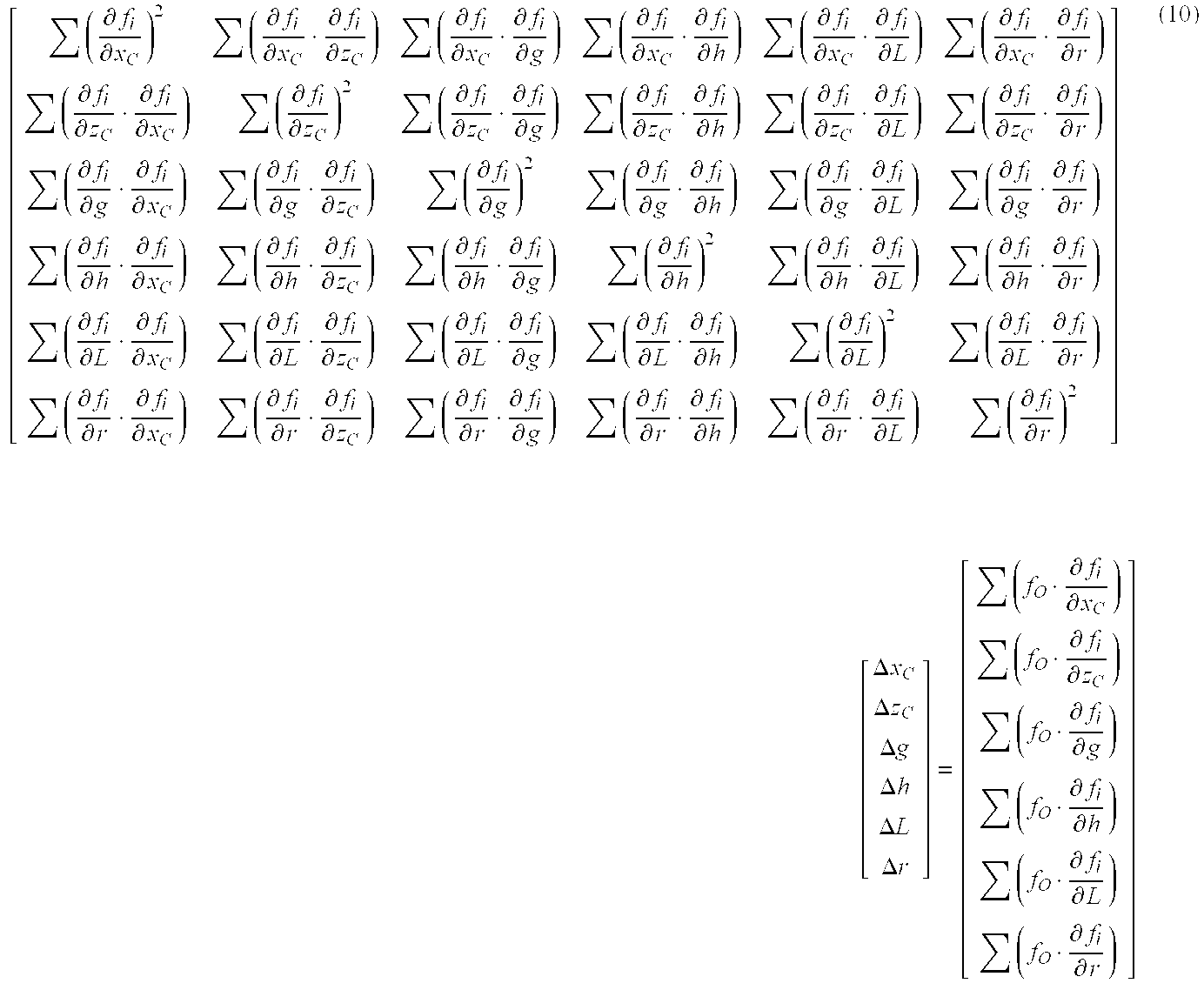
  • According to the second embodiment, the arm reference length L can be calibrated in addition to the advantages of the first embodiment. With this configuration, the present embodiment allows the calibration of the arm reference length L even when the [0087] arm 3 is replaced. The calibration of the arm reference length L further improves the measurement accuracy of the workpiece surface texture.
  • (Third Embodiment) [0088]
  • The following is the description of a third embodiment of the present invention. Although the basic configuration in the third embodiment is the same as in the first embodiment, the third embodiment is characterized in that the arm reference length L and the zeroset deviation z[0089] 0 are also subjected to the calibration in addition to those subjected to the calibration in the first embodiment.
  • In the surface [0090] texture measuring instrument 1 in the third embodiment, as shown in FIG. 4, the contact point 41 is arranged to generally match the reference point. In other words, the tip compensation amount “h” is approximately zero, and the deviation due to the swing of the arm 3 is represented by the below formula that corresponds to the formulas (5) and (6). In calculating the x-direction deviation, the zero set deviation of the second detector is counted in.
  • Herein, the zeroset deviation Z[0091] 0 is the value of the z-coordinate of the contact point 41 (the reference point P) with the base shaft of the arm 3 (the base line A) being parallel to the x-direction (or, the value derived by multiplying the detection result of the second detector 7 by the gain “g” in this condition). d x = L ( 1 - cos θ ) = L ( 1 - L 2 - ( g z - z o ) 2 L ) d z = 0 ( 11 )
    Figure US20040223148A1-20041111-M00011
  • In assigning the detection results of the [0092] first detector 6 and the second detector 7 in the evaluation formula, the value of the x-coordinate is Xi which is found by counting the deviation dx due to the swing of the swing arm 3 (see the formula (11)) in the detection result xi of the first detector 6. The value of the z-coordinate is Zi which is the z-coordinate gzi of the reference point P (the contact point 41). It is noted that the offset due to the radius of the contact point 41 and the zeroset deviation in the x-direction are disregarded. X i = x i + L ( 1 - L 2 - ( g z i - z o ) 2 L ) Z i = g z i ( 12 )
    Figure US20040223148A1-20041111-M00012
  • Then the center coordinates (x[0093] c, zc) and the radius “r” are assigned in the following evaluation formula as arbitrary variables. f i = ( X i - x c ) 2 + ( Z i - z c ) 2 - r = { x i + L ( 1 - L 2 - ( g z i - z o ) 2 L ) - x c } 2 + ( g z i - z c ) 2 - r ( 13 )
    Figure US20040223148A1-20041111-M00013
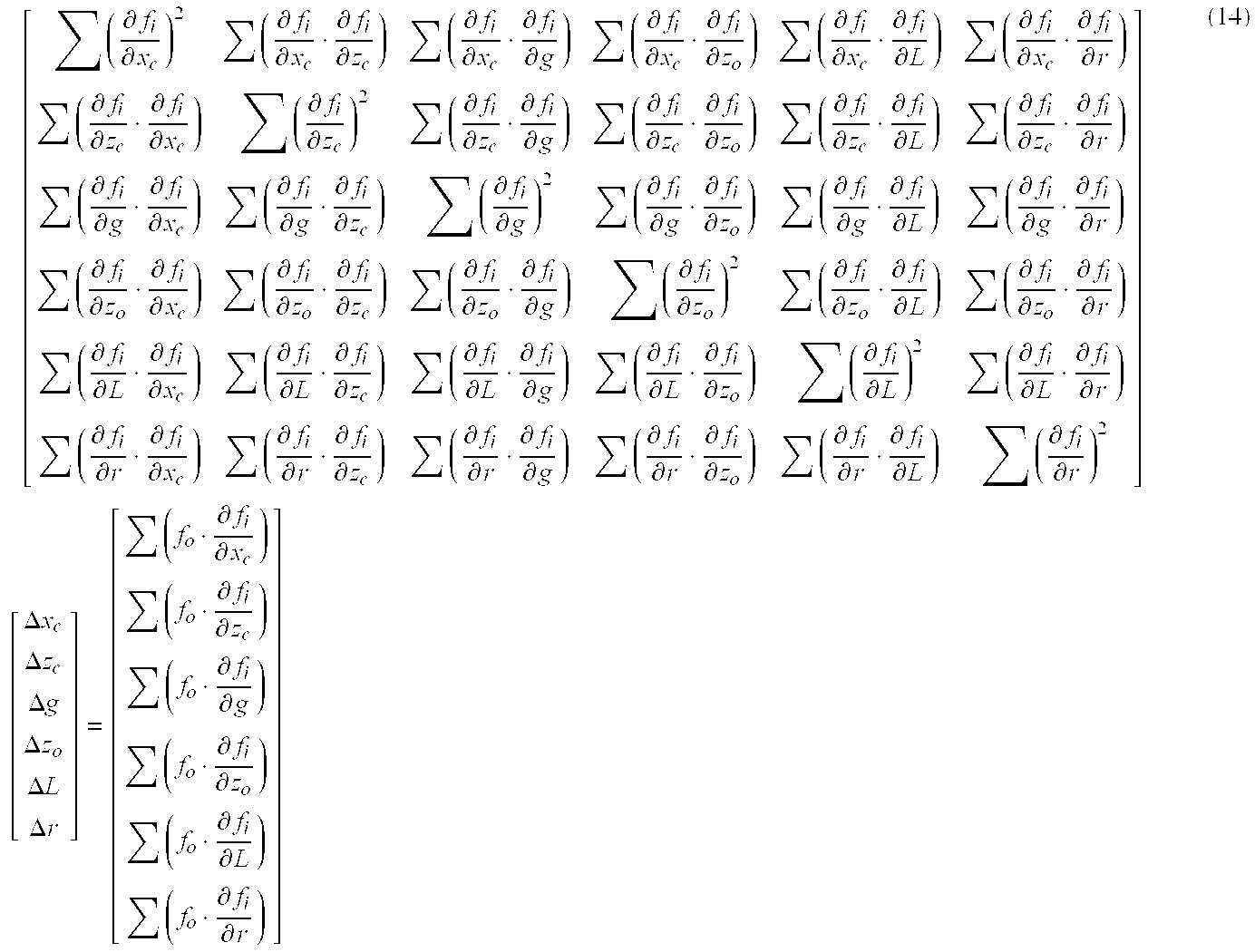
  • In applying the least square method to the evaluation formula (13) (the calibration step), the center coordinates (x[0094] c, zc), the radius “r”, the gain “g”, the zeroset deviation z0, and the arm reference length L are subjected to the calibration.
  • That is, each of the above parameters for minimizing “s” are found, where “s” is the sum of square of the evaluation formula f[0095] i. The calculation formula of the least square method is the formula below. [ ( f i x c ) 2 ( f i x c · f i z c ) ( f i x c · f i g ) ( f i x c · f i z o ) ( f i x c · f i L ) ( f i x c · f i r ) ( f i z c · f i x c ) ( f i z c ) 2 ( f i z c · f i g ) ( f i z c · f i z o ) ( f i z c · f i L ) ( f i z c · f i r ) ( f i g · f i x c ) ( f i g · f i z c ) ( f i g ) 2 ( f i g · f i z o ) ( f i g · f i L ) ( f i g · f i r ) ( f i z o · f i x c ) ( f i z o · f i z c ) ( f i z o · f i g ) ( f i z o ) 2 ( f i z o · f i L ) ( f i z o · f i r ) ( f i L · f i x c ) ( f i L · f i z c ) ( f i L · f i g ) ( f i L · f i z o ) ( f i L ) 2 ( f i L · f i r ) ( f i r · f i x c ) ( f i r · f i z c ) ( f i r · f i g ) ( f i r · f i z o ) ( f i r · f i L ) ( f i r ) 2 ] [ Δ x c Δ z c Δ g Δ z o Δ L Δ r ] = [ ( f o · f i x c ) ( f o · f i z c ) ( f o · f i g ) ( f o · f i z o ) ( f o · f i L ) ( f o · f i r ) ] ( 14 )
    Figure US20040223148A1-20041111-M00014
  • According to the third embodiment with such configuration, the zeroset deviation z[0096] 0 can be calibrated in addition to the advantages of the above embodiments. Therefore, in the arrangement where the contact point 41 generally matches the reference point P, even if the adjustment for setting the contact point 41 to match the reference point P or the adjustment for setting the detection result of the second detector to zero with the base shaft of the arm 3 (the base line A) being parallel to the x-direction, are inaccurate and hence resulted in a little adjustment error, the zeroset deviation z0 can be calibrated in the present embodiment. Consequently, the work for adjusting the position of the contact point 41 and the zero set of the second detector 7 can be simplified while accurate measurement can be performed.
  • (Fourth Embodiment) [0097]
  • The following is the description of a fourth embodiment of the present invention. Although the basic configuration in the fourth embodiment is the same as in the first embodiment, the fourth embodiment is characterized in that the arm reference length L and the zeroset deviation z[0098] 0 are also subjected to the calibration in addition to those subjected to the calibration in the first embodiment.
  • In the surface [0099] texture measuring instrument 1 in the fourth embodiment, as shown in FIG. 5, the zeroset deviation z0 is the value of the z-coordinate of the reference point P with the base shaft of the arm 3 (the base line A) being parallel to the x-direction (or, the value derived by multiplying the detection result of the second detector 7 by the gain “g” in this condition). In other words, the deviation due to the swing of the arm 3 is represented by the below formula that corresponds to the formulas (5) and (6). d x = L ( 1 - cos θ ) - h · sin θ = L ( 1 - L 2 - ( g z i - z o ) 2 L ) - h ( g z i - z o ) L d z = h ( 1 - cos θ ) = h ( 1 - L 2 - ( g z i - z o ) 2 L ) ( 15 )
    Figure US20040223148A1-20041111-M00015
  • In assigning the detection results of the [0100] first detector 6 and the second detector 7 in the evaluation formula, the x-coordinate is Xi which is found by counting the deviation dx due to the swing of the swing arm 3 (see the formula (15)) in the detection result xi of the first detector 6. The value of the z-coordinate is Zi which is found by counting the deviation dz due to the swing of the arm 3 (see the formula (15)) in the z-coordinate gzi of the reference point P. It is noted that the offset due to the radius of the contact point 41 and the tip compensation amount “h” are disregarded. X i = x i + L ( 1 - L 2 - ( g z i - z o ) 2 L ) - h ( g z i - z o ) 2 L ( 16 ) Z i = g z i + h ( 1 - L 2 - ( g z i - z o ) 2 L )
    Figure US20040223148A1-20041111-M00016
  • Then the center coordinates of the calibration gauge [0101] 10 (xc, zc) and the radius “r” are assigned in the following formula as arbitrary variables. f i = ( X i - x c ) 2 + ( Z i - z c ) 2 - r = { x i + L ( 1 - L 2 - ( g z i - z o ) 2 L ) - h ( g z i - z o ) L - x c } 2 + { g z i + h ( 1 - L 2 - ( g z i - z o ) 2 L ) - z c } 2 - r ( 17 )
    Figure US20040223148A1-20041111-M00017
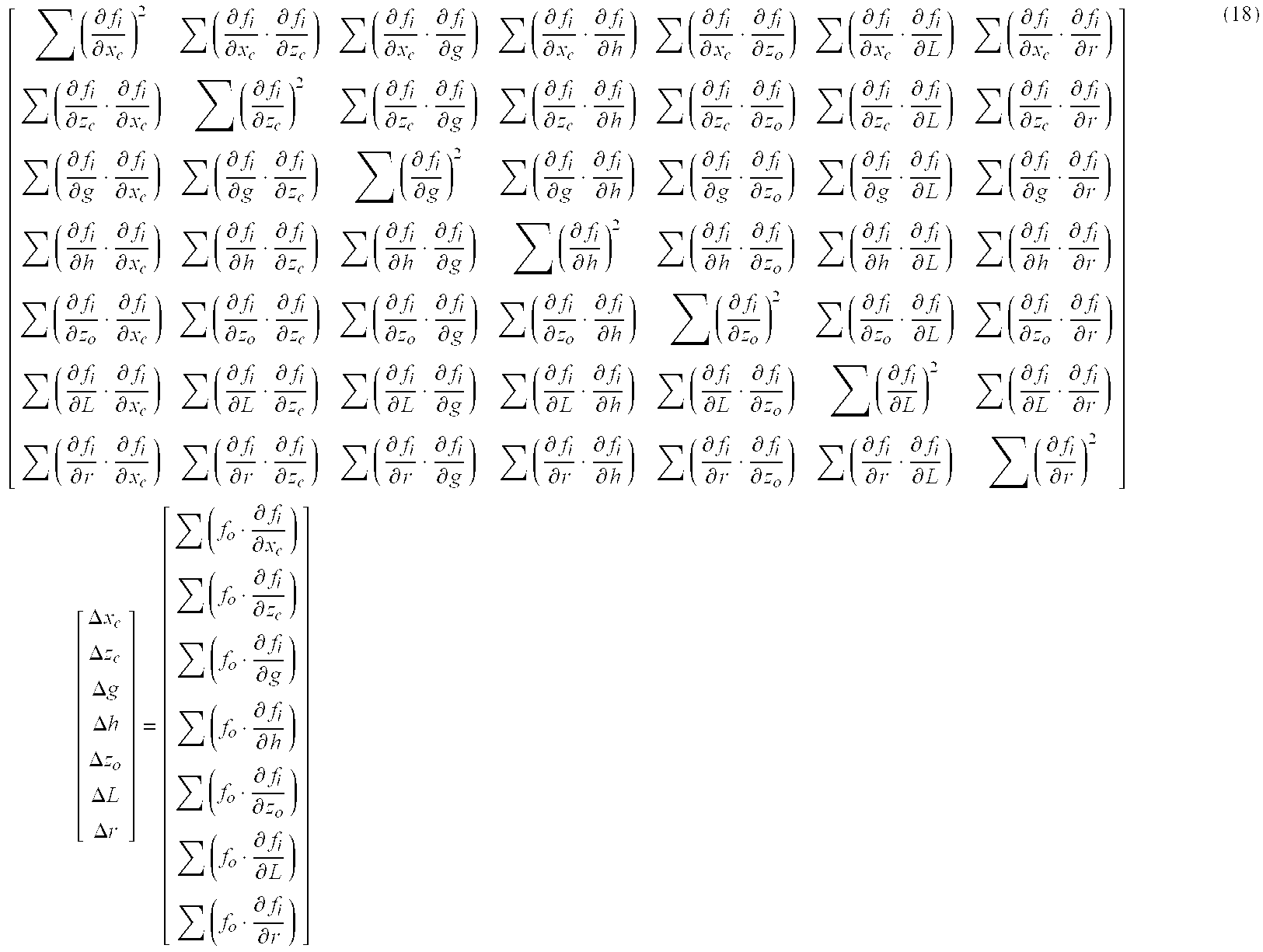
  • In applying the least square method to the evaluation formula (17) (the calibration step), the center coordinates (x[0102] c, zc), the radius “r”, the gain “g”, the zeroset deviation z0, and the arm reference length L are subjected to the calibration.
  • That is, each of the above parameters for minimizing “s” are found, where “s” is the sum of square of the evaluation formula f[0103] i. The calculation formula of the least square method is the formula below. [ ( f i x c ) 2 ( f i x c · f i z c ) ( f i x c · f i g ) ( f i x c · f i h ) ( f i x c · f i z o ) ( f i x c · f i L ) ( f i x c · f i r ) ( f i z c · f i x c ) ( f i z c ) 2 ( f i z c · f i g ) ( f i z c · f i h ) ( f i z c · f i z o ) ( f i z c · f i L ) ( f i z c · f i r ) ( f i g · f i x c ) ( f i g · f i z c ) ( f i g ) 2 ( f i g · f i h ) ( f i g · f i z o ) ( f i g · f i L ) ( f i g · f i r ) ( f i h · f i x c ) ( f i h · f i z c ) ( f i h · f i g ) ( f i h ) 2 ( f i h · f i z o ) ( f i h · f i L ) ( f i h · f i r ) ( f i z o · f i x c ) ( f i z o · f i z c ) ( f i z o · f i g ) ( f i z o · f i h ) ( f i z o ) 2 ( f i z o · f i L ) ( f i z o · f i r ) ( f i L · f i x c ) ( f i L · f i z c ) ( f i L · f i g ) ( f i L · f i h ) ( f i L · f i z o ) ( f i L ) 2 ( f i L · f i r ) ( f i r · f i x c ) ( f i r · f i z c ) ( f i r · f i g ) ( f i r · f i h ) ( f i r · f i z o ) ( f i r · f i L ) ( f i r ) 2 ] [ Δ x c Δ z c Δ g Δ h Δ z o Δ L Δ r ] = [ ( f o · f i x c ) ( f o · f i z c ) ( f o · f i g ) ( f o · f i h ) ( f o · f i z o ) ( f o · f i L ) ( f o · f i r ) ] ( 18 )
    Figure US20040223148A1-20041111-M00018
  • According to the fourth embodiment with such configuration, all the parameters necessary for the calibration can be calibrated in addition to the advantages of the above embodiments. [0104]
  • The present invention is not limited to the above-described embodiments, but includes various modifications as long as the object of the present invention can be achieved. [0105]
  • For example, the shape of the arm and the stylus is not limited to the linear shape, but may be a curved shape. Any shape may be applicable as far as the base end is swingably supported, the contact point contacts the workpiece from the direction of the tangent line of the arc, and the texture of the workpiece surface is measured based on the shift distance of the base end and the swing amount of the arm. [0106]
  • While the radius of the contact point is not subjected to the calibration in the above-described embodiments, the calibration may be performed on the radius of the contact point. That is, if the radius of the calibration gauge is known, the radius of the contact point can be found by subtracting the radius of the calibration gauge from the radius obtained with the use of the least square method. [0107]
  • While the surface texture measuring instrument is a contact type instrument of which contact point contacts and scans on the workpiece in the above description, a non-contact type contact point may be used. Even in this case, as long as the radius of the calibration gauge is known, the deviation of the contact point can be calibrated. [0108]
  • While the least square method is used as a solving method for finding each parameter based on the evaluation formula, it may be substituted by other solving methods. [0109]
  • The [0110] second detector 7 is arranged between the base point 311 (the swing center) and the reference point P in the described embodiments. Alternatively, the base shaft section 31 may be extended to the right side of the base point 311 (the swing center) and the second detector 7 may be arranged at the right side of the base point 311 (the swing center) in FIG. 1 as an example. Such configuration can be considered the same as those presented in the above embodiments except for the fact that the detection value of the second detector 7 has the sign opposite to that of the above embodiments.
  • While the gain “g” is determined based on the arm reference length L and the length Lo from the base point to the middle point in the above embodiments, the gain “g” may be calibrated as a total gain “g” in which other variations (e.g. the reference length L, the angularity of the detector, the temperature. etc) are counted. [0111]
  • While the description in the above embodiment is limited to the [0112] contact point 41 having a perfectly sphere-shaped tip and the calibration gauge having a perfectly sphere-shaped measurement surface, the shape is not limited to the perfect sphere. Specifically, a second calibration step may be provided, by giving a true shape of the calibration gauge, for calculating the tip shape of the contact point based on the difference from the radius “r” found in the calibration step. Accordingly, since the true shape of the calibration gauge is given, the tip shape of the contact point can be found based on the difference from the radius “r” found in the calibration step. Although the shape of the calibration gauge and the tip shape of the contact point are typically spherical, they are not exactly perfect spheres. Also, lengths from the nominal center of the sphere (xc, zc) to the sphere surface in each angle direction are not necessarily the same. Therefore, the lengths from the nominal center of the calibration gauge to the sphere surface in respective angle direction are measured in advance. Then the lengths in each angle direction corresponding to the detection results in the measurement step are calculated and the difference from the radius “r” found in the calibration step is found. In this way, even when the calibration gauge is not perfect sphere, accurate calibration calculation can be performed.
  • Similarly, as for the tip shape of the contact point, based on the angle corresponding to the detection result in the measurement step (measurement orientation of contact section and the like of the contact point with the calibration gauge seen from the nominal center of the contact point) and the true shape of the calibration gauge, the length from the nominal center of the contact point to the surface of the contact point at the corresponding angle (measurement orientation) can be found (The distance is found as the difference between the radius “r” at each angle found in the calibration step and the length of a corresponding section of the calibration gauge). Accordingly, if a specific area of the spherical calibration gauge is measured and the contact point is measured at each measurement orientation, the lengths at each measurement orientation can be found and therefore the tip shape of the contact point can be found. [0113]
  • Further, a computer having a CPU (Central Processing Unit) and a memory (storage unit) may be built in the surface texture measuring instrument while arranging a program so that a computer executes each step of the calibration method described in the above embodiments. With this configuration, the compensation formula and evaluation formula in each step and parameters subjected to calibration can be easily changed. The program may be stored in a recording medium and be installed in a computer by directly inserting the recording medium to the computer, or alternatively, a reader device may be externally attached to the computer to install the program in the computer through the reader device. The program may be supplied and installed to the computer wirelessly or through a communication line such as the Internet, LAN cable and telephone line. [0114]

Claims (11)

What is claimed is:
1. A calibration method for a surface texture measuring instrument that measures a surface of a workpiece, the instrument including: an arm supported to be swingable around a base point; a stylus that is arranged on an end of the arm and is provided with a contact point on a tip thereof, the contact point being in contact or nearly in contact with the workpiece along a substantial tangent line of an arc drawn by a tip of the contact point in accordance with a swing of the arm; a shifter for shifting the arm in x-direction while keeping the contact point in contact or nearly in contact with the workpiece surface; a first detector for detecting a displacement of the base point in the x-direction; a second detector for detecting a displacement in z-direction due to the swing of the arm based on a displacement of a point on the arm in the z-direction; and a compensation computing unit that compensates detection results of the first detector and the second detector for a deviation due to the swing to obtain measurement data of the workpiece surface, the calibration method comprising:
a measurement step for measuring a calibration gauge of which cross section contains a part of a substantially perfect circle;
an assignment step for assigning the detection results of the first detector and the second detector, which are obtained in the measurement step, in an evaluation formula based on a circle equation in which the center coordinates of the calibration gauge are (xc, zc) and a radius of the calibration gauge is r; and
a calibration step for calibrating gain of z-coordinate of the tip of the contact point relative to the detection result of the second detector and each parameter included in the deviation based on the results obtained in the assignment step.
2. The calibration method for the surface texture measuring instrument according to claim 1,
wherein the evaluation formula in the assignment step is determined based on: an arm reference length L as a length from the base point to a reference point as a foot of a perpendicular line extended from the tip of the contact point to a base shaft of the arm extending in longitudinal direction; a detection value xi of the first detector; a detection result zi of the second detector; a gain g of the z-coordinate of the tip of the contact point to the detection result zi of the second detector; and a tip compensation amount h as a length from the reference point to the tip of the contact point, and
wherein, with a known arm reference length L being given, the center coordinates (xc, zc), the radius r, the gain g and the tip compensation amount h are found in the calibration step.
3. The calibration method for the surface texture measuring instrument according to claim 2, wherein, based on a designed value of the arm reference length L, the center coordinates (xc, zc), the radius r, the gain g, and the tip compensation amount h are found in the calibration step.
4. The calibration method for the surface texture measuring instrument according to claim 1,
wherein the evaluation formula in the assignment step is determined based on: an arm reference length L as a length from the base point to the tip of the contact point; a detection value xi of the first detector; a detection result zi of the second detector; a gain g of the z-coordinate of the tip of the contact point to the detection result zi of the second detector; and a zeroset deviation z0 as a value derived by multiplying the detection result of the second detector, which is obtained when a line connecting the base point and the tip of the contact point tip is parallel to the x-direction, by the gain g, and
wherein the center coordinates (xc, zc) of the circle, the radius of the circle r, the gain g, the arm reference length L and the zeroset deviation z0 are found.
5. The calibration method for the surface texture measuring instrument according to claim 1,
wherein the evaluation formula in the assignment step is determined based on: an arm reference length L as a length from the base point to a reference point as a foot of a perpendicular line extended from the tip of the contact point to a base shaft of the arm extending in longitudinal direction; a detection value xi of the first detector; detection result zi of the second detector; a gain g of the z-coordinate of the tip of the contact point to the detection result zi of the second detector; a tip compensation amount h as a length from the reference point to the tip of the contact point; and a zeroset deviation z0 as a value derived by multiplying the detection result of the second detector, which is obtained when the base shaft of the arm is parallel to the x-direction, by the gain g, and
wherein the center coordinates (xc, zc) of the circle, the radius of the circle r, the tip compensation amount h, the gain g, the zeroset deviation z0 and the arm reference length L are found.
6. The calibration method for the surface texture measuring instrument according to claim 1, further comprising a second calibration step, with a true shape of the calibration gauge being given, for computing a tip shape of the contact point based on difference from the radius r found in the calibration step.
7. The calibration method for the surface texture measuring instrument according to claim 6, wherein the calibration gauge contains at least a part of a perfect circle and the true shape of the calibration gauge is represented by a radius rt of the perfect circle.
8. The calibration method for the surface texture measuring instrument according to claim 6, wherein the tip shape of the contact point contains at least a part of a perfect circle and is represented by the radius of the perfect circle.
9. A calibration program for a surface texture measuring instrument wherein a computer executes a calibration method for the surface texture measuring instrument that measures a surface of a workpiece, the instrument including: an arm supported to be swingable around a base point; a stylus that is arranged on an end of the arm and is provided with a contact point on a tip thereof, the contact point being in contact or nearly in contact with the workpiece along a substantial tangent line of an arc drawn by a tip of the contact point in accordance with a swing of the arm; a shifter for shifting the arm in x-direction while keeping the contact point in contact or nearly in contact with the workpiece surface; a first detector for detecting a displacement of the base point in the x-direction; a second detector for detecting a displacement in z-direction due to the swing of the arm based on a displacement of a point on the arm in the z-direction; and a compensation computing unit that compensates detection results of the first detector and the second detector for a deviation due to the swing to obtain measurement data of the workpiece surface, the calibration method comprising:
a measurement step for measuring a calibration gauge of which cross section contains a part of a substantially perfect circle;
an assignment step for assigning the detection results of the first detector and the second detector, which are obtained in the measurement step, in an evaluation formula based on a circle equation in which the center coordinates of the calibration gauge are (xc, zc) and a radius of the calibration gauge is r; and
a calibration step for calibrating gain of z-coordinate of the tip of the contact point relative to the detection result of the second detector and each parameter included in the deviation based on the results obtained in the assignment step.
10. A computer-readable recording medium storing a calibration program for a surface texture measuring instrument wherein a computer executes a calibration method for the surface texture measuring instrument that measures a surface of a workpiece, the instrument including: an arm supported to be swingable around a base point; a stylus that is arranged on an end of the arm and is provided with a contact point on a tip thereof, the contact point being in contact or nearly in contact with the workpiece along a substantial tangent line of an arc drawn by a tip of the contact point in accordance with a swing of the arm; a shifter for shifting the arm in x-direction while keeping the contact point in contact or nearly in contact with the workpiece surface; a first detector for detecting a displacement of the base point in the x-direction; a second detector for detecting a displacement in z-direction due to the swing of the arm based on a displacement of a point on the arm in the z-direction; and a compensation computing unit that compensates detection results of the first detector and the second detector for a deviation due to the swing to obtain measurement data of the workpiece surface, the calibration method comprising:
a measurement step for measuring a calibration gauge of which cross section contains a part of a substantially perfect circle;
an assignment step for assigning the detection results of the first detector and the second detector, which are obtained in the measurement step, in an evaluation formula based on a circle equation in which the center coordinates of the calibration gauge are (xc, zc) and a radius of the calibration gauge is r; and
a calibration step for calibrating gain of z-coordinate of the tip of the contact point relative to the detection result of the second detector and each parameter included in the deviation based on the results obtained in the assignment step.
11. A surface texture measuring instrument comprising a calibration program for the surface texture measuring instrument, the program being executable by a computer wherein the computer executes a calibration method for the surface texture measuring instrument that measures a surface of a workpiece, the instrument including: an arm supported to be swingable around a base point; a stylus that is arranged on an end of the arm and is provided with a contact point on a tip thereof, the contact point being in contact or nearly in contact with the workpiece along a substantial tangent line of an arc drawn by a tip of the contact point in accordance with a swing of the arm; a shifter for shifting the arm in x-direction while keeping the contact point in contact or nearly in contact with the workpiece surface; a first detector for detecting a displacement of the base point in the x-direction; a second detector for detecting a displacement in z-direction due to the swing of the arm based on a displacement of a point on the arm in the z-direction; and a compensation computing unit that compensates detection results of the first detector and the second detector for a deviation due to the swing to obtain measurement data of the workpiece surface, the calibration method comprising:
a measurement step for measuring a calibration gauge of which cross section contains a part of a substantially perfect circle;
an assignment step for assigning the detection results of the first detector and the second detector, which are obtained in the measurement step, in an evaluation formula based on a circle equation in which the center coordinates of the calibration gauge are (xc, zc) and a radius of the calibration gauge is r; and
a calibration step for calibrating gain of z-coordinate of the tip of the contact point relative to the detection result of the second detector and each parameter included in the deviation based on the results obtained in the assignment step.
US10/833,007 2003-05-08 2004-04-28 Calibration method for surface texture measuring instrument, calibration program for surface texture measuring instrument, recording medium storing the calibration program and surface texture measuring instrument Active 2025-04-15 US7162383B2 (en)

Applications Claiming Priority (2)

Application Number Priority Date Filing Date Title
JP2003129882A JP4323212B2 (en) 2003-05-08 2003-05-08 Calibration method for surface texture measuring instrument, calibration program for surface texture measuring instrument, recording medium recording this calibration program, and surface texture measuring instrument
JP2003-129882 2003-05-08

Publications (2)

Publication Number Publication Date
US20040223148A1 true US20040223148A1 (en) 2004-11-11
US7162383B2 US7162383B2 (en) 2007-01-09

Family

ID=32985644

Family Applications (1)

Application Number Title Priority Date Filing Date
US10/833,007 Active 2025-04-15 US7162383B2 (en) 2003-05-08 2004-04-28 Calibration method for surface texture measuring instrument, calibration program for surface texture measuring instrument, recording medium storing the calibration program and surface texture measuring instrument

Country Status (4)

Country Link
US (1) US7162383B2 (en)
EP (1) EP1475603B1 (en)
JP (1) JP4323212B2 (en)
CN (1) CN100371672C (en)

Cited By (41)

* Cited by examiner, † Cited by third party
Publication number Priority date Publication date Assignee Title
CN102168959A (en) * 2010-02-26 2011-08-31 中国海洋石油总公司 Method for detecting space position state of each circular member bar of jacket in three-dimensional coordinate system
CN102814512A (en) * 2012-08-24 2012-12-12 沈阳黎明航空发动机(集团)有限责任公司 On-line measuring method for radials profile of compressor disc-like part of engine
US20150190887A1 (en) * 2014-01-07 2015-07-09 Illinois Tool Works Inc. Calibration tool and method for a welding system
JP2015175704A (en) * 2014-03-14 2015-10-05 株式会社東京精密 Calibration method of measurement instrument and device thereof
US9352411B2 (en) 2008-05-28 2016-05-31 Illinois Tool Works Inc. Welding training system
US9368045B2 (en) 2012-11-09 2016-06-14 Illinois Tool Works Inc. System and device for welding training
US9583014B2 (en) 2012-11-09 2017-02-28 Illinois Tool Works Inc. System and device for welding training
US9583023B2 (en) 2013-03-15 2017-02-28 Illinois Tool Works Inc. Welding torch for a welding training system
US9589481B2 (en) 2014-01-07 2017-03-07 Illinois Tool Works Inc. Welding software for detection and control of devices and for analysis of data
US9666100B2 (en) 2013-03-15 2017-05-30 Illinois Tool Works Inc. Calibration devices for a welding training system
US9672757B2 (en) 2013-03-15 2017-06-06 Illinois Tool Works Inc. Multi-mode software and method for a welding training system
US9713852B2 (en) 2013-03-15 2017-07-25 Illinois Tool Works Inc. Welding training systems and devices
US9728103B2 (en) 2013-03-15 2017-08-08 Illinois Tool Works Inc. Data storage and analysis for a welding training system
US9724787B2 (en) 2014-08-07 2017-08-08 Illinois Tool Works Inc. System and method of monitoring a welding environment
US9724788B2 (en) 2014-01-07 2017-08-08 Illinois Tool Works Inc. Electrical assemblies for a welding system
US9751149B2 (en) 2014-01-07 2017-09-05 Illinois Tool Works Inc. Welding stand for a welding system
US9862049B2 (en) 2014-06-27 2018-01-09 Illinois Tool Works Inc. System and method of welding system operator identification
US9875665B2 (en) 2014-08-18 2018-01-23 Illinois Tool Works Inc. Weld training system and method
US9937578B2 (en) 2014-06-27 2018-04-10 Illinois Tool Works Inc. System and method for remote welding training
US10056010B2 (en) 2013-12-03 2018-08-21 Illinois Tool Works Inc. Systems and methods for a weld training system
US10096268B2 (en) 2011-08-10 2018-10-09 Illinois Tool Works Inc. System and device for welding training
US10105782B2 (en) 2014-01-07 2018-10-23 Illinois Tool Works Inc. Feedback from a welding torch of a welding system
US10170019B2 (en) 2014-01-07 2019-01-01 Illinois Tool Works Inc. Feedback from a welding torch of a welding system
US10204406B2 (en) 2014-11-05 2019-02-12 Illinois Tool Works Inc. System and method of controlling welding system camera exposure and marker illumination
US10210773B2 (en) 2014-11-05 2019-02-19 Illinois Tool Works Inc. System and method for welding torch display
US10239147B2 (en) 2014-10-16 2019-03-26 Illinois Tool Works Inc. Sensor-based power controls for a welding system
US10307853B2 (en) 2014-06-27 2019-06-04 Illinois Tool Works Inc. System and method for managing welding data
US10373304B2 (en) 2014-11-05 2019-08-06 Illinois Tool Works Inc. System and method of arranging welding device markers
US10373517B2 (en) 2015-08-12 2019-08-06 Illinois Tool Works Inc. Simulation stick welding electrode holder systems and methods
US10402959B2 (en) 2014-11-05 2019-09-03 Illinois Tool Works Inc. System and method of active torch marker control
US10417934B2 (en) 2014-11-05 2019-09-17 Illinois Tool Works Inc. System and method of reviewing weld data
US10427239B2 (en) 2015-04-02 2019-10-01 Illinois Tool Works Inc. Systems and methods for tracking weld training arc parameters
US10438505B2 (en) 2015-08-12 2019-10-08 Illinois Tool Works Welding training system interface
US10490098B2 (en) 2014-11-05 2019-11-26 Illinois Tool Works Inc. System and method of recording multi-run data
US10593230B2 (en) 2015-08-12 2020-03-17 Illinois Tool Works Inc. Stick welding electrode holder systems and methods
US10657839B2 (en) 2015-08-12 2020-05-19 Illinois Tool Works Inc. Stick welding electrode holders with real-time feedback features
US10665128B2 (en) 2014-06-27 2020-05-26 Illinois Tool Works Inc. System and method of monitoring welding information
US11014183B2 (en) 2014-08-07 2021-05-25 Illinois Tool Works Inc. System and method of marking a welding workpiece
US11247289B2 (en) 2014-10-16 2022-02-15 Illinois Tool Works Inc. Remote power supply parameter adjustment
US11288978B2 (en) 2019-07-22 2022-03-29 Illinois Tool Works Inc. Gas tungsten arc welding training systems
US11776423B2 (en) 2019-07-22 2023-10-03 Illinois Tool Works Inc. Connection boxes for gas tungsten arc welding training systems

Families Citing this family (16)

* Cited by examiner, † Cited by third party
Publication number Priority date Publication date Assignee Title
JP2005055282A (en) * 2003-08-04 2005-03-03 Tokyo Seimitsu Co Ltd Measuring method and measuring device
US7519502B1 (en) * 2003-09-05 2009-04-14 The United States Of America As Represented By The Secretary Of The Navy Surface profile measurement processing method
JP4694881B2 (en) * 2005-01-05 2011-06-08 株式会社ミツトヨ Uncertainty estimation method and program
GB2429291B (en) * 2005-08-18 2008-08-20 Taylor Hobson Ltd A metrological apparatus
JP4372759B2 (en) * 2006-02-10 2009-11-25 株式会社ミツトヨ Shape measuring apparatus, shape measuring method, and shape measuring program
CN101520296B (en) * 2008-12-30 2011-12-28 惠阳航空螺旋桨有限责任公司 Three-coordinate measuring method for circumferential uniformly-distributed hole true position error
JP5464943B2 (en) * 2009-08-19 2014-04-09 オリンパス株式会社 Standard piece used to evaluate the performance of measuring instruments that measure surface properties
CN101936699B (en) * 2010-08-24 2012-04-18 中国科学院光电技术研究所 Swing arm type three-dimensional contourgraph
CN103575244B (en) * 2013-11-11 2015-12-02 西安工业大学 The auto-correction method of polar coordinates probe in gear measuring system amount of bias
JP6254451B2 (en) * 2014-02-19 2017-12-27 株式会社ミツトヨ Shape measuring apparatus and method for correcting shape measuring error
JP6447997B2 (en) * 2015-02-09 2019-01-09 株式会社ミツトヨ Test indicator
DE102015209193A1 (en) 2015-05-20 2016-11-24 Carl Zeiss Industrielle Messtechnik Gmbh Method for detecting dynamic vibrations of a roughness sensor, method for measuring the roughness of a workpiece surface, computer program product and measuring device configured to carry out the method.
DE102017103938A1 (en) * 2017-02-24 2018-08-30 Carl Zeiss Industrielle Messtechnik Gmbh Device for measuring the roughness of a workpiece surface
CN106940178A (en) * 2017-03-22 2017-07-11 上海日进机床有限公司 Silicon crystal workpiece flatness detecting device and silicon crystal workpiece measurement method of planeness
JP7032994B2 (en) * 2018-05-08 2022-03-09 Dgshape株式会社 Correction device and correction method
JP7280772B2 (en) 2019-07-29 2023-05-24 株式会社ミツトヨ Parameter calibration method for surface texture measuring equipment

Citations (3)

* Cited by examiner, † Cited by third party
Publication number Priority date Publication date Assignee Title
US5669152A (en) * 1990-02-23 1997-09-23 Renishaw, Plc Touch probe
US6633051B1 (en) * 1999-04-06 2003-10-14 Renishaw Plc Surface sensing device with optical sensor
US7036238B2 (en) * 2003-12-22 2006-05-02 Mitutoyo Corporation Width-measuring method and surface texture measuring instrument

Family Cites Families (5)

* Cited by examiner, † Cited by third party
Publication number Priority date Publication date Assignee Title
DE4238139C2 (en) * 1992-11-12 2002-10-24 Zeiss Carl The coordinate
JP2727067B2 (en) 1995-06-13 1998-03-11 株式会社ミツトヨ Shape measuring instruments
JP3215325B2 (en) 1996-06-07 2001-10-02 株式会社東京精密 Measuring machine calibration method and device
JP3215354B2 (en) 1997-06-04 2001-10-02 株式会社東京精密 Measuring machine calibration method and device
JP3516630B2 (en) 2000-03-29 2004-04-05 株式会社ミツトヨ Shape measuring machine and shape measuring method

Patent Citations (3)

* Cited by examiner, † Cited by third party
Publication number Priority date Publication date Assignee Title
US5669152A (en) * 1990-02-23 1997-09-23 Renishaw, Plc Touch probe
US6633051B1 (en) * 1999-04-06 2003-10-14 Renishaw Plc Surface sensing device with optical sensor
US7036238B2 (en) * 2003-12-22 2006-05-02 Mitutoyo Corporation Width-measuring method and surface texture measuring instrument

Cited By (60)

* Cited by examiner, † Cited by third party
Publication number Priority date Publication date Assignee Title
US11749133B2 (en) 2008-05-28 2023-09-05 Illinois Tool Works Inc. Welding training system
US10748442B2 (en) 2008-05-28 2020-08-18 Illinois Tool Works Inc. Welding training system
US9352411B2 (en) 2008-05-28 2016-05-31 Illinois Tool Works Inc. Welding training system
US11423800B2 (en) 2008-05-28 2022-08-23 Illinois Tool Works Inc. Welding training system
CN102168959A (en) * 2010-02-26 2011-08-31 中国海洋石油总公司 Method for detecting space position state of each circular member bar of jacket in three-dimensional coordinate system
US10096268B2 (en) 2011-08-10 2018-10-09 Illinois Tool Works Inc. System and device for welding training
CN102814512A (en) * 2012-08-24 2012-12-12 沈阳黎明航空发动机(集团)有限责任公司 On-line measuring method for radials profile of compressor disc-like part of engine
US10417935B2 (en) 2012-11-09 2019-09-17 Illinois Tool Works Inc. System and device for welding training
US9368045B2 (en) 2012-11-09 2016-06-14 Illinois Tool Works Inc. System and device for welding training
US9583014B2 (en) 2012-11-09 2017-02-28 Illinois Tool Works Inc. System and device for welding training
US10482788B2 (en) 2013-03-15 2019-11-19 Illinois Tool Works Inc. Welding torch for a welding training system
US9713852B2 (en) 2013-03-15 2017-07-25 Illinois Tool Works Inc. Welding training systems and devices
US9728103B2 (en) 2013-03-15 2017-08-08 Illinois Tool Works Inc. Data storage and analysis for a welding training system
US9672757B2 (en) 2013-03-15 2017-06-06 Illinois Tool Works Inc. Multi-mode software and method for a welding training system
US9666100B2 (en) 2013-03-15 2017-05-30 Illinois Tool Works Inc. Calibration devices for a welding training system
US9583023B2 (en) 2013-03-15 2017-02-28 Illinois Tool Works Inc. Welding torch for a welding training system
US11127313B2 (en) 2013-12-03 2021-09-21 Illinois Tool Works Inc. Systems and methods for a weld training system
US10056010B2 (en) 2013-12-03 2018-08-21 Illinois Tool Works Inc. Systems and methods for a weld training system
US9589481B2 (en) 2014-01-07 2017-03-07 Illinois Tool Works Inc. Welding software for detection and control of devices and for analysis of data
US10964229B2 (en) 2014-01-07 2021-03-30 Illinois Tool Works Inc. Feedback from a welding torch of a welding system
US11676509B2 (en) 2014-01-07 2023-06-13 Illinois Tool Works Inc. Feedback from a welding torch of a welding system
US20150190887A1 (en) * 2014-01-07 2015-07-09 Illinois Tool Works Inc. Calibration tool and method for a welding system
US10105782B2 (en) 2014-01-07 2018-10-23 Illinois Tool Works Inc. Feedback from a welding torch of a welding system
US10170019B2 (en) 2014-01-07 2019-01-01 Illinois Tool Works Inc. Feedback from a welding torch of a welding system
US9757819B2 (en) * 2014-01-07 2017-09-12 Illinois Tool Works Inc. Calibration tool and method for a welding system
US11241754B2 (en) 2014-01-07 2022-02-08 Illinois Tool Works Inc. Feedback from a welding torch of a welding system
US9751149B2 (en) 2014-01-07 2017-09-05 Illinois Tool Works Inc. Welding stand for a welding system
US10913126B2 (en) 2014-01-07 2021-02-09 Illinois Tool Works Inc. Welding software for detection and control of devices and for analysis of data
US9724788B2 (en) 2014-01-07 2017-08-08 Illinois Tool Works Inc. Electrical assemblies for a welding system
JP2015175704A (en) * 2014-03-14 2015-10-05 株式会社東京精密 Calibration method of measurement instrument and device thereof
US10307853B2 (en) 2014-06-27 2019-06-04 Illinois Tool Works Inc. System and method for managing welding data
US9937578B2 (en) 2014-06-27 2018-04-10 Illinois Tool Works Inc. System and method for remote welding training
US10839718B2 (en) 2014-06-27 2020-11-17 Illinois Tool Works Inc. System and method of monitoring welding information
US9862049B2 (en) 2014-06-27 2018-01-09 Illinois Tool Works Inc. System and method of welding system operator identification
US10665128B2 (en) 2014-06-27 2020-05-26 Illinois Tool Works Inc. System and method of monitoring welding information
US11014183B2 (en) 2014-08-07 2021-05-25 Illinois Tool Works Inc. System and method of marking a welding workpiece
US9724787B2 (en) 2014-08-07 2017-08-08 Illinois Tool Works Inc. System and method of monitoring a welding environment
US11475785B2 (en) 2014-08-18 2022-10-18 Illinois Tool Works Inc. Weld training systems and methods
US10861345B2 (en) 2014-08-18 2020-12-08 Illinois Tool Works Inc. Weld training systems and methods
US9875665B2 (en) 2014-08-18 2018-01-23 Illinois Tool Works Inc. Weld training system and method
US10239147B2 (en) 2014-10-16 2019-03-26 Illinois Tool Works Inc. Sensor-based power controls for a welding system
US11247289B2 (en) 2014-10-16 2022-02-15 Illinois Tool Works Inc. Remote power supply parameter adjustment
US10417934B2 (en) 2014-11-05 2019-09-17 Illinois Tool Works Inc. System and method of reviewing weld data
US10402959B2 (en) 2014-11-05 2019-09-03 Illinois Tool Works Inc. System and method of active torch marker control
US10204406B2 (en) 2014-11-05 2019-02-12 Illinois Tool Works Inc. System and method of controlling welding system camera exposure and marker illumination
US10373304B2 (en) 2014-11-05 2019-08-06 Illinois Tool Works Inc. System and method of arranging welding device markers
US10210773B2 (en) 2014-11-05 2019-02-19 Illinois Tool Works Inc. System and method for welding torch display
US11127133B2 (en) 2014-11-05 2021-09-21 Illinois Tool Works Inc. System and method of active torch marker control
US11482131B2 (en) 2014-11-05 2022-10-25 Illinois Tool Works Inc. System and method of reviewing weld data
US10490098B2 (en) 2014-11-05 2019-11-26 Illinois Tool Works Inc. System and method of recording multi-run data
US10427239B2 (en) 2015-04-02 2019-10-01 Illinois Tool Works Inc. Systems and methods for tracking weld training arc parameters
US11462124B2 (en) 2015-08-12 2022-10-04 Illinois Tool Works Inc. Welding training system interface
US10657839B2 (en) 2015-08-12 2020-05-19 Illinois Tool Works Inc. Stick welding electrode holders with real-time feedback features
US11081020B2 (en) 2015-08-12 2021-08-03 Illinois Tool Works Inc. Stick welding electrode with real-time feedback features
US11594148B2 (en) 2015-08-12 2023-02-28 Illinois Tool Works Inc. Stick welding electrode holder systems and methods
US10438505B2 (en) 2015-08-12 2019-10-08 Illinois Tool Works Welding training system interface
US10593230B2 (en) 2015-08-12 2020-03-17 Illinois Tool Works Inc. Stick welding electrode holder systems and methods
US10373517B2 (en) 2015-08-12 2019-08-06 Illinois Tool Works Inc. Simulation stick welding electrode holder systems and methods
US11288978B2 (en) 2019-07-22 2022-03-29 Illinois Tool Works Inc. Gas tungsten arc welding training systems
US11776423B2 (en) 2019-07-22 2023-10-03 Illinois Tool Works Inc. Connection boxes for gas tungsten arc welding training systems

Also Published As

Publication number Publication date
CN100371672C (en) 2008-02-27
EP1475603A2 (en) 2004-11-10
JP2004333312A (en) 2004-11-25
JP4323212B2 (en) 2009-09-02
US7162383B2 (en) 2007-01-09
CN1550748A (en) 2004-12-01
EP1475603B1 (en) 2018-09-19
EP1475603A3 (en) 2011-07-06

Similar Documents

Publication Publication Date Title
US7162383B2 (en) Calibration method for surface texture measuring instrument, calibration program for surface texture measuring instrument, recording medium storing the calibration program and surface texture measuring instrument
US7131207B2 (en) Workpiece inspection method
JP3005681B1 (en) CMM calibration gauge and CMM calibration method
EP1086356B1 (en) Method of calibrating a scanning system
JP5823306B2 (en) Calibration method of surface texture measuring machine
US7376261B2 (en) Surface scan measuring device and method of forming compensation table for scanning probe
US7318284B2 (en) Method of calibrating a scanning system
US6453730B2 (en) Surface texture measuring instrument, surface texture measuring method and stylus radius measuring instrument
US5671541A (en) Accuracy verification devices for coordinate measuring machines
EP3346228B1 (en) Shape measurement device
EP0498780B1 (en) A method and arrangement for determining the linear (heat) expansion of elongated bodies
US7117110B2 (en) Measuring method and measuring apparatus
GB2288463A (en) Measuring conical threads
US7539586B2 (en) Correction method and measuring instrument
JP4098649B2 (en) Calibration tool for surface texture measuring machine, calibration method for surface texture measuring machine, calibration program for surface texture measuring machine, and recording medium recording this calibration program
US9664604B2 (en) Measurement apparatus, measurement method, and method of manufacturing article
JP7296334B2 (en) Straightness measurement system, displacement sensor calibration method, and straightness measurement method
Ouyang et al. Ball array calibration on a coordinate measuring machine using a gage block
JP6197261B2 (en) Calibration method and apparatus for measuring machine
JP4634657B2 (en) Calibration method for surface texture measuring device
JP2003232625A (en) Method of measuring straightness
TWI777205B (en) Calibration method of shape measuring device, reference device and detector
KR200182165Y1 (en) depth guage
Shen et al. A robust pretravel model for touch trigger probes in coordinate metrology

Legal Events

Date Code Title Description
AS Assignment

Owner name: MITUTOYO CORPORATION, JAPAN

Free format text: ASSIGNMENT OF ASSIGNORS INTEREST;ASSIGNOR:TAKEMURA, ISAMU;REEL/FRAME:015273/0044

Effective date: 20040415

STCF Information on status: patent grant

Free format text: PATENTED CASE

FEPP Fee payment procedure

Free format text: PAYOR NUMBER ASSIGNED (ORIGINAL EVENT CODE: ASPN); ENTITY STATUS OF PATENT OWNER: LARGE ENTITY

FPAY Fee payment

Year of fee payment: 4

FEPP Fee payment procedure

Free format text: PAYER NUMBER DE-ASSIGNED (ORIGINAL EVENT CODE: RMPN); ENTITY STATUS OF PATENT OWNER: LARGE ENTITY

Free format text: PAYOR NUMBER ASSIGNED (ORIGINAL EVENT CODE: ASPN); ENTITY STATUS OF PATENT OWNER: LARGE ENTITY

FPAY Fee payment

Year of fee payment: 8

MAFP Maintenance fee payment

Free format text: PAYMENT OF MAINTENANCE FEE, 12TH YEAR, LARGE ENTITY (ORIGINAL EVENT CODE: M1553)

Year of fee payment: 12