EP1473484A2 - Torsionsschwingungsdämpfer - Google Patents
Torsionsschwingungsdämpfer Download PDFInfo
- Publication number
- EP1473484A2 EP1473484A2 EP04009757A EP04009757A EP1473484A2 EP 1473484 A2 EP1473484 A2 EP 1473484A2 EP 04009757 A EP04009757 A EP 04009757A EP 04009757 A EP04009757 A EP 04009757A EP 1473484 A2 EP1473484 A2 EP 1473484A2
- Authority
- EP
- European Patent Office
- Prior art keywords
- area
- output
- damper
- region
- torsional vibration
- Prior art date
- Legal status (The legal status is an assumption and is not a legal conclusion. Google has not performed a legal analysis and makes no representation as to the accuracy of the status listed.)
- Granted
Links
Images

Classifications
-
- F—MECHANICAL ENGINEERING; LIGHTING; HEATING; WEAPONS; BLASTING
- F16—ENGINEERING ELEMENTS AND UNITS; GENERAL MEASURES FOR PRODUCING AND MAINTAINING EFFECTIVE FUNCTIONING OF MACHINES OR INSTALLATIONS; THERMAL INSULATION IN GENERAL
- F16F—SPRINGS; SHOCK-ABSORBERS; MEANS FOR DAMPING VIBRATION
- F16F15/00—Suppression of vibrations in systems; Means or arrangements for avoiding or reducing out-of-balance forces, e.g. due to motion
- F16F15/10—Suppression of vibrations in rotating systems by making use of members moving with the system
- F16F15/12—Suppression of vibrations in rotating systems by making use of members moving with the system using elastic members or friction-damping members, e.g. between a rotating shaft and a gyratory mass mounted thereon
- F16F15/1207—Suppression of vibrations in rotating systems by making use of members moving with the system using elastic members or friction-damping members, e.g. between a rotating shaft and a gyratory mass mounted thereon characterised by the supporting arrangement of the damper unit
-
- F—MECHANICAL ENGINEERING; LIGHTING; HEATING; WEAPONS; BLASTING
- F16—ENGINEERING ELEMENTS AND UNITS; GENERAL MEASURES FOR PRODUCING AND MAINTAINING EFFECTIVE FUNCTIONING OF MACHINES OR INSTALLATIONS; THERMAL INSULATION IN GENERAL
- F16F—SPRINGS; SHOCK-ABSORBERS; MEANS FOR DAMPING VIBRATION
- F16F15/00—Suppression of vibrations in systems; Means or arrangements for avoiding or reducing out-of-balance forces, e.g. due to motion
- F16F15/10—Suppression of vibrations in rotating systems by making use of members moving with the system
- F16F15/12—Suppression of vibrations in rotating systems by making use of members moving with the system using elastic members or friction-damping members, e.g. between a rotating shaft and a gyratory mass mounted thereon
- F16F15/121—Suppression of vibrations in rotating systems by making use of members moving with the system using elastic members or friction-damping members, e.g. between a rotating shaft and a gyratory mass mounted thereon using springs as elastic members, e.g. metallic springs
- F16F15/123—Wound springs
- F16F15/1238—Wound springs with pre-damper, i.e. additional set of springs between flange of main damper and hub
-
- F—MECHANICAL ENGINEERING; LIGHTING; HEATING; WEAPONS; BLASTING
- F16—ENGINEERING ELEMENTS AND UNITS; GENERAL MEASURES FOR PRODUCING AND MAINTAINING EFFECTIVE FUNCTIONING OF MACHINES OR INSTALLATIONS; THERMAL INSULATION IN GENERAL
- F16F—SPRINGS; SHOCK-ABSORBERS; MEANS FOR DAMPING VIBRATION
- F16F15/00—Suppression of vibrations in systems; Means or arrangements for avoiding or reducing out-of-balance forces, e.g. due to motion
- F16F15/10—Suppression of vibrations in rotating systems by making use of members moving with the system
- F16F15/12—Suppression of vibrations in rotating systems by making use of members moving with the system using elastic members or friction-damping members, e.g. between a rotating shaft and a gyratory mass mounted thereon
- F16F15/129—Suppression of vibrations in rotating systems by making use of members moving with the system using elastic members or friction-damping members, e.g. between a rotating shaft and a gyratory mass mounted thereon characterised by friction-damping means
Definitions
- the present invention relates to a torsional vibration damper, comprising a first damper area with a first input area and a first output area, which via a first damper element arrangement for torque transmission with the first input area is coupled, a second damper area with a second Input area, which with the first output area of the first damper area is in torque transmission connection, and with a second output area, via a second damper element arrangement coupled to the second input area for torque transmission is and with an output element in torque transmission connection stands, wherein a rotation angle limiting arrangement is provided which is a relative rotation between the first output range of the first damper area and the output element in a predetermined Allows angular range around an axis of rotation.
- Such a torsional vibration damper provided in a clutch disc is known from DE 39 21 283 A1.
- This two-stage constructed torsional vibration damper points as a load damper area a first damper area with the first input area carries the friction linings and with respect to its first exit area a hub acting as an output element in a predetermined Angle range is rotatable.
- a first damper area with the first input area carries the friction linings and with respect to its first exit area a hub acting as an output element in a predetermined Angle range is rotatable.
- gears each are rotatable with respect to each other with a predetermined angle of rotation and thus define a rotation angle limitation arrangement.
- the one as a pre-damper effective second damper area has an entrance area, the with the disc-shaped output area of the main damper is rotatably coupled.
- the also disc-shaped second output area of the pre-damper is with the hub, ie the Output element, for example in the area of the toothing provided there non-rotatably coupled.
- a torsional vibration damper comprising a first damper area with a first input area and a first output area, which via a first damper element arrangement for torque transmission with is coupled to the first input area, a second damper area with a second input area, that with the first output area the first damper area is in a torque transmission connection, and with a second output area, which via a second damper element arrangement for torque transmission with the second input area is coupled and with an output element in torque transmission connection stands, with a rotation angle limiting arrangement is provided which is a relative rotation between the first Output area of the first damper area and the output element in a predetermined angular range around an axis of rotation.
- the rotation angle limitation arrangement an intermediate element between the first output region of the comprises first damper region and the output element, which intermediate element with the first output area essentially non-rotatable is connected and with respect to the output element in the predetermined Angle range is rotatable.
- a first on an inner peripheral region of the intermediate element Gear formation is provided with a first counter-tooth formation on an outer peripheral region of the output element with the predetermined rotational angle range corresponding rotation movement is in mesh.
- the intermediate element be ring-shaped is.
- the intermediate element non-manufacturing restrictions of the first output area subject especially if this as a disc-like Sheet metal part is to be stamped.
- the first exit region comprises a disk element and that an extension length of the first tooth formation in the direction the axis of rotation is greater than an axial thickness of the disc element.
- the first tooth formation and the first counter-tooth formation is substantially the same Have axial extension length.
- the present invention relates to a Clutch disc, comprising a torsional vibration damper according to the invention, with the first input area of the first damper area a friction surface arrangement for torque transmission connected is and wherein the output element with an output shaft, for example Gearbox input shaft, for common rotation around the axis of rotation is connectable.
- a Clutch disc comprising a torsional vibration damper according to the invention, with the first input area of the first damper area a friction surface arrangement for torque transmission connected is and wherein the output element with an output shaft, for example Gearbox input shaft, for common rotation around the axis of rotation is connectable.
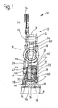
- a clutch disc is generally designated 10.
- This Clutch disc 10 includes one described in more detail below Torsional vibration damper 12 through which the friction linings 14 of this clutch disc 10 via an output hub 16 to a Transmission input shaft or the like, not shown. for common rotation can be connected with it around an axis of rotation A.
- the torsional vibration damper 12 includes two generally 18 and 20 designated damper areas.
- An output area 32 of this first damper area 18 includes a stamping technique, for example, also made of sheet metal manufactured central disc element 34. Radially outside grips this with arm sections 36 between the rivet bolts 24 with rotational movement play so that a maximum relative rotation angle for the entrance area 18 and the output area 32 is predetermined.
- damper springs 38 which in a manner known per se respective spring windows of the cover plate elements 26, 28 and the Central disk element 34 are arranged and thereon circumferentially support, the input area 18 with the output area 32 Torque transmission coupled so that due to the compressibility the damper springs 38 and the permitted relative rotatability of the Input area 18 with respect to output area 32 when Torsional vibrations a damping function can be fulfilled.
- the second damper area 20 comprises two with one another as the input area 40 and also with the central disk element 34 of the first damper area 18 non-rotatably connected and for example made of sheet metal Cover disk elements 42, 44.
- the cover disk element 44 can have a plurality of axially bent tab areas 46, which in corresponding circumferential recesses of the cover plate element 42 and Intervene openings in the central disc member 34 and thus the in Essentially rotationally fixed coupling between the input area 40 of the second damper region 20 and the output region 32 of the first Establish damper area 18.
- the output area 48 of the second damper area 20 also includes a central disc element 50, which between the two cover disc elements 42, 44 is arranged and with these over a plurality of Damper springs 52 is coupled for torque transmission.
- This too Damper springs 52 are supported on respective spring windows in the cover plate elements 42, 44 or the central disk element 50 from and thus enable a relative rotation under their circumferential compression between the input area 40 and the output area 48 of the second damper area 20.
- the output area 48 or the central disk element 50 of the second Damper area 20 is with the hub 16 in the area of one on the outer circumference the same provided toothing 54 rotatably coupled. This points also the central disk element 50 on its inner circumferential area corresponding toothing 56, which with the toothing 54 on the hub element 16 is in meshing engagement without circumferential movement play. On one the central disk element can have a stepped extension area 58 of the toothing 54 50 axially supported in one direction. This is a spring-loaded friction element 60 with respect to the cover plate element 28 of the first input area 22 on the one hand and the Central disk element 50 supported on the other hand.
- the generated by it Reactive force is via a between the other cover plate element 26 of the input area 22 and the toothing 54 of the hub 16 acting Bearing element 62 added.
- Positioning of the central disc element 50 with respect to the hub 1 6 also a defined positioning of the input area 22 of the first damper area 18 specified with respect to the hub element 16.
- a friction element 64 can be seen, which is under spring preload with respect to the cover disk element 26 on the one hand and the central disk element 34 is supported on the other hand. That way the central disk element 24 against the cover disk element 42 of the Entrance area 40 and thus the cover plate element 44 of this entrance area 40 with the interim storage of another friction or support element 66 pressed against the cover plate element 28.
- friction is also a defined positioning of the central disk element 34 in the axial direction with respect to the two cover plate elements 26, 28 and thus also given with respect to the hub 16.
- a ring-shaped Intermediate element 70 is provided between the radially inner region of the central disk element 34 of the Output area 32 and the hub 16 .
- this is with the central disk element 34 rotatably coupled, and is with the hub 16 coupled such that this intermediate element 70 in one predetermined angle of rotation range with respect to the hub 16 is rotatable. In this way it is predetermined in accordance with this Angle of rotation range also the angle of action for the second damper area 20 specified.
- intermediate element 70 The structure of the intermediate element 70 is described below with reference to FIG 2 to 4 described in detail.
- the intermediate element 70 can be seen, which has a ring-like, has essentially cylindrical body region 72.
- This body region 72 is generally 74 designated teeth provided, the six in the example shown Has teeth that mesh with the toothing 54 of the hub 16 stand that this intermediate element 70 in a predetermined Angle of rotation range with respect to the hub 16 about the axis of rotation A is rotatable.
- On the outer circumferential side of the body region 72 there is a further toothing 76 provided. With this toothing 76 is on the inner circumferential area the central disk element 34 provided teeth 78 in mesh.
- the two toothings 76, 78 are thus one on the other matched that between the intermediate element 70 and the central disc element 34 there is no rotational movement play.
- the rotation angle limiting function is thus for the second damper area 20 in the area the teeth 74, 54 is realized.
- the transmission of high torques possible because the teeth of the toothing 74 have a significantly greater axial extent can have than the teeth of the toothing 78 on the central disk element 34. So the wing load is on the individual Teeth of the toothing 74, even with a smaller number of teeth, significantly lower, so that larger torques can be transmitted.
Landscapes
- Engineering & Computer Science (AREA)
- General Engineering & Computer Science (AREA)
- Physics & Mathematics (AREA)
- Acoustics & Sound (AREA)
- Aviation & Aerospace Engineering (AREA)
- Mechanical Engineering (AREA)
- Mechanical Operated Clutches (AREA)
- Surgical Instruments (AREA)
- Buildings Adapted To Withstand Abnormal External Influences (AREA)
Abstract
Description
- Fig. 1
- eine Teil-Längsschnittansicht eines in einer Kupplungsscheibe vorgesehenen erfindungsgemäßen Torsionsschwingungsdämpfers;
- Fig. 2
- eine perspektivische Ansicht eines bei dem Torsionsschwingungsdämpfer der Fig. 1 eingesetzten ringartigen Zwischenelements;
- Fig. 3
- das Zwischenelement der Fig. 2 in Axialansicht;
- Fig. 4
- das Zwischenelement der Fig. 2 in Längsschnittansicht.
Claims (8)
- Torsionsschwingungsdämpfer, umfassend:wobei eine Drehwinkelbegrenzungsanordnung (54, 70, 74) vorgesehen ist, welche eine Relativdrehung zwischen dem ersten Ausgangsbereich (34) des ersten Dämpferbereichs (18) und dem Abtriebselement (16) in einem vorbestimmten Winkelbereich um eine Drehachse (A) zulässt,einen ersten Dämpferbereich (18) mit einem ersten Eingangsbereich (22) und einem ersten Ausgangsbereich (32), welcher über eine erste Dämpferelementenanordnung (38) zur Drehmomentübertragung mit dem ersten Eingangsbereich (22) gekoppelt ist,einen zweiten Dämpferbereich (20) mit einem zweiten Eingangsbereich (40), der mit dem ersten Ausgangsbereich (32) des ersten Dämpferbereichs (18) in Drehmomentübertragungsverbindung steht, und mit einem zweiten Ausgangsbereich (48), der über eine zweite Dämpferelementenanordnung (52) zur Drehmomentübertragung mit dem zweiten Eingangsbereich (40) gekoppelt ist und mit einem Abtriebselement (16) in Drehmomentübertragungsverbindung steht,
dadurch gekennzeichnet, dass die Drehwinkelbegrenzungsanordnung (54, 70, 74) ein Zwischenelement (70) zwischen dem ersten Ausgangsbereich (32) des ersten Dämpferbereichs (18) und dem Abtriebselement (16) umfasst, welches Zwischenelement (70) mit dem ersten Ausgangsbereich (32) im Wesentlichen drehfest verbunden ist und bezüglich des Abtriebselements (16) in dem vorbestimmten Drehwinkelbereich verdrehbar ist. - Torsionsschwingungsdämpfer nach Anspruch 1,
dadurch gekennzeichnet, dass an einem Innenumfangsbereich des Zwischenelements (70) eine erste Verzahnungsformation (74) vorgesehen ist, die mit einer ersten Gegen-Verzahnungsformation (54) an einem Außenumfangsbereich des Abtriebselements (1 6) mit dem vorbestimmten Drehwinkelbereich entsprechendem Drehbewegungsspiel in Kämmeingriff steht. - Torsionsschwingungsdämpfer nach Anspruch 1 oder 2,
dadurch gekennzeichnet, dass an einem Außenumfangsbereich des Zwischenelements (70) eine zweite Verzahnungsformation (76) vorgesehen ist, welche mit einer zweiten Gegen-Verzahnungsformation (78) am ersten Ausgangsbereich (32) des ersten Dämpferbereichs (18) im Wesentlichen ohne Drehbewegungsspiel in Kämmeingriff steht. - Torsionsschwingungsdämpfer nach einem der Ansprüche 1 bis 3,
dadurch gekennzeichnet, dass das Zwischenelement (70) ringartig ausgebildet ist. - Torsionsschwingungsdämpfer nach Anspruch 2 oder einem der Ansprüche 3 und 4, sofern auf Anspruch 2 rückbezogen,
dadurch gekennzeichnet, dass der erste Ausgangsbereich (32) ein Scheibenelement (34) umfasst und dass eine Erstreckungslänge der ersten Verzahnungsformation (74) in Richtung der Drehachse (A) größer ist, als eine axiale Dicke des Scheibenelements (34). - Torsionsschwingungsdämpfer nach Anspruch 5,
dadurch gekennzeichnet, dass die erste Verzahnungsformation (74) und die erste Gegen-Verzahnungsformation (54) im Wesentlichen die gleiche Axialerstreckungslänge aufweisen. - Torsionsschwingungsdämpfer nach einem der Ansprüche 1 bis 6,
dadurch gekennzeichnet, dass an dem Zwischenelement (70) wenigstens ein Axialanlagebereich (80) zur axialen Abstützung an dem ersten Ausgangsbereich (32) des ersten Dämpferbereichs (18) vorgesehen ist. - Kupplungsscheibe, umfassend einen Torsionsschwingungsdämpfer (12) nach einem der vorangehenden Ansprüche, wobei mit dem ersten Eingangsbereich (22) des ersten Dämpferbereichs (18) eine Reibflächenanordnung (14) zur Drehmomentübertragung verbunden ist und wobei das Abtriebselement (16) mit einer Abtriebswelle, beispielsweise Getriebeeingangswelle, zur gemeinsamen Drehung um die Drehachse (A) verbindbar ist.
Applications Claiming Priority (2)
| Application Number | Priority Date | Filing Date | Title |
|---|---|---|---|
| DE10319355 | 2003-04-30 | ||
| DE10319355A DE10319355A1 (de) | 2003-04-30 | 2003-04-30 | Torsionsschwingungsdämpfer |
Publications (3)
| Publication Number | Publication Date |
|---|---|
| EP1473484A2 true EP1473484A2 (de) | 2004-11-03 |
| EP1473484A3 EP1473484A3 (de) | 2004-11-10 |
| EP1473484B1 EP1473484B1 (de) | 2008-02-13 |
Family
ID=32981164
Family Applications (1)
| Application Number | Title | Priority Date | Filing Date |
|---|---|---|---|
| EP04009757A Expired - Lifetime EP1473484B1 (de) | 2003-04-30 | 2004-04-24 | Torsionsschwingungsdämpfer |
Country Status (3)
| Country | Link |
|---|---|
| EP (1) | EP1473484B1 (de) |
| AT (1) | ATE386224T1 (de) |
| DE (3) | DE10319355A1 (de) |
Cited By (3)
| Publication number | Priority date | Publication date | Assignee | Title |
|---|---|---|---|---|
| WO2008113316A1 (de) * | 2007-03-19 | 2008-09-25 | Luk Lamellen Und Kupplungsbau Beteiligungs Kg | Drehschwingungsdämpfer |
| CN103470686A (zh) * | 2012-06-05 | 2013-12-25 | Zf腓特烈斯哈芬股份公司 | 扭转减振器组件、特别是在离合器盘中的扭转减振器组件 |
| US20200292006A1 (en) * | 2019-03-15 | 2020-09-17 | Exedy Corporation | Damper device |
Families Citing this family (1)
| Publication number | Priority date | Publication date | Assignee | Title |
|---|---|---|---|---|
| DE102018105211A1 (de) * | 2018-03-07 | 2019-09-12 | Schaeffler Technologies AG & Co. KG | Kupplungsscheibennabe, Bausatz aus Kupplungsscheibennabe und Drehschwingungsdämpfer, Verfahren zum Herstellen einer Kupplungsscheibennabe |
Family Cites Families (7)
| Publication number | Priority date | Publication date | Assignee | Title |
|---|---|---|---|---|
| DE3542491C2 (de) * | 1985-11-30 | 1996-03-21 | Fichtel & Sachs Ag | Kupplungsscheibe für eine Kraftfahrzeug-Reibungskupplung |
| FR2624939B1 (fr) * | 1987-12-16 | 1990-04-27 | Valeo | Dispositif amortisseur de torsion |
| DE3921283A1 (de) * | 1989-02-08 | 1990-08-09 | Fichtel & Sachs Ag | Kupplungsscheibe mit torsionsschwingungsdaempfer und radial elastischer lagerung |
| FR2689191B1 (fr) * | 1992-03-26 | 1998-04-10 | Valeo | Friction d'embrayage, notamment pour vehicule industriel. |
| DE4314856A1 (de) * | 1992-05-14 | 1993-11-18 | Valeo | Schwingungsdämpfer für eine Lamellenkupplung |
| FR2725256B1 (fr) * | 1994-09-29 | 1996-11-29 | Valeo | Dispositif preamortisseur de torsion |
| FR2736111B1 (fr) * | 1995-06-29 | 1997-09-05 | Valeo | Dispositif amortisseur de torsion |
-
2003
- 2003-04-30 DE DE10319355A patent/DE10319355A1/de not_active Withdrawn
-
2004
- 2004-04-23 DE DE200410019797 patent/DE102004019797A1/de not_active Withdrawn
- 2004-04-24 EP EP04009757A patent/EP1473484B1/de not_active Expired - Lifetime
- 2004-04-24 DE DE502004006157T patent/DE502004006157D1/de not_active Expired - Lifetime
- 2004-04-24 AT AT04009757T patent/ATE386224T1/de not_active IP Right Cessation
Cited By (5)
| Publication number | Priority date | Publication date | Assignee | Title |
|---|---|---|---|---|
| WO2008113316A1 (de) * | 2007-03-19 | 2008-09-25 | Luk Lamellen Und Kupplungsbau Beteiligungs Kg | Drehschwingungsdämpfer |
| CN103470686A (zh) * | 2012-06-05 | 2013-12-25 | Zf腓特烈斯哈芬股份公司 | 扭转减振器组件、特别是在离合器盘中的扭转减振器组件 |
| CN103470686B (zh) * | 2012-06-05 | 2016-12-28 | Zf腓特烈斯哈芬股份公司 | 扭转减振器组件、特别是在离合器盘中的扭转减振器组件 |
| US20200292006A1 (en) * | 2019-03-15 | 2020-09-17 | Exedy Corporation | Damper device |
| US11619282B2 (en) * | 2019-03-15 | 2023-04-04 | Exedy Corporation | Damper device |
Also Published As
| Publication number | Publication date |
|---|---|
| DE502004006157D1 (de) | 2008-03-27 |
| ATE386224T1 (de) | 2008-03-15 |
| DE102004019797A1 (de) | 2004-11-18 |
| EP1473484B1 (de) | 2008-02-13 |
| EP1473484A3 (de) | 2004-11-10 |
| DE10319355A1 (de) | 2004-11-18 |
Similar Documents
| Publication | Publication Date | Title |
|---|---|---|
| DE3415926C2 (de) | ||
| DE19802251B4 (de) | Schlingfederkupplung | |
| EP2340378B1 (de) | Torsionsschwingungsdämpferanordnung, insbesondere für den antriebsstrang eines fahrzeugs | |
| DE3345409A1 (de) | Torsions-schwingungsdaempfer mit integriertem vordaempfer | |
| DE19912968A1 (de) | Torsionsschwingungsdämpfer | |
| DE4026765C2 (de) | Kupplungsscheibe mit Reibungsdämpfung im Leerlaufbereich | |
| EP2097657A1 (de) | Torsionsschwingungsdämpfer mit mehrteiligem primärelement | |
| DE3227004A1 (de) | Kupplungsscheibe mit reibungsdaempfer und blattfedern | |
| EP2347145B1 (de) | Torsionsschwingungsdämpfer für den antriebsstrang eines fahrzeugs | |
| EP1462675A2 (de) | Drehschwingungsdämpfer | |
| DE102008000822B4 (de) | Einrichtung zur Reduzierung von Rasselgeräuschen in Stufengetrieben | |
| EP1473484A2 (de) | Torsionsschwingungsdämpfer | |
| DE102004016365B4 (de) | Drehmomentübertragungsvorrichtung | |
| DE10227971A1 (de) | Nabenring, Abdeckblech und Kupplungsscheibe | |
| EP1626196B1 (de) | Torsionsschwingungsdämpfer, insbesondere für eine Kupplungsscheibe | |
| DE10231513A1 (de) | Mehrfach-Kupplungsanordnung | |
| DE19950597A1 (de) | Antriebsanordnung | |
| DE102015121705A1 (de) | Kupplungsanordnung, insbesondere zum optionalen Verbinden eines Luftverdichters mit einer Antriebseinrichtung | |
| DE102004012086A1 (de) | Torsionsschwingungsdämpfer | |
| DE10227265A1 (de) | Kupplungsscheibenanordnung für eine Mehrscheibenkupplung | |
| EP1496289A1 (de) | Torsionsschwingungsdämpfer sowie Reibklotz für einen Torsionsschwingungsdämpfer | |
| DE3501466C2 (de) | Torsionsschwingungsdämpfer mit im Verdrehwinkelbereich des Leerlaufsystems wirksamer, drehzahlabhängiger Reibeinrichtung | |
| DE19949362A1 (de) | Torsionsschwingungsdämpfer | |
| EP1979647B1 (de) | Torsionsschwingungsdämpfer | |
| DE102017129974A1 (de) | Drehmomentübertragungsvorrichtung mit einem mit Anschlägen ausgestatteten Phasenorgan |
Legal Events
| Date | Code | Title | Description |
|---|---|---|---|
| PUAI | Public reference made under article 153(3) epc to a published international application that has entered the european phase |
Free format text: ORIGINAL CODE: 0009012 |
|
| PUAL | Search report despatched |
Free format text: ORIGINAL CODE: 0009013 |
|
| AK | Designated contracting states |
Kind code of ref document: A2 Designated state(s): AT BE BG CH CY CZ DE DK EE ES FI FR GB GR HU IE IT LI LU MC NL PL PT RO SE SI SK TR |
|
| AX | Request for extension of the european patent |
Extension state: AL HR LT LV MK |
|
| AK | Designated contracting states |
Kind code of ref document: A3 Designated state(s): AT BE BG CH CY CZ DE DK EE ES FI FR GB GR HU IE IT LI LU MC NL PL PT RO SE SI SK TR |
|
| AX | Request for extension of the european patent |
Extension state: AL HR LT LV MK |
|
| RIC1 | Information provided on ipc code assigned before grant |
Ipc: 7F 16F 15/123 B Ipc: 7F 16F 15/12 A |
|
| 17P | Request for examination filed |
Effective date: 20041016 |
|
| 17Q | First examination report despatched |
Effective date: 20041213 |
|
| AKX | Designation fees paid |
Designated state(s): AT BE BG CH CY CZ DE DK EE ES FI FR GB GR HU IE IT LI LU MC NL PL PT RO SE SI SK TR |
|
| GRAP | Despatch of communication of intention to grant a patent |
Free format text: ORIGINAL CODE: EPIDOSNIGR1 |
|
| GRAS | Grant fee paid |
Free format text: ORIGINAL CODE: EPIDOSNIGR3 |
|
| GRAA | (expected) grant |
Free format text: ORIGINAL CODE: 0009210 |
|
| AK | Designated contracting states |
Kind code of ref document: B1 Designated state(s): AT BE BG CH CY CZ DE DK EE ES FI FR GB GR HU IE IT LI LU MC NL PL PT RO SE SI SK TR |
|
| REG | Reference to a national code |
Ref country code: GB Ref legal event code: FG4D Free format text: NOT ENGLISH |
|
| REG | Reference to a national code |
Ref country code: CH Ref legal event code: EP |
|
| REG | Reference to a national code |
Ref country code: IE Ref legal event code: FG4D Free format text: LANGUAGE OF EP DOCUMENT: GERMAN |
|
| REF | Corresponds to: |
Ref document number: 502004006157 Country of ref document: DE Date of ref document: 20080327 Kind code of ref document: P |
|
| PG25 | Lapsed in a contracting state [announced via postgrant information from national office to epo] |
Ref country code: ES Free format text: LAPSE BECAUSE OF FAILURE TO SUBMIT A TRANSLATION OF THE DESCRIPTION OR TO PAY THE FEE WITHIN THE PRESCRIBED TIME-LIMIT Effective date: 20080524 Ref country code: FI Free format text: LAPSE BECAUSE OF FAILURE TO SUBMIT A TRANSLATION OF THE DESCRIPTION OR TO PAY THE FEE WITHIN THE PRESCRIBED TIME-LIMIT Effective date: 20080213 |
|
| NLV1 | Nl: lapsed or annulled due to failure to fulfill the requirements of art. 29p and 29m of the patents act | ||
| REG | Reference to a national code |
Ref country code: HU Ref legal event code: AG4A Ref document number: E003233 Country of ref document: HU |
|
| PG25 | Lapsed in a contracting state [announced via postgrant information from national office to epo] |
Ref country code: PL Free format text: LAPSE BECAUSE OF FAILURE TO SUBMIT A TRANSLATION OF THE DESCRIPTION OR TO PAY THE FEE WITHIN THE PRESCRIBED TIME-LIMIT Effective date: 20080213 Ref country code: SI Free format text: LAPSE BECAUSE OF FAILURE TO SUBMIT A TRANSLATION OF THE DESCRIPTION OR TO PAY THE FEE WITHIN THE PRESCRIBED TIME-LIMIT Effective date: 20080213 |
|
| REG | Reference to a national code |
Ref country code: IE Ref legal event code: FD4D |
|
| BERE | Be: lapsed |
Owner name: ZF SACHS A.G. Effective date: 20080430 |
|
| PG25 | Lapsed in a contracting state [announced via postgrant information from national office to epo] |
Ref country code: SK Free format text: LAPSE BECAUSE OF FAILURE TO SUBMIT A TRANSLATION OF THE DESCRIPTION OR TO PAY THE FEE WITHIN THE PRESCRIBED TIME-LIMIT Effective date: 20080213 Ref country code: SE Free format text: LAPSE BECAUSE OF FAILURE TO SUBMIT A TRANSLATION OF THE DESCRIPTION OR TO PAY THE FEE WITHIN THE PRESCRIBED TIME-LIMIT Effective date: 20080513 Ref country code: CZ Free format text: LAPSE BECAUSE OF FAILURE TO SUBMIT A TRANSLATION OF THE DESCRIPTION OR TO PAY THE FEE WITHIN THE PRESCRIBED TIME-LIMIT Effective date: 20080213 Ref country code: DK Free format text: LAPSE BECAUSE OF FAILURE TO SUBMIT A TRANSLATION OF THE DESCRIPTION OR TO PAY THE FEE WITHIN THE PRESCRIBED TIME-LIMIT Effective date: 20080213 Ref country code: NL Free format text: LAPSE BECAUSE OF FAILURE TO SUBMIT A TRANSLATION OF THE DESCRIPTION OR TO PAY THE FEE WITHIN THE PRESCRIBED TIME-LIMIT Effective date: 20080213 Ref country code: IE Free format text: LAPSE BECAUSE OF FAILURE TO SUBMIT A TRANSLATION OF THE DESCRIPTION OR TO PAY THE FEE WITHIN THE PRESCRIBED TIME-LIMIT Effective date: 20080213 Ref country code: PT Free format text: LAPSE BECAUSE OF FAILURE TO SUBMIT A TRANSLATION OF THE DESCRIPTION OR TO PAY THE FEE WITHIN THE PRESCRIBED TIME-LIMIT Effective date: 20080714 |
|
| PG25 | Lapsed in a contracting state [announced via postgrant information from national office to epo] |
Ref country code: RO Free format text: LAPSE BECAUSE OF FAILURE TO SUBMIT A TRANSLATION OF THE DESCRIPTION OR TO PAY THE FEE WITHIN THE PRESCRIBED TIME-LIMIT Effective date: 20080213 Ref country code: MC Free format text: LAPSE BECAUSE OF NON-PAYMENT OF DUE FEES Effective date: 20080430 |
|
| REG | Reference to a national code |
Ref country code: CH Ref legal event code: PL |
|
| PLBE | No opposition filed within time limit |
Free format text: ORIGINAL CODE: 0009261 |
|
| STAA | Information on the status of an ep patent application or granted ep patent |
Free format text: STATUS: NO OPPOSITION FILED WITHIN TIME LIMIT |
|
| 26N | No opposition filed |
Effective date: 20081114 |
|
| GBPC | Gb: european patent ceased through non-payment of renewal fee |
Effective date: 20080513 |
|
| PG25 | Lapsed in a contracting state [announced via postgrant information from national office to epo] |
Ref country code: CH Free format text: LAPSE BECAUSE OF NON-PAYMENT OF DUE FEES Effective date: 20080430 Ref country code: EE Free format text: LAPSE BECAUSE OF FAILURE TO SUBMIT A TRANSLATION OF THE DESCRIPTION OR TO PAY THE FEE WITHIN THE PRESCRIBED TIME-LIMIT Effective date: 20080213 Ref country code: LI Free format text: LAPSE BECAUSE OF NON-PAYMENT OF DUE FEES Effective date: 20080430 |
|
| PG25 | Lapsed in a contracting state [announced via postgrant information from national office to epo] |
Ref country code: BE Free format text: LAPSE BECAUSE OF NON-PAYMENT OF DUE FEES Effective date: 20080430 |
|
| PG25 | Lapsed in a contracting state [announced via postgrant information from national office to epo] |
Ref country code: BG Free format text: LAPSE BECAUSE OF FAILURE TO SUBMIT A TRANSLATION OF THE DESCRIPTION OR TO PAY THE FEE WITHIN THE PRESCRIBED TIME-LIMIT Effective date: 20080513 |
|
| PG25 | Lapsed in a contracting state [announced via postgrant information from national office to epo] |
Ref country code: GB Free format text: LAPSE BECAUSE OF NON-PAYMENT OF DUE FEES Effective date: 20080513 |
|
| PG25 | Lapsed in a contracting state [announced via postgrant information from national office to epo] |
Ref country code: CY Free format text: LAPSE BECAUSE OF FAILURE TO SUBMIT A TRANSLATION OF THE DESCRIPTION OR TO PAY THE FEE WITHIN THE PRESCRIBED TIME-LIMIT Effective date: 20080213 |
|
| PG25 | Lapsed in a contracting state [announced via postgrant information from national office to epo] |
Ref country code: IT Free format text: LAPSE BECAUSE OF FAILURE TO SUBMIT A TRANSLATION OF THE DESCRIPTION OR TO PAY THE FEE WITHIN THE PRESCRIBED TIME-LIMIT Effective date: 20080213 Ref country code: AT Free format text: LAPSE BECAUSE OF NON-PAYMENT OF DUE FEES Effective date: 20080424 |
|
| PGFP | Annual fee paid to national office [announced via postgrant information from national office to epo] |
Ref country code: HU Payment date: 20090415 Year of fee payment: 6 |
|
| PG25 | Lapsed in a contracting state [announced via postgrant information from national office to epo] |
Ref country code: LU Free format text: LAPSE BECAUSE OF NON-PAYMENT OF DUE FEES Effective date: 20080424 |
|
| PG25 | Lapsed in a contracting state [announced via postgrant information from national office to epo] |
Ref country code: TR Free format text: LAPSE BECAUSE OF FAILURE TO SUBMIT A TRANSLATION OF THE DESCRIPTION OR TO PAY THE FEE WITHIN THE PRESCRIBED TIME-LIMIT Effective date: 20080213 |
|
| PG25 | Lapsed in a contracting state [announced via postgrant information from national office to epo] |
Ref country code: GR Free format text: LAPSE BECAUSE OF FAILURE TO SUBMIT A TRANSLATION OF THE DESCRIPTION OR TO PAY THE FEE WITHIN THE PRESCRIBED TIME-LIMIT Effective date: 20080514 |
|
| PG25 | Lapsed in a contracting state [announced via postgrant information from national office to epo] |
Ref country code: HU Free format text: LAPSE BECAUSE OF NON-PAYMENT OF DUE FEES Effective date: 20100425 |
|
| PGFP | Annual fee paid to national office [announced via postgrant information from national office to epo] |
Ref country code: FR Payment date: 20120504 Year of fee payment: 9 |
|
| REG | Reference to a national code |
Ref country code: DE Ref legal event code: R081 Ref document number: 502004006157 Country of ref document: DE Owner name: ZF FRIEDRICHSHAFEN AG, DE Free format text: FORMER OWNER: ZF SACHS AG, 97424 SCHWEINFURT, DE Effective date: 20130326 |
|
| PGFP | Annual fee paid to national office [announced via postgrant information from national office to epo] |
Ref country code: DE Payment date: 20130508 Year of fee payment: 10 |
|
| REG | Reference to a national code |
Ref country code: FR Ref legal event code: ST Effective date: 20131231 |
|
| PG25 | Lapsed in a contracting state [announced via postgrant information from national office to epo] |
Ref country code: FR Free format text: LAPSE BECAUSE OF NON-PAYMENT OF DUE FEES Effective date: 20130430 |
|
| REG | Reference to a national code |
Ref country code: DE Ref legal event code: R119 Ref document number: 502004006157 Country of ref document: DE |
|
| REG | Reference to a national code |
Ref country code: DE Ref legal event code: R119 Ref document number: 502004006157 Country of ref document: DE Effective date: 20141101 |
|
| PG25 | Lapsed in a contracting state [announced via postgrant information from national office to epo] |
Ref country code: DE Free format text: LAPSE BECAUSE OF NON-PAYMENT OF DUE FEES Effective date: 20141101 |